Note : Les descriptions sont présentées dans la langue officielle dans laquelle elles ont été soumises.
~`l D-20087 213193~ -
, ~ , .
- 1 . ;
FLUE SYSTEM COMBUSTION
. . .
Technical Field
The invention relates generally to furnace ;
combustion wherein heat is produced to heat a charge. ~`
Background Art
Many industrial processes employ furnaces wherein
fuel and oxidant are combusted to generate heat which
is used to heat a charge within the furnace. Among
such industrial processes one can name glassmaking
wherein the charge is glassmaking materials or molten
or solid glass, steelmaking wherein the charge is steel
or iron and all~m;nllm melting wherein the charge is
alllm;nllm ingots or scrap.
In carrying out such furnace combustion it is
desirable to completely combust the fuel within the
furnace as this serves to maximize the amount of heat ~;
released within the furnace and available to heat the ~ ~
charge. Accordingly, oxidant and fuel may be provided ~ `"
into the furnace in a ratio which is not
substoichiometric since a substoichiometric ratio would
cause some of the fuel to remain unburned or would -`
result in the generation of significant amounts of
products of incomplete combustion such as carbon
m~nox; de, hydrocarbons and carbon. !.
At first glance it would appear that the optimum
ratio for providing oxidant and fuel into a furnace for
combustion is one that is substantially stoichiometric.
However, in practice, such firing leads to some
incomplete combustion because of less than perfect
mixing of fuel and oxidant within the furnace and also
because the reaction kinetic~ of the fuel and oxidant
may ~ot enable all of the fuel to completely combust
- .
1- D-20087
~. ` , 213:~g3~
. . ~
. 2 . .
. .
prior to exiting the furnace. Accordingly, in actual
industrial practice, furnaces of this type are operated
with excess oxygen to ensure the complete combustion of ~-
the fuel within the furnace. Unfortunately, when
; ~ furnaces are operated in this way, i.e., where oxidant
and fuel are provided into the furnace in a
superstoichiometric ratio, there arises the tendency to
generate excessive levels of nitrogen oxides (NO~
because oxygen in excess of that needed to react with ;;
the fuel becomes available to combine with nitrogen to
form NO~. NO~is a significant pollutant and there
exists a need to reduce the amount of NO~ generated
- when carrying out combustion. -
Accordingly, it is an object of this in~ention to
provide a method for carrying out essentially complete
combustion to generate heat efficiently within a
furnace to heat a charge while avoiding the generation ~
` of high levels of N0~. ;;
Summary of the Invention -
The above and other objects which will become ~ ~
apparent to one skilled in the art upon a reading of ;;
this disclosure are att~'ne~ by the present invention -
which is~
A method for carrying out combustion comprising:
(A) providing fuel and oxidant in a
s~bstantially stoichiometric ratio into a furnace which
! iS in flow comml~nlcation with a flue system and which ``
contains a charge;
(B) combusting said fuel and oxidant within
the furnace to produce combustion reaction gases
including carbon monoxide, and to generate heat for i~
heating the charge;
'' '` :'`'.'
' .~
D-20087
2~ 31~38
3 i
.
(C) passiny combustion reaction gases from ! ,~.,
the furnace into the flue system;
(D) injecting secondary oxidant at a
velocity of at least 20 feet per second into the flue
system at a location where the temperature of the
combustion reaction gases is at least 1600F; and
(E) reacting secondary oxidant with carbon
m~nox;de contained in the combustion reaction gases
within the flue system to produce carbon dioxide.
As used herein, the term "substantially
stoichiometric" means not less than 99 percent or more
than 105 percent of stoichiometric.
As used herein, the term "flue system" means a `~
passage commlln;cating with a furnace by a conduit
having a narrower cross-sectional flow area than does
the furnace, said passage capable of passing furnace ~ -
gases from the furnace to the ambient atmosphere.
As used herein the term ~ambient atmospherel' means
the outside atmosphere or an inside atmosphere which
can pass or leak into the outside atmosphere.
As used herein, the term "charge" means material
within a furnace which is intended to be heated and in
some cases melted. ~-
: .
Brief Description of the Drawing
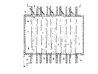
The sole Figure is a simplified plan view
representation of one emhodiment of the invention as it
, may be practiced in conjunction with a cross-fired~;
furnace. i
;
Detailed Description
The invention will be described in detail with `
reference to the drawing.
:~ '
,:
' ` ~ ,~ ` d ~ ~
; D-20087
--- 2~ZZ 3~ ~38
- 4 -
Referring now to the Figure there is illustrated a
plan view of cross-fired glassmelting furnac~ 10. The
practice of this invention will have particular utility
in regenerative glassmelting furnaces where physical
obstructions make introducing rZecondary o~idant into
the combustion chamber difficu:lt. Other types of
furnaces wherein the invention may be advantageously
practiced include steel reheating furnaces and aluminum ^;~
melting furnaces. Furnace 10 contains a charge 2 of ~ -
glassmaking materials and molten glass which pass
through the furnace underneath the cross-fired flames.
Fuel and furnace oxidant are provided into the
furnace in a substantially stoichiometric ratio through
one or more burners or ports 11. In the embodiment-~
illustrated in the Figure, five such burners are shown.
The fuel may be any fluid fuel such as methane,
propane, natural gas or fuel oil. The oxidant may be ;~
air or a fluid having an oxygen concentration greater
than that of air.
Within furnace 10 the fuel and oxidant combust
such as is illustrated by ~lames 1 in the Figure. The
combustion generates heat which i5 employed within the
furnace to heat, and in some cases to melt, the charge. -~
In carrying out the combustion there are produced
combustion reaction gases. The temperature of the
combustion reaction gases produced in the furnace is
generally within the range of from 2200 to 3100F.
~ecause of the substantially stoichiometric ratio at
which the fuel and oxidant are provided into the ~ -
furnace, most of the combustion reaction gases produced
are products of complete combustion, i.e., carbon
dioxide and water vapor. However, there are also
produced some products of incomplete combustion
, '
, '' ':
~ D-20087
2,~,3193~
- 5 -
including carbon monoxide and perhaps hydrocarbons and
carbon in the combustion reaction gases.
The combustion reaction ga~es are passed from the
furnace into the flue system. In the embodiment
i 5 illustrated in the Figure the flue system comprises
chimney system 5, which can pass the gases into the
ambient atmosphere, and exhaust port 3 which
commllnlcates with the furnace. The cross-sectional
flow area 12 where the flue system communicates with
the furnace is smaller than the cross-sectional flow
area of the furnace through which the combusting fuel
and oxidant travel. The e~bodiment illustrated in the
Figure illustrates five exhaust ports each
corresponding to a burner. It will be recognized by
1~ one skilled in the art that the invention may be
practiced with any practical number of burners and
exhaust ports including one burner and/or one exhaust
port.
Secondary oxidant is injected into the flue
system, preferably, as illustrated in the Figure, into ~;
the exhaust port or ports. The secondary oxidant is
injected into the flue system through lance 4. As
mentioned, the Figure is a simplified representation
intended to illustrate the method of thi~ invention.
Accordingly, there is not shown the sources of fuel and
oxidant. Those skilled in ~he art will readily
recognize the fuel and oxidant are provided to the
, burners and lances from appropriate sources through
conduits which are not shown. The secondary oxidant
rnay be air or a fluid having an oxygen concentration
greater than that of air. Preferably the eecondary
oxidant has an oxygen concentration of at least 80 mole
percent and rnost preferably greater than 90 mole
percent.
~ .
: :;'.-
:
D-20087 2~3193~
. .
......
.
- A high oxygen concentration in the secondary
oxidant is preferred because this enables a smaller
volume of secondary oxidant to oxidize a given quantity
of products of incomplete combustion. Therefore the
pressure of the secondary oxidant and/or the size ~f
conduits and lances for secondary oxidant can be ~;
reduced. The volume of gas to be passed through the ; -
flue system is also reduced, which can be advantageous
if the flue system area is restricted due to fac~ors
such as clogging by particulates, as often happens in
glassmelting facilities. High secondary oxidant oxygen
- conc~ntration is also preferable if a system is in
place to capture useful heat from the furnace exhaust
i gases, as in the case of regenerative glass meltling ~;
furnaces. Since less diluent, which is mostly
nitrogen, is present in the secondary oxidant, furnace
fuel efficiency is impacted less by heat being absorbed
and carried away by the diluent gases.
The concentration of products of incomplete
20 combustion within the combustion reaction gases passing
through the flue system is relatively low because the
oxidant and fuel are provided into the furnace in a
substantially stoichiometric ratio and not at a
significantly substoichiometric ratio. In order for
2~ the secondary oxidant to effectively burn out the `
products of incomplete combustion, some residence time ~ ~
at a high temperature is required. This is achieved by - ~-
injecting the secondary oxidant into the flue system at
a location where the com~ustion reaction gases are at a
temperature of at least 1600F. Below 1600 F the
reaction kinetics of the oxidation of carbon mnnox;de
proceed too ~;lowly for the effective utilization of the
method of this invention. Preferably the temperature ;~
'' '',~,''~
' ';
- D-20087 21 ~
~,
- 7
of the combustion reaction gases at the s~condary
oxidant injection location will be at least 2000F.
The secondary oxidant injection must create
sufficient turbulence or flow disruption to mix with
and combust the relatively dilute products of
incomplete combustion which may include hydrocarbons in
addition to carbon monoxide. Such desired flow effects
are attained by injecting the secondary oxidant into
the flue system at a velocity of at least 20 feet per
second and preferably within the range of from 50 to
300 feet per second. In addition, as illustrated in , .. 7,~:
the Figure it is preferred that the secondary oxidant
is injected into the flue system in a direction toward
the furnace, i.e., in a direction counter to the flow
direction of the combustion reaction gases passing
through the flue system.
Within the flue system the secondary oxidant
reacts with carbon monoxide in the combustion reaction
gases to produce carbon dioxide. If hydrocarbons are
also present within the combustion reaction gases, the
secondary oxidant will react with such hydrocarbons to
produce carbon dioxide and water vapor. The in~ection
of secondary oxidant into the exhaust port of the flue
system is particularly preferred because the combustion
reaction gaQes are at their highest temperature at this
location. As discussed previously, high temperature
promotes rapid reaction betweeen the combustion
! reaction gases and the secondary oxidant. Furthermore,
the confined ~olume of the exhaust port contributes to ~ -
the ability of the ~econdary oxidant to react with the ``
dilute carbon monoxide and m~;m; zes the burnout of the
products of incomplete combustion.
. ~!:. ' '
.,
~ .
. D-20087
213~ ~3
- a -
The method of this invention is advantageous over
conventional combustion methods which seek to.reduce
the level of products of incomplete combustion which
reach the ambiant atmosphere from a furnace by
providing oxidant and fuel into the furnace in an
oxygen-rich or excess air mode because such oxygen-rich .
operation is w lnerable to excessive NO~ generation.
Moreover, conventional combustion staging systems which
supply secondary oxygen directly into the furnace have
the disadvantage, in the case of some furnace
geometries, of the difficulty of providing the
additional oxygen in a manner which enables effective
combustion of a significant amount of the products of
incomplete combustion within the furnace. .
Although the invention has been described in .~
detail with reference to a certain preferred .
embodiment, those skilled in the art will recognize
that there are other embodiments of the invention
within the spirit and scope of the claims.
.
~.
, ,'':
'
'~
. ~
~,