Note : Les descriptions sont présentées dans la langue officielle dans laquelle elles ont été soumises.
WO 94~17599 PCIISE94/00036
CARTESIAN MULTICARRIF.R FEEDBACK
The present invention generally relates to
radio transmitters and, more particularly, to radio
transmitters used in base stations of cellular radio
syst~ms.
In cellular radio ~ystems, transmissions
from a base station can comprise ~ignals from many
di~ferent channels which are combined prior to
tra~s~ission ~y an antenna or antennas. These signals
need to be distinctly spaced from one another in
frequency so that they cAn be separated after reception
w~thout,se~ere inter~odulation. Conventionally, this
has been achieved by using combiner/filters, commonly
just called co~bin~r~, which comprise multiple tuned
cavity devices th~t allow simultaneous transmission of
signals from a plurality of transmitters at di~ferent
but closely space~ frequencies by way of a single
antenna.
Typically, combiners include one tuned
cavity for each frequency. Each of the tuned cavities
is coupled to a separate transmitter and is also
coupled to an antenna. Combiners, however, have always
been troublesome because numerous external influences
cause the tuned cavitie6 to become detuned. -For
example, normal temperature changes cause variations in
the critical dimensions of thsse tuned cavities.
Detuning of the cavities result~ in a su~stantial
increase in insertion losses, thereby decreasing the
amount of transmitter po~er that reaches the antenna.
These problems are particularly ~cute in cellular
telec2mmunicstion ~y~tems. One solution for overcoming
temperature-caused detuning i~ to manufacture the
tuning cavities frcm Inv~r, an expensive metal which
must be coated with copper to provide the neceasary
~: .
.
W094/17599 PCT/~4lW~36 - ~
. ~
-2-
high surface conductivity reguired of tuned cavities
used in high frequency transmission systems.
Even this expensive solution, however, fails
to prevent detuning dua to other environmental factors
such as variations in humidity and atmospheric
pressure. Retuning the resonant frequencies of these
cavities can also be accompl~shed ~anually or by
co~puter control of tuning elements in the cavities,
however, these solution~ are also expensive and create
other problems. ~oreover, the combiner ~s physically
bulky and takes up space in the base station which
could be used for other purposes.
~V~RY :
The present invention provides, among other
advantages and objects, for a multi-carrier
trans~ission system in which the expensive and bulky
combiners are eliminated. Further, separation
characteristics between adjacent channels c~n be
enhanced and a gain in output power can be ~chieved
24 nccording to exe~plary embodiments of the prese~t
invent~on.
These advantages and objects are realized,
for example, by one exemplary embodiment of the ~resent
invention wherei~ the various channel signals are
summed, then amplified and a portion of the amplified
output signal is ~ed back via a cartesian feedback loop
to the I ~nd Q reference input basebands. This
feedback serves to suppress frequency intermodulation
while maintaining channel separation.
According to ~nother exemplary embodiment, .
the intermediate frequency band is upconverted ~fter
the ch~nnel frequencies have been summed ~nd the loop
~ ~117599 PCT/SE94/~36
S~ ~ ? '~
--3--
signal is downconverted prior to being fed back to the
reference ~sebands.
~RI~F DE8CR~PTION OF ~ pR~MG8
These and other features, ob;ects and
~dvantages of the present invention will ~ecome ~ore
~pparent when the following detailed description is
read in conjunction with the drawings in which:
Figure 1 illustrates a block diagra~ of a
conventional transmission ~yste~.
Figure 2 illustrates the in ~ore detail the
modulator and carte~ian feed~acX loop used in Figure l.
Figure 3 shows a block diagram of a
transmission system ~ccording to an exemplary
~hodi~ent of the present invention.
Figures 4 and 5 are exemplary waveforms
illustrating channel separ~tion achieved by the
exe~plary transmission system of Figure 3.
Figure 6 shows ~ block diagram of a
transmission system according to another exemplary
e~bodi~ent of the present invention.
D~AILED D~8C~TPTIO~
Figure l illustrates 8 conventional
transmissi~n system for a radio telecommunication
system which can, for exa~ple, ~e located in a base
~tation of a cellular system. Each trans~ission branch
; shown in Figure 1 corresponds to a channel used for
communications in the syst~. Simil~rly ~umbered
elements in Figure 1 operat~ in ~ ~milar ~anner.
Although only three branches have been illustrated for
~0 simplicity, many branches will be provided in a typical
; ` - "
wog4/17ssg PCT/~4/OXU6
--4--
system as reflected by the broken lines in Figure 1.
The operation of an exemplary branch is as follows. -
The information carrying I (inphase~ and Q
(quadrature) baseband drive signals are applied to the
modulator 10 which, typically, upcon~erts the signals
to a higher transmission frequency and sums the
components. This composit~ signal is then amplified by
the rf frequency power amplifier 12 and filtered by
combiner/filter 14 to ensure crisp frequency separation
when combined with the other signal~ transmitted via
antenna 16. A cartesian feedback loop 18 samples the
power output from power amplifier 18 and is used to
compensate for the nonlinearities introduced by the
power amplifier. Operation of the cartesian feedback
loop is discussed in more detail ~elow with respect to
Figure 2.
Figure 2 is a more detailed block diagram of
one of the branches of the conventional system of
Figure 1 wAich illustrates how the cartesian feedback
20 loop operates. Cartesian feedback loops for single- -
carrier environments are disclosed for example in
"Linearization of RF Power Amplifiers ~sing Cartesian
FeedbacX" ~uthored by Mats Johansson, which is hereby
incorporated by reference. Again, ~imilarly nu~bered
elements function as described in Figure 1.
A portion of the signal output from power ~i~
amplifier 12 is synchronously demodulated into its
components by means of the phase correction device 20
and the frequency downconverters 22. The demodulated
feedback signal components are then subtracted from the
I and Q baseband signals in comparators 24. The
resultant quadrature component signals are-then
upconverted at block~ 26 and summed at block 28 prior
to being amplified and filtered at blocks 12 and 1~, - -
35 respectively. The resultant signal is then combined ~
.: : .. . . ., i. -
~094/l~99 '~ f~
with those signals of other channels and transmitted
via an antenna as discussed above with respect to
Figure 1.
The cartesian feedback loop provided in this
conventional system compensates for drifts in
nonlinearit~es introduced by the power amplifier which
are caused, for exa~ple, by temperature changes, DC
power variations, load changes and component ~ging.
~owever, the problems discussed previously that are
~sociated with the conventional combiner are not
~olved by this conventional usage of cartesian feedback
techniques.
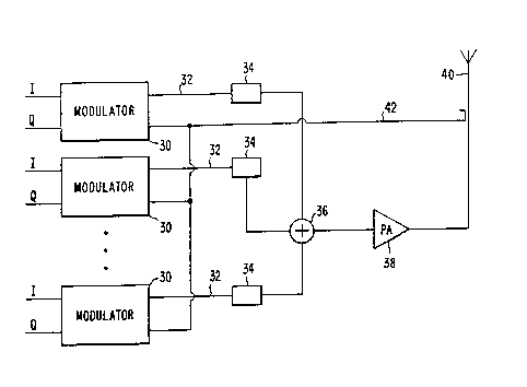
Thus, according to an exemplary embodiment
of the present invention, illustrated in Figure 3, a
transmission system has been designed wherein the
combiner has been eliminated. m e operation of this
system is as follows.
In a ~anner similar to that used to
illustrate the conventional syste~ of Figure 1, only
three branches are shown in the illustrative block
diagram of this exemplary embodiment of the present
inve~tion, however, those skilled in the art will
readily appreciate that such a system can have as many
bran~hes as necessary to correspond to the number of ~;
channels used in the system. Again, the operation o~ a
~ingle branch will be described as operation of the
other channel branches is similar thereto.
The baseband quadrature components I and Q
are input to the modulator 30 wherein the components
are upconverted to a predetermined rf transmission
freguency assigned to the corre5pondin~ channel and
su~mea thereafter. This signal is output on line 32 to
the phase compensator at block 34 where the phase of
each channel signal is adjusted prior to summation.
Although the phase compensator 34 has been illustrated
wos4ll7S9g PCT/~ 4/0~36
-6-
in the exemplary embodiments as a separate element, the
phase compensators could also be formed integrally with ~-
the modulators 30. The resultant signal is summed at
block 36 with the same signals of the other channels.
This composite signal is then amplified by the rf power
amplifier 38 before being transmitted via antenna 40.
A cartesian feedback loop 42 samples the combined,
~ulti-carrier signal which is then demodulated and
compared with the reference baseband components in each
of the modulators 30 in the same manner in which the
single carrier output signal was processed as described
above with respect to Figure 2.
Thus, according to this exemplary
embodiment, the forward transmission circu~t need not
be highly linear because linearity is provided by the
cartesian feedback loop, which is readily accomplished
since very little power needs to be amplified in the
feedback loop. In this way, ~ntermsdul~tion between
the various carrier frequencies is suppressed. For
20 example, without the cartesian feedback loop, signals -~
having two different carrier freguencies, f1 and f2,
which were summed and input to ~ nonlinear rf power
~plifier would output a ~ignal having æignificant
intermodulation. m e output of the nonlinear amplifier
wculd comprise, for example, frequencies fl, f2, 2f--f2
2f2-f1~ 3f1-2f2, 3f2-2f1, etc.
With the provision of the cartesian feedback
loop which provides feedbacX on every possible
intermodulation frequency, however, the intermodulation
is suppressed by the gain in the cartesian feedback
loop. Thus, if the carrier frequencies have
approximately the same separation over the total
transmitted bandwidth there iæ no need for the -
provision of a co~biner.
.... . . ~ , , ... ,. ~ ; ., .
y~og4l17~ PCTISE94/0~36
~ ;~ 6~ b ~
--7--
Figure 4 illustrates this feature of
exemplary embodiments of thie present invention by
showing the bandwidth of the separated carrier
frequencies as compared to the cartesian feedback loop
bandwidth. The outer dotted line 50 represents a
bandpass filter which excludes frequencies outside
those used by the base stat~on. The frequency spectrum
for each channel ~ignal is shown as centered about its
corresponding carrier fxequency, for example the
frequency ~pectrum 52 relative to frequency f1. The
~dotted lines 54 which surround each frequency spectrum
denote the loop gain of the feedback loop. Note that
the bandwidth 56 of the cartesian feedback loop is such
that any intermodulation frequencies (e.g., frequencies
between f1 and f2) would be suppressed by the loop
g~in.
According to another embodiment, shown in
Figure 5 where the same reference numbers used in -~
Figure 4 are again used to identify similar features,
the bandwidth of the feedback cian be varied such that
the loop bandwidths overlap at their edges. This can
provide, for exa~ple, more freedom ~n ~arying the
~ep~rat~on between carrier frequencies while still
suppressing intermodulation.
~nother exemplary embodiment of the present
invention is illustrated in Figure 6 in which similar
reference numerals are used to identify simllar
ele~ients. This transmission system is identical to the
system of Figure 3 except that the reference baseband
components are not upconverted to the transmission
freguenc~ in the modulators 10 nor is the feedback
sign~l downconverted from the transmission frequency in
the modulators 10. Incitead, a downconverter 43 is
placed in the feedback loop after sampling of the
output signal and an up~onverter 44 is placed after the
W094117599 PCT/~4/OH~6
,~
~ i ~ 2 ~
-8-
summation block 36 and before the power amplifier 38.
Thus, modulators 10 upconvert to, and downconvert from,
an intermediate frequency. This maXes implementation
of a 90 degree phase shift network in quadrature
modulators more easily acco~plished and also generally
reduces interferencey. The exemplary waveforms of
Figures 4 and 5 can also be achieved using this
exemplary embodimant and the discussion set forth above
is equally relevant thereto.
Althouqh the present invention has ~een
described by way of the foregoing exemplary
embodiments, it will be appreciated by those skilled in
the art that the present invention can be embodied in
other forms without departing from the spirit or
essential character thereof. Thus, for example, other
types of adaptive feedback techniques could be -~
substituted for the cartesian feedback loop used in the
exemplary embodiments described herein. Moreover, ~ -
although the overall systems (e.g., base station) in
which transmission systems according to the present
invention can be used have not been described in
detail, the present ~nvention is intended to encompass
the incorporation of the present invention therein.
Thus, for example, the present invention readily lends -
itself to incorporation in any multicarrier
transmission system, including FDMA syst~ms and multi-
carrier TDMA and CDMA systems. An exemplary system is
disclosed in U.S. Patent No. 5,140,627, entitled
"Handoff Procedure that Minimizes Disturbance to DTNF
Signalling in a Cellular Radio Systemn, which is hereby
incorporated by reference.
The presently disclosed embodiments are
therefore considered in all respects to be illustrative
and not restrictive. The scope of the invention is
indicated by the appended claims rather than the
. . .
..... . - , : ~
~ 0 ~/17599 PCr~4/~36
~, ~ s~ 3
g
foregoing description, and all changes which come
within the meaning and range of eguivalents thereof are
intended to be embraced therein.