Sélection de la langue

Search

Sommaire du brevet 2132600 

Énoncé de désistement de responsabilité concernant l'information provenant de tiers

Une partie des informations de ce site Web a été fournie par des sources externes. Le gouvernement du Canada n'assume aucune responsabilité concernant la précision, l'actualité ou la fiabilité des informations fournies par les sources externes. Les utilisateurs qui désirent employer cette information devraient consulter directement la source des informations. Le contenu fourni par les sources externes n'est pas assujetti aux exigences sur les langues officielles, la protection des renseignements personnels et l'accessibilité.

Disponibilité de l'Abrégé et des Revendications

L'apparition de différences dans le texte et l'image des Revendications et de l'Abrégé dépend du moment auquel le document est publié. Les textes des Revendications et de l'Abrégé sont affichés :

  • lorsque la demande peut être examinée par le public;
  • lorsque le brevet est émis (délivrance).
(12) Brevet: (11) CA 2132600
(54) Titre français: PARAPLUIE AUTOMATIQUE A BOUTON DE COMMANDE BIDIRECTIONNEL COMPORTANT UN DISPOSITIF DE SECURITE
(54) Titre anglais: RELIABLY OPERATED AUTOMATIC UMBRELLA WITH UPWARDLY AND DOWNWARDLY THRUSTED PUSH BUTTON
Statut: Périmé et au-delà du délai pour l’annulation
Données bibliographiques
(51) Classification internationale des brevets (CIB):
  • A45B 25/14 (2006.01)
(72) Inventeurs :
  • LIN, CHUNG-KUANG (Taïwan, Province de Chine)
  • CHANG, JUNG-JEN (Taïwan, Province de Chine)
(73) Titulaires :
  • FU TAI UMBRELLA WORKS, LTD.
(71) Demandeurs :
  • FU TAI UMBRELLA WORKS, LTD. (Taïwan, Province de Chine)
(74) Agent: SMART & BIGGAR LP
(74) Co-agent:
(45) Délivré: 1999-01-19
(22) Date de dépôt: 1994-09-21
(41) Mise à la disponibilité du public: 1995-11-04
Requête d'examen: 1996-06-25
Licence disponible: S.O.
Cédé au domaine public: S.O.
(25) Langue des documents déposés: Anglais

Traité de coopération en matière de brevets (PCT): Non

(30) Données de priorité de la demande:
Numéro de la demande Pays / territoire Date
08/237,873 (Etats-Unis d'Amérique) 1994-05-03

Abrégés

Abrégé français

Parapluie automatique comprenant un manche central à liaison pivotante et comportant une multitude de nervures et une poignée coulissant dans le plan vertical, fixée au moyen d'un bouton poussoir, ladite poignée pouvant être poussée vers le haut pour provoquer l'ouverture du parapluie par l'action d'un ressort d'ouverture maintenu dans le manche, et laquelle poignée peut être poussée vers le bas pour fermer le parapluie par l'action d'un ressort de fermeture, afin d'éviter la confusion ou une fausse manoeuvre à l'ouverture ou à la fermeture du parapluie.


Abrégé anglais


An automatic umbrella includes a central shaft pivotally
secured with a plurality of ribs on the shaft and a handle
vertically slidably secured with a push button which can be
pushed upwardly for opening the umbrella as urged by an opening
spring retained in the shaft and may be pushed downwardly for
closing the umbrella as effected by a closing spring retained in
the shaft for preventing a confusing or false operation when
extending or folding the umbrella.

Revendications

Note : Les revendications sont présentées dans la langue officielle dans laquelle elles ont été soumises.


THE EMBODIMENTS OF THE INVENTION IN WHICH AN EXCLUSIVE
PROPERTY OR PRIVILEGE IS CLAIMED ARE DEFINED AS FOLLOWS:
1. An automatic umbrella comprising:
a central shaft means (1) including: an inner tube (11)
secured to a handle (12), a middle tube (13) slidably externally
disposed about the inner tube (11), an outer tube (14) slidably
externally disposed about the middle tube (13), and a top sleeve
(15) slidably held in a top portion of the middle tube (13);
an umbrella rib means (2) including: a plurality of top ribs
(21) with an inner end of each top rib (21) pivotally secured to
an upper runner (22) fixed on the top sleeve (15), a plurality of
intermediate ribs (23) with an inner end of each intermediate rib
(23) pivotally connected with a middle runner (24) fixed on an
upper portion of the middle tube (13) and with an outer end of
each intermediate rib (23) pivotally connected to each top rib
(21), a plurality of stretcher rib (25) with an inner end of each
stretcher rib (25) pivotally secured to a lower runner (26)
slidably externally held on the outer tube (14) and with an outer
end of each stretcher rib (25) pivotally connected to each top
rib (21), and a hook member (261) pivotally mounted in the lower
runner (26) and engageable with a lower hook hole (134) formed in
the middle tube (13) for closing an umbrella;
an umbrella-opening spring (3) having a lower spring end
(31) retained on an upper portion (130) of the middle tube (13)
and an upper spring end (32) retained on a bottom portion of the
top sleeve (15);
an umbrella-closing spring (4) having a lower spring end
(41) retained on an upper end portion (110) of the inner tube
(11) and an upper spring end (42) retained on a middle retainer

(131) of the middle tube (13); and
a control means (5) including: a push button (51) vertically
slidably held in the handle (12) with a resilient pawl (513)
pivotally resiliently mounted in the push button (51) by a pawl
spring (513a), a lower control sleeve (52) coupled to the inner
tube (11) by a spring catch (520), a lateral pin (512) protruding
laterally from said push button (51) to be connected to the lower
control sleeve (52), a plug (53) having a linking rod (531)
protruding upwardly from the plug (13) and slidably held in the
inner tube (11), an upper control sleeve (54) connected to the
linking rod (531) of the plug (53) and having a convex portion
(541) protruding laterally outwardly from the upper control
sleeve (54) for outwardly thrusting and disengaging the hook
member (261) pivotally mounted on the lower runner (26) for
opening an umbrella from its closed state when the push button
(51) is upwardly thrusted to raise the lower control sleeve (52)
so as to raise the plug (53) and the upper control sleeve (54),
a biasing lever (58) pivotally mounted in a lower portion of the
inner tube (11), an upper hook portion (581) of said biasing
lever (58) passing through the lower control sleeve (52) and the
inner tube (11) for engaging a hook hole (133) formed in the
middle tube (13) for coupling the middle tube (13) with the inner
tube (11) for compressing the umbrella-closing spring (4)
retained between the middle tube (13) and the inner tube (11), a
lower rod portion (582) of said biasing lever (58) protruding
outwardly from said lever (58) opposite to said upper hook
portion (581) to be operatively depressed by the resilient pawl

(513) when downwardly thrusting the push button (51) for
disengaging the upper hook portion (581) of the biasing lever
(58) from the hook hole (133) in the middle tube (13) for
uncoupling the middle tube (13) from the inner tube (11) for
releasing the umbrella-closing spring (4) for closing the
umbrella from an opened state thereof, and a resilient retainer
(57) protruding laterally from the upper control sleeve (54) to
be resiliently held in an inside wall of the middle tube (13) for
stably operating the upper control sleeve (54) in the middle tube
(13) of the umbrella;
the improvement which comprises:
said control means (5) including a safety bifurcate member
(143) retained on a lower portion of said outer tube (14)
normally retarding said resilient pawl (513) from depressing the
lower rod portion (582) of said biasing lever (58) before the
umbrella being opened, said safety bifurcate member (143)
operatively raised to allow a depression of said resilient pawl
(513) on said lower rod portion (582) of said biasing lever (58)
ready for closing an opened umbrella after opening the umbrella;
and
said middle tube (13) formed with an upper recess (135)
converging inwardly in an upper portion of said middle tube (13)
adjacent to the hook member (261) of said lower runner (26) when
the umbrella is opened, whereby upon a downwardly moving of said
rib means (2) subjected to a downward wind pressure, said hook
member (261) will be temporarily engaged into the upper recess
(135) in the middle tube for a buffer of the wind pressure.
2. An automatic umbrella according to Claim 1, wherein said

outer tube (14) is formed a crimped flange (140) on a top edge
portion of said outer tube (14), said crimped flange (140)
operatively raised by said lower runner (26), when opening the
umbrella from a closing state thereof, to raise said outer tube
(14) and said safety bifurcate member (143) ready for a closing
of an opened umbrella.
11

Description

Note : Les descriptions sont présentées dans la langue officielle dans laquelle elles ont été soumises.

~13~60~
Title: Reliably Operated Automatic Umbrella with Upwardly and
Downwardly Thrusted Push Button
Background of the Invention:
A conventional automatic umbrella is provided with a push
button having an upper button portion which is depressed for
opening the umbrella and a lower button portion which is
depressed for closing the umbrella. Whenever opening or closing
the umbrella, the umbrella user should be very careful to watch
the marking or position of the upper or lower button portion.
Otherwise, he or she may depress the false button portion to
influence the operation of the umbrella. If it is dark or at
night time, the vision is too unclear to distinguish the location
of the upper or lower button portion, confusing the umbrella
opening or closing operation and causing inconvenience therefor.
The present inventor has found the drawbacks of a
conventional automatic umbrella and invented the present
umbrella for a clearer operation for opening or closing the
umbrella.
Summary of the Invention:
The object of the present invention is to provide an
automatic umbrella including a push button which may be pushed
upwardly for opening the umbrella and may be pushed downwardly
for closing the umbrella for preventing a confusing or false
operation when extending or folding the umbrella.
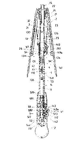
Brief Description of the Drawings:

~132600
Figure 1 is an illustration showing a closed umbrella when
folded from Figure 6.
Figure 2 shows a resilient retainer of an upper control
sleeve in accordance with the present invention.
Figure 3 shows a closed umbrella when resetting a closing
spring of the umbrella.
Figure 4 is an illustration showing an instantly operating
condition when opening the umbrella in accordance with the
present invention.
Figure 5 is a partial enlarged view from Figure 4 of the
present invention.
Figue 6 is an illustration showing an opened umbrella of the
present invention.
Figure 7 is a partial enlarged view from Figure 6 of the
present invention.
Detailed Description:
As shown in the drawing figures, the present invention
comprises: a central shaft means 1, an umbrella rib means 2, an
umbrella-opening spring 3, an umbrella-closing spring 4, and a
control means 5.
The central sh2ft means 1 includes: an inner tube 11 having
a lower end portion of the inner tube 11 secured to a handle 12,
a middle tube 13 slidably externally disposed about the inner
tube 11, an outer tube 14 slidably externally disposed about the
middle tube 13, and a top sleeve 15 slidably held in the middle
tube 13.

2132600
The umbrella rib means 2 includes: a plurality of top ribs
21 having an inner end of each top rib 21 pivotally secured to an
upper runner 22 fixed on the top sleeve 15, a plurality of
intermediate ribs 23 having an inner end of each intermediate rib
23 pivotally connected with a middle runner 24 fixed on an upper
portion of the middle tube 13 and having an outer end of each
intermediate rib 23 pivotally connected to each top rib 21, and a
plurality of stretcher rib 25 having an inner end of each
stretcher rib 25 pivotally secured to a lower runner 26 slidably
externally held on the outer tube 14 and having an outer end of
each stretcher rib 25 pivotally connected to each top rib 21,
with the lower runner 26 having a hook member 261 pivotally
mounted in the lower runner 26 and engageable with a lower hook
hole 134 formed in the middle tube 13 for closing an umbrella.
The umbrella-opening spring 3 has a lower spring end 31
retained on an upper portion 130 of the middle tube 13 and an
upper spring end 32 retained on a kottom portion of the top
sleeve 15.
The umbrella-closing spring 4 has a lower spring end 41
retained on an upper end portion 110 of the inner tube 11 and an
upper spring end 42 retained on a middle retainer 131 of the
middle tube 13.
The control means 5 includes: a push button 51 vertically
slidably held in the handle 12, a resilient pawl 513 pivotally
resiliently mounted in the push button 51 by a pawl spring 513a,
a lower control sleeve 52 coupled to the inner tube 11 by a
spring catch 520, a lateral pin 512 protruding laterally towards
a center of the central shaft means 1, through a lower slot 142

~13260~
formed in a lower portion of the outer tube 14 and a pin slot 112
formed in a lower portion of the inner tube 11, to be connected
to the lower control sleeve 52, a plug 53 having a linking rod
531 protruding upwardly from the plug 13 and slidably held in the
inner tube 11, an upper control sleeve 54 connected to the linkig
rod 531 of the plug 53 and having a convex portion 541 protruding
laterally outwardly from the upper control sleeve 54 for
outwardly thrusting and disengaging the hook member 261 pivotally
mounted on the lower runner 26 for opening an umbrella from its
closed state upon an upwardly thrusting of the push button 51 to
raise the lower control sleeve 52, the plug 53 and the upper
control sleeve 54, and a biasing lever 58 pivotally mounted in a
lower portion of the inner tube 11 and having an upper hook
portion 581 passing through the lower ccntrol sleeve 52 and the
inner tube 11 for engaging a hook hole 133 formed in the middle
tube 13 for coupling the middle tube 13 with the inner tube 11
for compressing the umbrella-closing spring 4 retained between
the middle tube 13 and the inner tube 11 and having a lower rod
portion 582 passing through the lower control sleeve 52, the
inner tube 11 and the outer tube 14 to be operatively depressed
by the resilient pawl 513 when downwardly thrusting the push
button 51 for disengaging the upper hook portion 581 of the
biasing lever 58 from the hook hole 133 in the middle tube 13 for
uncoupling the middle tube 13 from the inner tube 11 for
releasing the umbrella-closing spring 4 for closing the umbrella
from an opened state thereof.
The upper control sleeve 54 includes a resilient retainer 57

, X1~2600
protruding laterally from the upper control sleeve 54 to be
resiliently held in an inside wall of the middle tube 13 for
stably operating the upper control sleeve 54 in the middle tube
13 of the umbrella.
In operating the present invention for opening the umbrella
as shown in Figure 6 from a closed state as shown in Figure 3,
the push button 51 is thrusted upwardly to raise the lower
control sleeve 52, the plug 53 and linking rod 531 and upper
control sleeve 54 to allow the protruding convex portion 541 to
disengage the hook member 261 of the lower runner 26 from a lower
hook hole 134 notched in the middle tube 13 to release the
umbrella-opening spring 3, thereby raising the top sleeve 15, the
rib means 2 and the lower runner 26 until the hook member 261 is
engaged with an upper edge 141a of the hook hole 141 recessed in
the outer tube 14. ~he pawl 513 will be moved to be above the
lower rod portion 582.
The middle tube 13 is formed with an upper recess 135
converging inwardly in an upper portion of the middle tube 13
adjacent to the hook member 261 of the lower runner 26 to
temporarily engage the hook member 261 of the lower runner 26
when an umbrella cloth 20 is subjected to a wind pressure W as
shown in Figure 6 for a buffer of the wind pressure W to prevent
damage to the umbrella.
Whenever the lower runner 26 is raised upon the opening of
the umbrella to push a crimping flange 140 formed on a top edge
portion of the outer tube 14, the outer tube 14 is pulled
upwardly to thereby raise a safety bifurcate member 143, of which
two bifurcated arms 143a are slidably engageable with the lower

~132600
rod portion 5i32 of the biasing lever 58 and normally retards the
resilient pawl 513 from contacting the lower rod portion 582 to
prevent an unexpected closing of an opening umbrella due to a
false depression of the lower rod portion 582 by the resilient
pawl 513 of the push button 51 when opening the umbrella, in
order to release the safety bifurcate member 143 for an umbrella
closing operation from its opened state.
When closing the opened umbrella from Figure 6 to be a
folded situation as shown in Figure 1, the push button 51 is
thrusted downwardly to allow the pawl 513 to depress the lower
rod portion 582 of the biasing lever 58 to disengage the upper
hook portion 581 from the hook hole 133 of the middle tube 13, to
thereby release the compressed umbrella-closing spring 4 to raise
the middle tube 13, the middle runner 24 to close the rib means 2
and to lower the runner 26 to allow the hook member 261 (sliding
along the hook hole 141 longitudinally formed in the outer tube
14~ to re-engage the lower hook hole 134 recessed in the middle
tube 13 as shown in Figure 1. The upper control sleeve 54 is
also raised by an upper edge portion 131a of the middle retainer
131 of the middle tube to allow the convex portion 541 of the
upper control sleeve 54 to approximate the hook member 261 of the
lower runner 26 engaged into the lower hook hole 134 of the
middle tube 13 ready for a next umbrella opening operation by
disengaging the hook member 261 as outwardly thrusted by the
convex portion 541. The closing of the umbrella will also
compress the umbrella-opening spring 3 to store its resilience
energy ready for a next umbrella opening.

~132600
The handle 12 may then be depressed upwardly towards the top
sleeve 15 and the middle tube 13 from Figure 1 to Figure 3 to
compress the umbrella-closing spring 4 for restoring its energy
ready for next closing use. The hook hole 133 of the middle tube
13 will be engaged with the upper hook portion 581 of the biasing
lever S8 as shown in Figure 3 for "locking" the umbrella-closing
spring 4 at its compressed state.
When re-setting the umbrella-closing spring 4 as shown in
Figure 3 by depressing the handle 12 towards the top sleeve 15
and the middle tube 13, the outer tube 4 with the safety
bifurcate member 143 retained thereon will be lowered to allow
the safety bifurcate member 143 to shield the lower rod portion
582 of the biasing lever 58 to prevent a false depression on the
biasing lever 58 to unexpectedly close an opened umbrella when
instantly opening an umbrella as shown in Figures 4 and 5. The
reciprocal movement of the outer tube 14 on the inner tube 11 may
be guided by a pin 144 laterally secured on a lower portion of
the outer tube 14 and slidably engageable in an elongate slot 111
cut in a lower portion of the inner tube 11.
The present invention provides a logical operation sequence
without causing confusion in opening or closing the umbrella
since an upwardly thrusting of the push button 51 will open the
umbrella and a downwardly thrusting of the button 51 will close
the umbrella.

Dessin représentatif
Une figure unique qui représente un dessin illustrant l'invention.
États administratifs

2024-08-01 : Dans le cadre de la transition vers les Brevets de nouvelle génération (BNG), la base de données sur les brevets canadiens (BDBC) contient désormais un Historique d'événement plus détaillé, qui reproduit le Journal des événements de notre nouvelle solution interne.

Veuillez noter que les événements débutant par « Inactive : » se réfèrent à des événements qui ne sont plus utilisés dans notre nouvelle solution interne.

Pour une meilleure compréhension de l'état de la demande ou brevet qui figure sur cette page, la rubrique Mise en garde , et les descriptions de Brevet , Historique d'événement , Taxes périodiques et Historique des paiements devraient être consultées.

Historique d'événement

Description Date
Le délai pour l'annulation est expiré 2002-09-23
Lettre envoyée 2001-09-21
Accordé par délivrance 1999-01-19
Préoctroi 1998-09-30
Inactive : Taxe finale reçue 1998-09-30
Un avis d'acceptation est envoyé 1998-06-11
Lettre envoyée 1998-06-11
Un avis d'acceptation est envoyé 1998-06-11
Inactive : Renseign. sur l'état - Complets dès date d'ent. journ. 1998-06-09
Inactive : Dem. traitée sur TS dès date d'ent. journal 1998-06-09
Inactive : CIB attribuée 1998-05-02
Inactive : CIB enlevée 1998-05-02
Inactive : CIB en 1re position 1998-05-02
Inactive : Approuvée aux fins d'acceptation (AFA) 1998-04-30
Exigences pour une requête d'examen - jugée conforme 1996-06-25
Toutes les exigences pour l'examen - jugée conforme 1996-06-25
Demande publiée (accessible au public) 1995-11-04

Historique d'abandonnement

Il n'y a pas d'historique d'abandonnement

Taxes périodiques

Le dernier paiement a été reçu le 1998-08-11

Avis : Si le paiement en totalité n'a pas été reçu au plus tard à la date indiquée, une taxe supplémentaire peut être imposée, soit une des taxes suivantes :

  • taxe de rétablissement ;
  • taxe pour paiement en souffrance ; ou
  • taxe additionnelle pour le renversement d'une péremption réputée.

Veuillez vous référer à la page web des taxes sur les brevets de l'OPIC pour voir tous les montants actuels des taxes.

Historique des taxes

Type de taxes Anniversaire Échéance Date payée
TM (demande, 3e anniv.) - générale 03 1997-09-22 1997-07-30
TM (demande, 4e anniv.) - générale 04 1998-09-21 1998-08-11
Taxe finale - générale 1998-09-30
TM (brevet, 5e anniv.) - générale 1999-09-21 1999-06-28
TM (brevet, 6e anniv.) - générale 2000-09-21 2000-06-30
Titulaires au dossier

Les titulaires actuels et antérieures au dossier sont affichés en ordre alphabétique.

Titulaires actuels au dossier
FU TAI UMBRELLA WORKS, LTD.
Titulaires antérieures au dossier
CHUNG-KUANG LIN
JUNG-JEN CHANG
Les propriétaires antérieurs qui ne figurent pas dans la liste des « Propriétaires au dossier » apparaîtront dans d'autres documents au dossier.
Documents

Pour visionner les fichiers sélectionnés, entrer le code reCAPTCHA :


Pour visualiser une image, cliquer sur un lien dans la colonne description du document. Pour télécharger l'image (les images), cliquer l'une ou plusieurs cases à cocher dans la première colonne et ensuite cliquer sur le bouton "Télécharger sélection en format PDF (archive Zip)" ou le bouton "Télécharger sélection (en un fichier PDF fusionné)".

Liste des documents de brevet publiés et non publiés sur la BDBC .

Si vous avez des difficultés à accéder au contenu, veuillez communiquer avec le Centre de services à la clientèle au 1-866-997-1936, ou envoyer un courriel au Centre de service à la clientèle de l'OPIC.


Description du
Document 
Date
(aaaa-mm-jj) 
Nombre de pages   Taille de l'image (Ko) 
Page couverture 1999-01-08 2 60
Page couverture 1996-02-14 1 18
Abrégé 1995-11-04 1 14
Description 1995-11-04 7 280
Dessins 1995-11-04 4 148
Revendications 1995-11-04 4 145
Dessin représentatif 1998-07-09 1 28
Dessin représentatif 1999-01-08 1 16
Avis du commissaire - Demande jugée acceptable 1998-06-11 1 164
Avis concernant la taxe de maintien 2001-10-22 1 178
Taxes 1999-06-28 1 28
Taxes 1998-08-11 1 41
Correspondance 1998-09-30 1 37
Taxes 1997-07-30 1 32
Taxes 2000-06-30 1 30
Taxes 1996-06-26 1 36
Correspondance de la poursuite 1994-09-21 3 131
Courtoisie - Lettre du bureau 1996-07-18 1 49
Correspondance de la poursuite 1996-06-25 2 47