Sélection de la langue

Search

Sommaire du brevet 2132606 

Énoncé de désistement de responsabilité concernant l'information provenant de tiers

Une partie des informations de ce site Web a été fournie par des sources externes. Le gouvernement du Canada n'assume aucune responsabilité concernant la précision, l'actualité ou la fiabilité des informations fournies par les sources externes. Les utilisateurs qui désirent employer cette information devraient consulter directement la source des informations. Le contenu fourni par les sources externes n'est pas assujetti aux exigences sur les langues officielles, la protection des renseignements personnels et l'accessibilité.

Disponibilité de l'Abrégé et des Revendications

L'apparition de différences dans le texte et l'image des Revendications et de l'Abrégé dépend du moment auquel le document est publié. Les textes des Revendications et de l'Abrégé sont affichés :

  • lorsque la demande peut être examinée par le public;
  • lorsque le brevet est émis (délivrance).
(12) Brevet: (11) CA 2132606
(54) Titre français: DISPOSITIF DESTINE A UN TUBE GUIDE DE CABLE DE TRACTION
(54) Titre anglais: DEVICE FOR A CURVED CONDUCTOR PIPE FOR A PULL WIRE
Statut: Durée expirée - au-delà du délai suivant l'octroi
Données bibliographiques
(51) Classification internationale des brevets (CIB):
  • E21B 17/00 (2006.01)
  • E21B 43/013 (2006.01)
(72) Inventeurs :
  • HYSTAD, PER H. (Norvège)
(73) Titulaires :
  • KARMOY WINCH A/S
(71) Demandeurs :
  • KARMOY WINCH A/S (Norvège)
(74) Agent: SMART & BIGGAR LP
(74) Co-agent:
(45) Délivré: 2004-11-23
(22) Date de dépôt: 1994-09-21
(41) Mise à la disponibilité du public: 1995-04-09
Requête d'examen: 2001-09-21
Licence disponible: S.O.
Cédé au domaine public: S.O.
(25) Langue des documents déposés: Anglais

Traité de coopération en matière de brevets (PCT): Non

(30) Données de priorité de la demande:
Numéro de la demande Pays / territoire Date
933605 (Norvège) 1993-10-08

Abrégés

Abrégé français

Un dispositif (5) destiné à un tube guide (8) de câble de traction (4) dans lequel le tube guide (8) est fourni le long de l'intérieur de celui-ci avec un revêtement (9; 10, 11, 12, 13) présentant un point limite d'élasticité supérieur à la force de compression qui agit entre le revêtement (9; 10, 11, 12, 13) et le câble de traction (4). Le revêtement (9; 10, 11, 12, 13) est équipé d'un siège de guide (14) pour le câble de traction (4) pour pouvoir répartir la force de compression à partir du câble de traction (4) sur le revêtement (9; 10, 11, 12, 13).


Abrégé anglais

A device (5) for a curved conductor pipe (8) for a pull wire (4) wherein the conductor pipe (8) is provided along the inside thereof with a lining (9; 10, 11, 12, 13) which has a material yield point that is higher than the compressive force that operates between the lining (9; 10, 11, 12, 13) and the pull wire (4) . The lining (9; 10, 11, 12, 13) is equipped with a guide seat (14) for the pull wire (4) in order to distribute the compressive force from the pull wire (4) over the lining (9; 10, 11, 12, 13).

Revendications

Note : Les revendications sont présentées dans la langue officielle dans laquelle elles ont été soumises.


Claims:
1. A lining assembly for a longitudinally archingly curved conductor pipe
of a given hardness and given internal diameter, for a pull wire, which, when
pulled longitudinally of the pipe while housed by the pipe would, absent said
lining assembly, tend to abradingly, rubbingly engage an inner peripheral wall
surface of the pipe along a longitudinal path which extends along an inner
side of a longitudinally arched curve of the pipe so as to exert a compression
force transversely of said pipe on said surface in said path, which, absent
said
lining assembly, would tend to cut into said pipe along said path,
said lining assembly comprising:
a plurality of longitudinally adjoining individually cast tubular sections
serially lining corresponding portions of said inner peripheral wall of
said pipe;
said lining sections each having an inner peripheral surface defining
respective portions of a guide seat recess which extends along said
path to provide a contact face for said wire;
said lining sections being thicker within and laterally adjacent said
guide seat portions, than diametrically opposite said guide seat
portions; and
said lining sections being made of a material which is harder than and
less subject to being abradingly worn by longitudinal pulling of said wire
than would be said inner peripheral surface of said pipe were said
lining assembly absent.
2. The lining assembly of claim 1, wherein:

each said section of said lining assembly has a radially outer peripheral
surface which is approximately circular in transversecross-sectional
figure; and
said inner peripheral surface of each said section of said lining
assembly, excepting said guide seat recess, is approximately circular
in transverse cross section.
3. The lining assembly of claim 1, wherein:
said lining assembly includes terminal ones of said sections at opposite
ends thereof, each said terminal section, at effectively opposite ends of
said lining assembly having a respective radially outwardly extending
flange; said flanges being greater in diameter than said given diameter
and being arranged to respectively engage opposite ends of said pipe
for longitudinally fixing said lining assembly relative to said pipe.

Description

Note : Les descriptions sont présentées dans la langue officielle dans laquelle elles ont été soumises.

X132606
DEVICE FOR A CURVED CONDUCTOR PIPE FOR A PULL WIRE
The present invention relates to a device for a curved
conductor pipe for a pull wire.
In a known conductor pipe of this kind, the material yield
point of the conductor pipe is equal to or less than the
compressive force which operates between the pull wire and the
conductor pipe.
When oil production platforms are set up, large gas/oil pipes
are pulled into couplers at the bottom of the platforms. To
pull these pipes, a pull wire is used which is fed through
~5 a conductor pipe that is connected in a watertight manner to~
the gas/oil pipe coupler. The conductor pipe continues
upwards into the platform shaft to a level above the surface
of the water. The conductor pipe would normally always be
made with a curve in the range of 80-90° immediately after the
zo connection to the gas/oil pipe coupler. This means that the
conductor pipe is subjected to great stress, especially in
instances when large gas/oil pipes are pulled into place,
where the traction forces in question may be as much as 300-
500 tonnes.
Normally the conductor pipe is made of a weldable steel of the
St52-3 type or similar. This quality is chosen inter alia for
the following reasons:
3o Good extension properties which provide ample protection
against local peak loads and cracking.
Good welding properties which provide a secure welded
connection of flanges and fixing equipment.
The pipe quality is a standard commodity and lends itself
to induction bending of curves.

i I i
CA 02132606 2002-09-05
2
However, the recited steel quality has a major disadvantage
for precisely the purpose as outlined above for which the
steel is used in conductor pipes for pulling oil/gas pipes in
connection with oil/gas installations. The pipe has a Brinell
s hardness in the range of 180-200. A further disadvantage is
that a pull wire will not have a sufficently good seat when
it is pulled through a curved conductor pipe of this kind.
This is due to the contact face against the bend of the pipe
being extremely small, virtually tangential, which in turn
results in the compressive force between the wire and the
curved conductor pipe rapidly exceeding the yield point of the
conductor pipe (approx. 3,500 kg/cm2).
These last-mentioned factors will in turn result in the,
rasping away of steel material in the conductor pipe where the
wire slides, and consequently a greatly increasing friction
quotient between the conductor pipe and the pull wire. In
turn, this leads to reduced net hoisting power, since a great
part of the winch power which is used to pull in the wire is
ao used not least to overcome the friction between the conductor
pipe and the pull wire. This results in increased wear and
tear on the conductor pipe, which in turn could result in
breaks in the conductor pipe and, in its most unfortunate
consequence, could result in the platform leg filling up with
z5 sea water.
In accordance with the invention there is provided a lining
assembly for a longitudinally archingly curved conductor
pipe of a given hardness and given internal diameter, for a
3o pull wire, which, when pulled longitudinally of the pipe
while housed by the pipe would, absent said lining
assembly, tend to abradingly, rubbingly engage an inner
peripheral wall surface of the pipe along a longitudinal
path which extends along an inner side of a longitudinally
35 arched curve of the pipe so as to exert a compression force
transversely of the pipe on said surface in said path,
which, absent said lining assembly, would tend to cut into

n
CA 02132606 2002-09-05
2a
the pipe along said path. The lining assembly includes a
plurality of longitudinally adjoining individually cast
tubular sections serially lining corresponding portions of
the inner peripheral wall of the pipe. The lining sections
each have an inner peripheral surface defining respective
portions of a guide seat recess which extends along the
path to provide a contact face for the wire. The lining
sections are thicker within and Laterally adjacent the
guide seat portions, than diametrically opposite the guide
seat portions. The lining sections are made of a material
which is harder than and less subject to being abradingly
worn by longitudinal pulling of the wire than would be the
inner peripheral surface of the pipe were the lining
assembly absent.
The wall thickness of the lining close to the contact
surface between the pull wire and the lining preferably is
greater than the wall thickness furthest away from the
contact surface. Furthermore, it is of advantage to

zl3zso s
3
have the lining
consist of two or more individually cast sections. To reduce
the force per unit of area against the inside of the conductor
pipe, the lining is provided with a guide seat for the pull
wire. '
In cross-section, the inner wall and the outer wall of the
lining are approximately circular. Furthermore, the inner
wall of the conductor pipe is circular in cross-section and
has a radius that is greater than that of the outer wall of
the lining, said conductor pipe being provided at each end
with a flange which prevents the lining from sliding out of
the conductor pipe.
~5 This invention will now be described in more detail with
reference to the attached figures, where
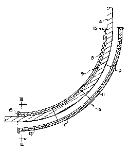
Fig. 1 shows the use of the device according to the present
invention in connection with an oil production platform.
zo
Fig. 2 illustrates the device according to the invention in
connection with feeding a pull wire.
Fig. 3 shows the section III-III in Fig. 2.
Fig. 1 illustrates a production platform consisting of a shaft
1 with a platform part 2 and a winch 3 disposed on said
platform part 2. The winch 3 pulls a wire 4 which is fed
through a conductor pipe device 5 and a production pipe
3o coupler 6 that is known per se connected thereto. The
production pipe 7 is pulled by means of the pull wire 4 into
the coupler 6 where it is secured.
The device 5 is shown in more detail in Fig. 2. It comprises
a conductor pipe 8 that is known per se. A lining is provided
in the conductor pipe, said lining generally designated by
means of reference numeral 9 and which, in the chosen example,

2132606
4
is made of two or more specially cast lining sections,
indicated by the reference numerals 10, 11, 12 and 13
respectively. The outer wall of the sections is circular, but
has a radius that is smaller than that of the inner wall of
the conductor pipe 8 which is also circular in cross-section.
The lining 9, i.e., sections 10, 11, 12 and 13, is equipped
with a seat 14 which is adapted to the diameter of the pull
wire 4, as can be seen in more detail in Fig. 3. This means
that the compressive force that is exerted by the pull wire
on the lining 9 will be distributed over a larger area than
was possible when using the prior art.
According to the invention, it would be an advantage to make.
~5 said sections 10, 11, 12 and 13 , i.e., the lining 9, of a
material of great hardness, preferably with the range of 500-
550 Brinell hardness, which provides a smooth sliding surface
against the wire 4. The selection of such a hard material for
the wire will prevent the wire from being pressed into the
zo lining. Thus, the same amount of friction does not occur as
was caused previously due to the rasping of the wire in the
conductor pipe e.
To ensure that the lining 9 does not slide out or become
z5 displaced relative to the conductor pipe 8, a flange 15 is
attached at each end of the conductor pipe.
As can be seen from Fig. 3, the lining 9 has a thickness o1
dl close to the point of contact between the wire 4 and the
30 lining 9, whilst the wall thickness of the lining at the point
that lies furthest from said point of contact between the wire
and the lining has a lesser thickness of d2. Furthermore,
because the outer radius of the lining 9 is smaller than the
inner radius of the conductor pipe 8, there is a clearance 16
35 between the lining 9 and the conductor pipe 8. A number of
advantages are obtained by means of the present invention in
comparison with the curved conductor pipe that is in use

2.~ 32606
today.
Wear and tear on the conductor pipe, which is caused by filing
when the wire is in motion, is avoided by means of the
s invention. The conductor pipe, equipped with the lining
according to the present invention, will thus maintain full
strength, and ruptures in the pipe will be avoided. Increased
protection against pipe ruptures will consequently provide
increased safety for the operators who install oil/gas pipes.
~o
An additional advantage provided by the present invention is
that the friction between the conductor pipe and the pull wire
will remain at a sufficiently reduced level to make possible
the use of smaller hoisting winches and also wires of a
smaller dimension.
The wear on the pull wire will also be reduced, since the wire
slides against a seat that has a large area and is adapted to
the wire, and said seat is provided with a smooth surface.
zo Said sections 10, 11, 12 and 13, which form the lining 9
according to the present example, in no way limiting for the
invention, will be capable of being used many times for other
hoisting tasks for the pull wire 4, since wear and tear on
these sections is substantially avoided by means of the
z5 present invention.
35

Dessin représentatif
Une figure unique qui représente un dessin illustrant l'invention.
États administratifs

2024-08-01 : Dans le cadre de la transition vers les Brevets de nouvelle génération (BNG), la base de données sur les brevets canadiens (BDBC) contient désormais un Historique d'événement plus détaillé, qui reproduit le Journal des événements de notre nouvelle solution interne.

Veuillez noter que les événements débutant par « Inactive : » se réfèrent à des événements qui ne sont plus utilisés dans notre nouvelle solution interne.

Pour une meilleure compréhension de l'état de la demande ou brevet qui figure sur cette page, la rubrique Mise en garde , et les descriptions de Brevet , Historique d'événement , Taxes périodiques et Historique des paiements devraient être consultées.

Historique d'événement

Description Date
Inactive : Périmé (brevet - nouvelle loi) 2014-09-21
Inactive : CIB de MCD 2006-03-11
Accordé par délivrance 2004-11-23
Inactive : Page couverture publiée 2004-11-22
Inactive : Taxe finale reçue 2004-07-20
Préoctroi 2004-07-20
Un avis d'acceptation est envoyé 2004-03-12
Lettre envoyée 2004-03-12
Un avis d'acceptation est envoyé 2004-03-12
Inactive : Approuvée aux fins d'acceptation (AFA) 2004-03-03
Inactive : CIB en 1re position 2004-02-09
Inactive : CIB enlevée 2004-02-09
Inactive : Grandeur de l'entité changée 2002-09-11
Modification reçue - modification volontaire 2002-09-05
Inactive : Dem. traitée sur TS dès date d'ent. journal 2001-10-18
Lettre envoyée 2001-10-18
Inactive : Renseign. sur l'état - Complets dès date d'ent. journ. 2001-10-18
Toutes les exigences pour l'examen - jugée conforme 2001-09-21
Exigences pour une requête d'examen - jugée conforme 2001-09-21
Demande publiée (accessible au public) 1995-04-09

Historique d'abandonnement

Il n'y a pas d'historique d'abandonnement

Taxes périodiques

Le dernier paiement a été reçu le 2004-08-30

Avis : Si le paiement en totalité n'a pas été reçu au plus tard à la date indiquée, une taxe supplémentaire peut être imposée, soit une des taxes suivantes :

  • taxe de rétablissement ;
  • taxe pour paiement en souffrance ; ou
  • taxe additionnelle pour le renversement d'une péremption réputée.

Les taxes sur les brevets sont ajustées au 1er janvier de chaque année. Les montants ci-dessus sont les montants actuels s'ils sont reçus au plus tard le 31 décembre de l'année en cours.
Veuillez vous référer à la page web des taxes sur les brevets de l'OPIC pour voir tous les montants actuels des taxes.

Historique des taxes

Type de taxes Anniversaire Échéance Date payée
TM (demande, 3e anniv.) - petite 03 1997-09-22 1997-09-05
TM (demande, 4e anniv.) - petite 04 1998-09-21 1998-08-25
TM (demande, 5e anniv.) - petite 05 1999-09-21 1999-09-20
TM (demande, 6e anniv.) - petite 06 2000-09-21 2000-09-19
TM (demande, 7e anniv.) - petite 07 2001-09-21 2001-09-13
Requête d'examen - petite 2001-09-21
TM (demande, 8e anniv.) - générale 08 2002-09-23 2002-08-30
TM (demande, 9e anniv.) - générale 09 2003-09-22 2003-09-04
Taxe finale - générale 2004-07-20
TM (demande, 10e anniv.) - générale 10 2004-09-21 2004-08-30
TM (brevet, 11e anniv.) - générale 2005-09-21 2005-08-30
TM (brevet, 12e anniv.) - générale 2006-09-21 2006-08-21
TM (brevet, 13e anniv.) - générale 2007-09-21 2007-08-21
TM (brevet, 14e anniv.) - générale 2008-09-22 2008-09-08
TM (brevet, 15e anniv.) - générale 2009-09-21 2009-09-01
TM (brevet, 16e anniv.) - générale 2010-09-21 2010-08-23
TM (brevet, 17e anniv.) - générale 2011-09-21 2011-09-02
TM (brevet, 18e anniv.) - générale 2012-09-21 2012-08-23
TM (brevet, 19e anniv.) - générale 2013-09-23 2013-09-05
Titulaires au dossier

Les titulaires actuels et antérieures au dossier sont affichés en ordre alphabétique.

Titulaires actuels au dossier
KARMOY WINCH A/S
Titulaires antérieures au dossier
PER H. HYSTAD
Les propriétaires antérieurs qui ne figurent pas dans la liste des « Propriétaires au dossier » apparaîtront dans d'autres documents au dossier.
Documents

Pour visionner les fichiers sélectionnés, entrer le code reCAPTCHA :


Pour visualiser une image, cliquer sur un lien dans la colonne description du document. Pour télécharger l'image (les images), cliquer l'une ou plusieurs cases à cocher dans la première colonne et ensuite cliquer sur le bouton "Télécharger sélection en format PDF (archive Zip)" ou le bouton "Télécharger sélection (en un fichier PDF fusionné)".

Liste des documents de brevet publiés et non publiés sur la BDBC .

Si vous avez des difficultés à accéder au contenu, veuillez communiquer avec le Centre de services à la clientèle au 1-866-997-1936, ou envoyer un courriel au Centre de service à la clientèle de l'OPIC.


Description du
Document 
Date
(aaaa-mm-jj) 
Nombre de pages   Taille de l'image (Ko) 
Dessin représentatif 1998-03-03 1 13
Dessins 2001-11-08 1 32
Dessins 1995-06-05 1 100
Revendications 1995-06-05 2 113
Description 1995-06-05 5 273
Revendications 2002-09-04 2 56
Dessin représentatif 2004-02-09 1 4
Dessin représentatif 2004-02-19 1 8
Description 2002-09-04 6 211
Abrégé 1995-06-05 1 11
Rappel - requête d'examen 2001-05-22 1 117
Accusé de réception de la requête d'examen 2001-10-17 1 194
Avis du commissaire - Demande jugée acceptable 2004-03-11 1 161
Correspondance 1995-11-14 2 82
Taxes 1998-08-24 1 55
Taxes 1999-09-19 1 49
Taxes 1997-09-04 1 51
Taxes 2000-09-18 1 32
Correspondance 2004-07-19 1 34
Taxes 2004-08-29 1 36
Taxes 1996-09-17 1 51