Note : Les descriptions sont présentées dans la langue officielle dans laquelle elles ont été soumises.
- 21330~6
Fastening system for fastening a face-protection shield
and/or hearing-protection caps to a work helmet
The invention relates to a fastening system, pro-
vided on both sides of a protective helmet, for adjust-
S ably holding a face-protection shield and/or hearing-
protection caps according to the preamble of the indepen-
dent Patent Claim 1.
There are a large number of fields of work in
which a protective helmet having additional hearing
and/or face protection has to be worn, for instance often
in the construction or forestry industries where motor
saws are operated. The personal protection requirements
of the actual persons engaged in the work, as well as
regulations, demand that there are protective helmet~
available which can be worn in combination with the said
protective devices. It is not just a matter here of mere
functionality, but also of wearing and operating comfort.
In order to prevent the protective helmet and the hearing
and face protection from having to be separately mounted,
worn and handled, designs immediately appeared on the
market whereby the additional protective devices were
fastened to the helmet.
A holding fixture is known, which on both sides
of the protective helmet is fixed to the helmet by means
of a screw connection which passes through its wall (German
Offenlegungsschrift 22 60 311; German utility model 73 35 724).
A drawback with this design, apart from the increased
production complexity, is an often inadmissible weakening
of the helmet shell as a result of the two pass-through
bores and any sight-protection to be worn would need to
be put on separately.
Additionally, a holding frame is known which
surrounds the rim of a protective helmet and to which
there are fitted face and hearing protections (DE-GM
75 23 571). In this version, although the piercing of the
helmet shell is avoided, the design is nevertheless very
complex and the handling of the head-protection elements
- helmet, face and hearing protection - in comhination
- 213301~
-- 2 --
proves to be awkward.
Clamping parts have also been developed which
have to be fixed to the helmet rim, the clamping parts
receiving carrying straps for the hearing-protection caps
(German utility model 74 15 619; German patent specification
27 05 348). These clamping parts are relatively simple in terms
of their constructional design, but they are only suitable
for hoiding a carrying strap. The simultaneous attachment
of a face and hearing protection is not possible.
Those fastening devices which are hitherto known
on work helmets for the fixing of face and hearing-
protection elements cannot as a whole be considered
ideal. For this reason, the invention pursues the objec-
tive of providing a fastening system to which both the
carrying straps for a sight protection and the holding
Rtraps for hearing-protection caps can be simultaneously
attached. The handling of the head-protection elements
must prove to be simple and secure. The entire protective
system should also be capable of being used in the
electrical field. Furthermore, the fastening device must
be of a certain robustness and must be adequately pro-
tected against dirt contamination. Moreover, the
constructional deæign has to enable it to be cheaply
produced. For particular applications in which this will
suffice, the fastening system, in a less complex design,
should allow only the reception of a face-protection
shield or of hearing-protection caps.
Thi~ object i9 achieved by the system according
to the invention, as defined in the independent Patent
Claim 1. Preferred embodiments can be obtained from the
dependent patent claims.
To begin with, the invention i5 based upon the
principal application, namely that the fastening system
is designed to hold both the face-protection shield and
35 hearing-protection caps. The new-type fastening system -~
offers considerable advantages over the previous prior
art. The use of a protective helmet equipped with this
fastening system is shown to be advantageous. The rela~
tively small, compact and lighter construction and the
` 2133016
- 3 -
functioning of the system results in an optimtal contact
pressure of the hearing-protection caps in the state in
which they are clamped against the ears, in an improved
unclamping facility - distanced from the ears - and
pivotability in the direction of the back of the head.
Similarly, the pivotability of the face-protection shield
between the two end po~itions "lowered - shielding the
face" and "raised - exposing the face" is also improved.
The constructional design of the fastening sy~tem enables
a balanced weight distribution of the applied protective
devices, so that their stable positioning in the respect-
ive swivel position is guaranteed and no detectable load
variations for the helmet-wearer are obtained. The system
exhibits no metal parts whatsoever, so that a protective
helmet which is thus equipped can also be used in elec-
trical work. The holding and carrying straps for the
hearing-protection caps and the face-protection shield
respectively no longer have to be distinguished on the
basis of left and right parts. In general, the protective
helmet is used both with the applied hearing-protection
caps and with the face-protection shield, for example in
forestry work involving motor saws. For fields of work in
which this combination is unnecessary, the non-required
protective device can be swivelled away using a handle.
The fastening system, by virtue of its capsule-like
construction, i8 ideally protected against dirt contami-
nation and against tampering. There are no parts which
are in any way relatively loosely suspended, for example
a tension spring, which might get lost. Finally, it
should also be cited as an important advantage that the
new fastening system can be produced substantially more
cheaply in comparison to known embodiments.
An illustrative embodiment of the fastening
system according to the invention is described in detail
below with reference to the appended drawings, in which:
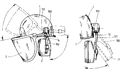
Fig. 1 shows perspective projections displaying protec-
tive devices on the protective helmet; ~ `
la shows a protective helmet displaying applied
hearing-protection caps and an applied
_ 4 _ 213 301 6
face-protection shield in the respective end
positions;
lb shows a hearing-protection cap in clamped and
unclamped position;
5lc shows a hearing-protection cap in rearward-
swivelled position;
Fig. 2 shows representations of the carrying strap
plate, a projection from the X-side displaying a
carrying strap for the face-protection shield;
102a shows a carrying strap in the locked position
"face-protection shield lowered";
2b shows a carrying strap in the locked position
"face-protection shield raised";
2c shows a section according to Figure 2a along the
15line B-B;
Fig. 3 shows representations of the fastening system, a
projection from the Y-side displaying a holding
strap for the hearing-protection cap and a carry-
ing strap for the face-protection shield;
203a shows a perspective projection of the locking
mechanism for the holding strap;
3b shows a sectional reprssentation of the holding
strap in the clamped position;
3c shows a sectional representation of the holding
25strap in the unclamped position;
3d shows an exploded representation, partially cut.
According to Figures la to lc, the protective
helmet 1 exhibits on it~ bottom edge, in the outwardly
extending helmet rim 11 on both sides, a re~pective,
vertically running insertion groove 12 passing through
the helmet rim 11, which insertion groove is surrounded
by upwardly erect bars 13. The insertion grooves 12 are
disposed perpendicularly over the ears of a potential
helmet-wearer. Into the two insertion grooves 12 there is
inserted a respective fastening device 100, to be precise
by an insertion tab 121 extending perpendicularly down-
wards from the fastening device 100, the insertion tab
121 penetrating into the insertion groove 12 from above
and being guided therein. The guidance of the insertion
...: : - ,: ~ .- ~ :- -. . - , . .
........ .. ... . .... .. .
-` 213301~
-- 5 --
ta~ 121 in the insertion groove 12 is reinforced by the
bars 13 surrounding the insertion groove 12, thereby
producing a type of guide sleeve 14. To each fastening
device 100 there is fixed a respective carrying strap 110
5 - the left and right respectively - of the face-protec-
tion shield 2 and a respective holding strap 150 for the
respective left or right hearing-protection cap 3. In
accordance with the momentary requirement~, the face-
protection shield 2 can be lowered (Figure la: continu-
10 ous-line representation) or rai~ed (dashed representa-
tion). The hearing-protection caps 3 can assume three
different po~itions: clamped against the ears of the
wearer (Figures la and lb: continuous-line representa-
tion), unclamped from the ears of the wearer (Figure lb:
15 dashed representation) and, finally, swivelled towards
the rear (Figure la: dashed representation; Figure lc:
continuous-line representation). Locks within the fasten-
ing device 100, which locks shall further be described,
give rise to a stable positioning of the face-protection
20 shield 2 and of the hearing-protection caps 3, 80 that an
unwanted adjustment - e.g. resulting from jerky movements
- is in any event prevented. With a certain force
influence, however, the carrying straps 110 with the
face-protection shield 2 fastened thereto and the holding
25 straps 150 with the hearing-protection caps 3 fixed
thereto are able to be adjusted.
Figures 2a and 2b show the carrying strap plate
120 of the fastening device 100 in the projection X, i.e.
the face facing the protective helmet 1. The sectional
30 representation according to Figure 2c is intended to
illustrate the overall structure of the carrying strap
plate 120. In Figure 2a, the arm 111 of the carrying
strap 110 is lowered, whilst in Figure 2b the arm 111 is
raised. The one-piece carrying strap plate 120 is approx-
35 imately oval in shape and extends downwards as an inser-
tion tab 121 exhibiting the parallel-running side flanks
124. The insertion tab 121 is dimensioned such that the
plug connection between the insertion tab 121 and the
guide sleeve 14 guarantees a secure fixing of the
-- 2133016
-- 6 --
fastening device 100 to the protective helmet 1, but an
occasional withdrawal of the in~ertion tab 121 from the
guide sleeve 14 is also possible with a certain force
expenditure. In the uppermost region and adjacent to the
rim of the carrying strap plate 120, there is mounted in
segment-like fashion, approximately over a radian measure
of 90, a supporting edge 122, which terminates with the
outer flank 125 of the carrying strap plate 120, the
supporting edge 122 extending from the apex line 132
of the carrying strap plate 120 approximately equally far
in both directions. This supporting edge 122 has two
functions. As a result of the supporting edge 122, for
instance, which thickens the uppermost region of the
carrying strap plate 120, the surface curvature of the
protective helmet 1, which surface curvature leads away
from the perpendicularly inserted fastening device 100,
i9 offset. The supporting edge 122 causes the fastening
device 100 to bear in a play-free manner against the
protective helmet. One of the cross-sectional face~ of
the supporting edge 122, namely that which is facing the
transition between the arm 111 and the claw 112 of the
carrying strap 110, serves as a stop 123 whenever the
carrying strap 110 is raised.
From the centre of the carrying strap plate 120
there rises a coupling cam 126 - here having the cross-
sectional shape of a hexagon - which i8 enclasped by the
claw 112 of the carrying strap 110. The coupling cam 126
is of a height corresponding at least to the material
thickness of the claw 112, the material thickness of the
total carrying strap 110 being determined on the ba~is of
the strength requirement and the spatial conditions.
Seated on the coupling cam 126, in the shape of a lid,
there is a holding disc 127; the coupling cam 126 and the
holding disc 127 can expediently form a transition-free
part here. The holding disc 127 has the task of prevent-
ing the claw 112 and hence the total carrying strap 110
from sliding down from the coupling cam 126 and perpen-
dicularly from the carrying strap plate 120. The coupling
cam 126 and the inner contour 113 - here a hexagonal
213301 ~
-- 7 --
recess - of the claw 112 possess a geometry which i9
roughly mutually complementary. The claw 112 is
configured in the style of an open-jawed spanner, the jaw
opening 114 extending in the present variant in the
downward direction. The claw 112 further exhibits a
groove-shaped elastic recess 115. This passes through the
material thickness of the claw 112 and stretches approxi-
mately from the transition between the claw 112 and the
arm 111 partially into the arc-shaped course of the claw
112. The function of the elastic recess 115 is that, upon
the mounting and removal of the carrying strap 110, more
precisely of the claw 112 onto the coupling cam 126, and
upon the adjustment of the mounted carrying strap 110,
the jaw opening 114 tends to widen and the operations are
thereby facilitated. The coupling cams 126 and the inner
contour 113 are dimensioned relative to one another in
such a way that a tight seat is obtained. Corners and
flanks of the inner contour 113 of the claw 112 are
forced against the corresponding corners and flankæ of
the coupling cam 126. When the carrying strap 11~ is
adjusted from the lowered into the raised position or
vice versa, a partial twisting of the claw 112 about the
fixed coupling 126 cam takes place. As the twisting
occurs, the jaw opening 114, as well as the claw 112 per
se, is expanded somewhat by the coupling cam 126, until,
upon a continuing rotary motion, between the inner
contour 113 and the coupling cam 126, a next latching
position i8 obtained. ~he expansion and contraction of
the claw 112 i8 subRtantially promoted by the elastic
recess 115. In the geometric match between the inner
contour 113 and the coupling cam 126, it is advantageous,
in order to facilitate the adjustment of the carrying
strap 110, to provide remaining air gaps 116 in the
composite comprising the coupling cam 126 and the claw
112 enclasping the latter.
For the interplay between the coupling cam 126
and the inner contour 113, apart from the geometry
described here - the hexagon - the widest variety of
shapes enter into consideration. Other polygons - from
.. ~ . . ~ . ~ . :-~ - :
.-.,. , . ~ ~. . .
21330~ ~
-- 8 --
the rectangle upwards - are thus conceivable, as are
various toothing shapes having teeth of wedge-shaped or
rounded pattern. It is critical that when the claw 112 is
twi~ted - i.e. when the carrying strap 110 is adjusted -
in either direction, the claw 112 initially expands, sothat an adjustment is actually possible, and then, at the
desired height of the carrying strap 110, a sufficiently
stable latching position i8 reas~umed.
It can be seen from Figures 2c and 3d that the
carrying strap plate 120 from the projection Y, i.e. the
face facing away from the protective helmet 1, likewise
exhibitæ particular design features. Rising from the
centre of the carrying strap plate 120, lying opposite
the coupling cam 126 and extending into the interior of
the fastening device 100, there is a pin 128 having a
locking boss 129 and a base thickening 130. At the
transition to the insertion tab 121 there is configured
a seating edge 131 which, in the manner of a shoulder,
reinforces the carrying strap plate 120. The fastening
device 100, when inserted into the guide sleeve 14, is
supported against the seating edge 131. Where the shape
of the protective helmet 1 so permits, the seating edge
131 could also be configured on the X-projection side.
The pin 128, its locking boss 129 situated at its tip and
its base thickening 130, which is configured fro~ the
base of the pin 128, bring about the fixing and cohesion
of the holding strap plate 140 and of the cover 160 to
the carrying strap plate 120.
The total carrying strap plate 120 with the
insertion tab 121 and with the described structural parts
on the projection sides X and Y is advantageously pro-
duced as a one-piece plastics moulding, e.g. by injec-
tion-moulding methods.
Also forming part of the fastening device 100 i8
the holding strap plate 140, which i8 disposed between
the above-described carrying strap plate 120 and the
cover 160. The holding strap plate 140, in the completed
state of the fastening device 100, is slid in contact-
bearing arrangement onto the carrying strap plate 120,
- .
. ~........... . . . . . , , . . . ... ... . . ~ ... .. .. .
~133016
g
the pin 128 jutting through the pass-through bore 142
located in the centre of the base 141 of the holding
strap plate 140 and the base thickening 130 of the pin
128 being seated in positive-locking connection in the
pass-through bore 142. In the base 141 of the holding
strap plate 140 there is located - from the projection
side X - a recess which is complementary to the seating
edge 131 of the carrying strap plate 120, so that the
total base 141 bears positively against the carrying
strap plate 120. In terms of the outer flank 125 and the
vertical line 132, congruence exists between the carrying
strap plate 120 and the holding strap plate 140, the
holding strap plate 140 terminating at the seating edge
131.
According to Figure 3d, from the projection side
Y, the holding strap plate 140 exhibits further layout
features. Rising from the rim of the base 141 there is an
almost fully encircling side wall 143 possessing, solely
for the holding strap 150 reaching from below into the
holding strap plate 140, an aperture 144, as a result of
which the holding strap 150 is laterally guided. On the
top edge 145 of the side wall 143 there encircles a
positioning and sealing groove 146. In the region of the
aperture 144 and on its two sides, the side wall 143 has
a wall thickening 147, since the rotational axis 151 of
the holding strap 150 is embedded in it. The holding
strap 150 is suspended from the horizontally running
rotational axis 151 and can be swivelled about this
between the two adjustment positions - clamped and
unclamped position respectively. Rising up from the base
141, beneath the pass-through bore 142, to about the top
edge 145 of the side wall 143 there is a spring bar 148,
having a boss profile 149 at its tip. It is also conceiv-
able that the spring bar 148 does not rise up from the
base 141, but that a spring bar 148 of this kind projects
as a tongue from the side wall 143 or is clamped on
between the encircling side wall 143.
Reaching up to the spring bar 148 and such that
it is in contact with the boss profile 149, there is a
213301~
-- 10 --
crook 152, which, in the clamped position of the holding
strap 150 (see Figures 3a, 3b and 3d), i8 cranked in the
direction of the mounted cover 160 and forms an end piece
of the holding strap 150. The crook 152 possesse~, on its
foremo~t flank, a horizontally running slide face 153,
which is limited by two rounded trip edges 154, 155.
Onto the holding strap plate 140 there is placed,
finally, a curved cover 160 possessing a cover rim 161!
which fits the top edge 145 and the positioning and
sealing groove 146 located therein and has a correspon-
dingly projecting sealing boss 162. The cover 160 further
exhibits in the lower marginal region, which makes its
way, via the base of the crook 152, to the residual
holding strap 150, a jog 163, so as to prevent the
holding strap 150, when swivelled into the unclamped
position, from being obstructed by the cover 160. In the
centre of the cover 160 there is additionally provided a
pass-through bore 164 having an outer countersinking 165.
In the assembled state, the cover rim 161 lies on
the top edge 145 of the holding strap plate 140; the
sealing boss 162 here engages in the positioning and
sealing groove 146. The tip of the pin 128 having ~he
front-located locking boss 129 has to squeeze through the
pass-through bore 164 in the cover 160, finally latches
in the countersinking 165 and thus draws to it the cover
160, whereby the holding strap plate 140 also is forced
against the carrying strap plate 120 and hence the
composite of the fastening device 100 is formed. It is
also feasible, in place of the pass-through bore 164 in
the cover 160, to provide a blind-hole bore having a
widening in which the locking boss 129 catches, so that
the cover 160, once mounted, is made much more difficult
to remove. This design can be expedient where it is
important to prevent the fastening device 100 from being
opened without permission. Where there is a low risk of
dirt contamination, it is also possible, in place of an
encircling, closed side wall 143, simply to provide bars
for the support of the cover 160. It is also conceivable
to do without the side wall 143 and, in return, to extend
: ,:,. . - - - .- ", - ~ , ~: ~
. --` 213~016
- 11 -
the cover rim 161 such that between the base 141 and the
cover 160 there is thereby formed a cavity for the crook
152 and for the spring bar 148.
Like the carrying strap plate 120, the holding
strap plate 140 and the cover 160 are also advantageously
produced as one-piece plastics mouldings, e.g~ by injec-
tion-moulding methods; the same applies to the carrying
straps 110 and the holdi~g straps 150.
There now follows the description of the working
of the fastening device 100 in respect of the clamping
and unclamping of the holding strap 150 with the hearing-
protection cap 3 located thereon and of the swivelling of
the holding strap 150 towards the rear.
~earina-protection ca~ 3 bearina against the ear of the
wearer - clamped position - IFiqure 3b)
This adjustment position means that the holding
strap 150 is running approximately perpendicularly
downwards from the fastening device 100. Furthermore, the
spring bar 148 i8 bent to a certain extent upwards out of
its rest position by a contact flank 156 on the crook
152, which contact flank, from the slide face 153, is
situated behind the trip edge 154 and presses against the
underside of the bulbous boss profile 149. Viewed on the
perpendicular, the contact flank 156, as a result of the
bevels on the crook 152, is situated a touch lower than
the trip edge 154, which in this adjustment position
forms a ridge line. In the setting of this position, the
underside of the boss profile 149 has sprung over the
trip edge 154. A maximum deflection of the spring bar 148
and hence also a peak value in terms of spring force has
been exceeded, 50 that the holding strap 150 stays put in
this adjustment position. According to the Newtonian
"actio et reactio" reaction principle, the underside of
the boss profile 149 presses for its part upon the
35 contact flank l56 of the crook 152 and, by virtue of the
fact that the rotational axis 151 of the holding strap
150 lies on the x-coordinate, to the left of the contact
flank 156, the compressive force of the spring bar 148 is
converted into a leftward-directed deflection force
213301~
- 12 -
acting upon the holding strap 150 and the hearing-protec-
tion cap 3 is thus pressed against the ear of the wearer.
In order to prevent the holding strap 150 from otherwise
- e.g. when the protective helmet 1 is taken off -
swinging in an erratic manner further to the left, i.e.below the minimum anatomical ear pan of a wearer, the
holding strap 150, when reaching this position, butts
with a stop face 157 against the rim of the base 141. The
compression force of the hearing-protection cap 3 against
the ear of the wearer is approximately constant within
the possible anatomical ear spans and is dimensioned
according to standard requirements.
Hearing-protection cap 3 removed from the ear of the
wearer - unclamped position - (Figure 3c)
This adjustment position implies that the holding
strap 150 is jutting obliquely out of the fastening
device 100. From the clamped position, the holding strap
has been moved outwards, with a certain force expendi-
ture, in a swivel motion. The spring bar 148 here lifts
up a little and the spring force increases, since the
trip edge 154 is situated higher than the contact flank
156. Upon further adjustment, the boss profile 149
travels onto the slide face 153. Since the latter, viewed
on the y-coordinate, is situated beneath the trip edge
154, the spring bar 148 springs in the direction of its
rest position. If the slide face 153 is further tra-
versed, the spring bar 148 is once again deflected
upwards, since, as a result of the adjustment of the
crook 152, the lever arm is extended from the rotational
axis 151 to the underside of the boss profile 149,
whereby the spring bar is automatically forced success-
ively further upwards. The boss profile 149 attains the
maximum deflection and spring force when the trip edge
155 passes the underside of the boss profile 149. The
boss profile 149 then springs from the previously
traversed slide face 153 and the trip edge 155 which has
just been passed to behind the latter, enclasping it,
whereupon the spring bar 148 also drops abruptly. The
trip edge 155, viewed on the x-coordinate, is situated to
,~-.: ~ ~ .: .. . : - , ~ . , ~ . ~,
213301~
- 13 -
the left of the boss profile 149 and the holding strap
150 stays put in this adjustment position. Only when the
holding strap 150 swivels to the left and the friction
between the crook 152 and the boss profile 149 is
surmounted and the peak ~alue in terms of deflection and
spring force of the spring bar 148 is overcome, i8
reassumption of the clamped position possible.
Hearina-protection cap 3 removed from the ear of the
wearer - rearward-swivelled position - (Fiaure lc)
From the unclamped position, it is possible to
swivel the hearing-protection cap 3 located on the
holding strap 150 from clo e to the ear towards the rear.
This, in turn, applies equally of course to both fasten-
ing devices 100 fitted to the protective helmet 1. By
virtue of the tightly mounted cover 160 on the pin 128,
the holding strap plate 140 is forced against the carry-
ing strap plate 120. Those faces of the two latter plates
which here bear against each other exhibit a certain
roughness, ~o that a frictional grip is obtained. Under
the influence of force, the carrying strap plate 120 and
the holding strap plate 150 can be mutually twisted - the
pin 128 becoming the rotational axis. This enables the
hearing-protection cap 3 to be precisely positioned on
the ear, but also to be swivelled towards the rear. The
friction ratios are herein dimensioned such that the
twisting can be effected with a reasonable force expendi-
ture, whilst at the same time no automatic twisting, e.g.
resulting from violent movement of the worker, takes
place.
Putting on and removing the head-protection elements
The putting on and removal of the face-protection
shield 2 and of the hearing-protection caps 3 is carried
out by inserting or withdrawing the two fastening devices
100 into or from the protective helmet 1 by the pairs of
carrying straps 110 and holding straps 150 which are
already fixed to the fastening devices 100 and to which
the face-protection shield 2 and the hearing-protection
caps 3 respectively are fastened. There is therefore no
need additionally to provide an over-simple way of
213~01G
- 14 -
putting on and removing of the face-protection shield 2 -
and of the hearing-protection caps 3, which are suspended
from the carrying straps 110 and from the holding straps
150 respectively, directly onto or from the fastening
devices 100.
For particular applications, it may be sufficient
to fix in a fastening device either the carrying strap
110 for holding the face-protection shield 2 or just the
holding strap 150 with the attached hearing-protection
cap 3. Measured by the reduced functioning of such a
fastening device, this is simplified as follows. - -~
Holdinq of the face-protection shield 2 only
If just the holding facility for the face-protec-
tion shield 2, i.e. of a respective carrying strap 110 in
a fastening device, i8 to be provided, then such a
fastening device can be greatly simplified in design
terms. One can even confine oneself to using a simplified
carrying strap plate 120'. The previously described
structure of the carrying strap plate from the projection -
X remaSns unaltered, whereas the pin 128, including the
base thickening 130, on the Y-projection side is not
required. For the present application, it is consequently
sufficient to place a respective, thus simplified carry-
ing strap plate 120', by its insertion tab 121, into the
guide sleeves 14 provided on both sides of the protective
helmet 1 and in each case to latch the carrying strap
110, with the claw 112, onto the coupling cam 126. It is
also in this case conceivable to fit the coupling cam 126
with the mounted holding di~c 127, instead of on the
X-projection side, on the Y-projection side and then to
latch on the claw 112 there.
Holding of the hearing-protection cap 3 only
If just the holding facility for a hearing--
protection cap 3, i.e. of a respective holding strap 150
in a fastening device, is to be provided, then here too
it is possible to simplify the design. Since no carrying
strap 110 for the fastening of the face-protection shield
2 has to be fixed to the carrying strap plate 120", on
the X-projection side the coupling cam 126 and the
~ 213301~ ~
- 15 -
holding disc 127 could be totally omitted.
~',