Sélection de la langue

Search

Sommaire du brevet 2133376 

Énoncé de désistement de responsabilité concernant l'information provenant de tiers

Une partie des informations de ce site Web a été fournie par des sources externes. Le gouvernement du Canada n'assume aucune responsabilité concernant la précision, l'actualité ou la fiabilité des informations fournies par les sources externes. Les utilisateurs qui désirent employer cette information devraient consulter directement la source des informations. Le contenu fourni par les sources externes n'est pas assujetti aux exigences sur les langues officielles, la protection des renseignements personnels et l'accessibilité.

Disponibilité de l'Abrégé et des Revendications

L'apparition de différences dans le texte et l'image des Revendications et de l'Abrégé dépend du moment auquel le document est publié. Les textes des Revendications et de l'Abrégé sont affichés :

  • lorsque la demande peut être examinée par le public;
  • lorsque le brevet est émis (délivrance).
(12) Demande de brevet: (11) CA 2133376
(54) Titre français: CHENILLE POUR VEHICULES, NOTAMMENT UNE MOTONEIGE
(54) Titre anglais: ROLLER BELT ARRANGEMENT FOR CATERPILLAR TRACK-TYPE VEHICLES
Statut: Réputée abandonnée et au-delà du délai pour le rétablissement - en attente de la réponse à l’avis de communication rejetée
Données bibliographiques
Abrégés

Abrégé anglais


TITLE OF THE INVENTION:
ROLLER BELT ARRANGEMENT FOR CATERPILLAR TRACK-
TYPE VEHICLES
ABSTRACT OF THE DISCLOSURE:
A roller belt arrangement for a caterpillar
track-type vehicle, especially a snowmobile. The
arrangement has one or more inextensible belts
that extend parallel to one another and to which
transversely extending drivers or grippers are
secured with the aid of screw bolts that extend
through the belts and a base of the driver or
gripper. The base has a U-shaped cross-sectional
shape, including two legs that extend essentially
perpendicular to the belt and a crosspiece that
connects the legs and extends parallel to a plane
of the belts and is adapted to rest thereagainst.
An elastomeric cushion member is provided that
rests against the crosspiece on the side thereof
remote from the belts. An abutment member is
disposed on an end of the screw bolt facing the
driver or gripper, with the cushion member being
disposed between the abutment member and the
crosspiece.

Revendications

Note : Les revendications sont présentées dans la langue officielle dans laquelle elles ont été soumises.


THE EMBODIMENTS OF THE INVENTION IN WHICH AN
EXCLUSIVE PROPERTY OR PRIVILEGE IS
CLAIMED ARE DEFINED AS FOLLOWS:
1. In a roller belt arrangement, for a
caterpillar track-type vehicle, having one or more
inextensible belts that extend parallel to one
another and to which transversely extending driver
or gripper means are secured with the aid of
securing means in the form of bolts, screws or
rivets that extend through said belts and a base of
said driver or gripper means, said base having a U-
shaped cross-sectional shape, including two legs
that extend essentially perpendicular to said belts
and a crosspiece that connects said legs and extends
parallel to a plane of said belts and is adapted to
rest thereagainst, the improvement wherein:
an elastomeric cushion member is provided
that rests against said crosspiece on a side thereof
remote from said belts; and
an abutment member is disposed on an end
of said securing means facing said driver or gripper
means, with said cushion member being disposed
between said abutment member and said crosspiece of
said base of said driver or gripper means.

2. A roller belt arrangement according to
claim 1, wherein said crosspiece of said base of
said driver or gripper means is provided with
respective holes that each receive a respective
securing means with play.
3. A roller belt arrangement according to
claim 2, wherein said hole of said crosspiece has a
diameter that is about 5-15% greater than a diameter
of said securing means.
4. A roller belt arrangement according to
claim 1, wherein said cushion member and said
abutment member have a width that corresponds at
least essentially to the space between said two legs
of said base of said driver or gripper means.
5. A roller belt arrangement according to
claim 4, wherein said cushion member and said
abutment member at least substantially fill said U-
shaped base of said driver or gripper means.
6. A roller belt arrangement according to
claim 4, wherein said cushion member, in a non-
deformed state, is provided with one or more
recessed portions or hollow spaces that when a
pressure deformation is caused by said securing
means are entirely or partially eliminated or

reduced.
7. A roller belt arrangement according to
claim 5, wherein said recessed portions are
longitudinally extending notches provided in side
surfaces of said cushion member.
8. A roller belt arrangement according to
claim 1, wherein said cushion member and said
abutment member essentially extend over an overall
width of said belts.
9. A roller belt arrangement according to
claim 1, wherein said securing means is a screw
bolt, and said cushion member is preloaded via a
tightening or drawing-in of said screw bolt.
10. A roller belt arrangement according to
claim 8, wherein the elastomeric material of said
cushion member is freely deformable at end faces of
said cushion member that are disposed in the
vicinity of edge portions of said arrangement.
11. A roller belt arrangement according to
claim 9, wherein said abutment member is provided
with one or more holes for receiving respective ones
of said securing means.
12. A roller belt arrangement according to
claim 11, wherein said holes of the abutment member

are threaded holes.
13. A roller belt arrangement according to
claim 12, wherein said screw bolt has a threaded
portion for engaging one of said threaded holes of
said abutment member, with a transition between a
non-threaded smooth shaft of said screw bolt and
said threaded portion thereof being disposed in the
region of said cushion member.
14. A roller belt arrangement according to
claim 13, wherein said transition is disposed about
half way through said cushion member.

Description

Note : Les descriptions sont présentées dans la langue officielle dans laquelle elles ont été soumises.

21~3376
Background of the Invention
The present invention relates to a roller
belt arrangement for a caterpillar track-type
vehicle, especially a snowmobile, having one or
more inextensible belts that extend parallel to
one another and to which transversely extending
driver or gripper means are secured with the aid
of securing means in the form of bolts, screws or
rivets that extend through the belts and a base of
the driver or gripper means, such base having a U-
shaped cross-sectional shape, with the two legs of
the base extending essentially perpendicular to
the belts, and with the crosspiece that connects
the legs extending in the longitudinal direction
of the arrangement.
With heretofore known roller belt
arrangements of this general type, that end of the
securing means that faces the driver or gripper
means is provided with threads for receiving a nut
that rests against the crosspiece of the driver or
gripper means. When heavy loads are encountered,
and also when the load or stress lasts for a long
time, the danger exists that the securing means
can break or fail in the vicinity of the
transition to the driver or gripper means, with
~` .. '. ' : . :

21~37G ~ ~
such failure being caused by stress concentration
and shearing effects.
It is therefore an object of the present
invention to improve a roller belt arrangement of
the aforementioned general type in such a way that
failure or premature wear of the securing means is
at least to a great extent reduced, and hence
securement of the driver or gripper means is
ensured.
Brief Description of the Drawing
This object, and other objects and advantages
of the present invention, will appear more clearly
from the following specification in conjunction
with the accompanying schematic drawing, in which:
Fig. 1 is a partial view of one exemplary
embodiment of the inventive roller
belt arrangement for a caterpillar
track-type vehicle for use in the
snow and is taken toward the
ground surface contact side;
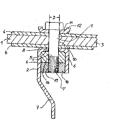
Fig. 2 is a cross-sectional view taken
along the line II-II in Fig. 1;
Fig. 3 shows a rubber cushion member for
the roller belt arrangement of
Fig. 1; and
- 2 -
,~, . . - ~ . : : .

2133376
Fig. 4 is a cross-sectional view of the
cushion member of Fig. 3 taken
along the line IV-IV thereof.
Summary of the Invention
The roller belt arrangement of the present
invention is characterized primarily in that that
end of the securing means that faces the driver or
gripper means is provided with an abutment member
for an elastomeric cushion member of rubber or
rubber-like material, with this cushion member
being supported against the cross-piece of the
base of the driver or gripper means. The cushion
member is preferably preloaded, which, if the
securing means is a screw bolt, can be -
accomplished by tightening the nut of the bolt or
by screwing the bolt into the abutment member.
The cushion member expediently has such a
dimension that in the installed state, it
partially fills the U-shaped base of the driver or
gripper means. Furthermore, the hole in the
crosspiece of the driver or gripper means for the~
securing means is preferably dimensioned in such
a way that it is slightly larger than the diameter
of the securing means.
The inventive cushion member leads to a non~
- 3 -

2~3337~ ~
rigid but rather resilient stresslng of the
securing means,-thereby protecting the securing
means from stress concentration and shearing
effects; in addition, the driver or gripper means
can also advantageously carry out a certain
deflection movement when it is stressed without
thereby losing its ability to provide traction.
The inventive cushion member is disposed
within the base of the driver or gripper means and
is therefore accommodated in a protected manner.
In order under these conditions to be able to
provide for an elastic deformability of the
elastomeric cushion member, for example the
preloading of the cushion member, the latter is
provided with recessed portions that become
smaller with the preload or other stressing action
or are filled in by the displaced or expanding
rubber.
It is furthermore also advantageous for the
inventive cushion member and the pertaining
abutment member at the end of the securing means~
to be dimensioned in such a way that both of these
members at least practically fill the U-shaped
base of the driver or gripper means.
The driver or gripper means is, in a known
- 4 -

~13337~
manner, embodied in such a way that one of the two
legs of the U-shaped base form the actual gripper
or driver portion, and in particular via an
appropriate extension or lengthening of that leg.
Further specific features of the present
invention will be described in detail
subsequently.
Description of Preferred Embodiments
Referring now to the drawing in detail, the
roller belt arrangement is essentially formed from
five (only three are illustrated) inextensible,
flexible, continuously rotating belts 1 that
extend parallel to one another. The belts are
guided on wheels of the vehicle and serve for the
mounting and securement of transversely disposed
driver or gripper means 2 that are intended to
ensure a positive drive in snow. The driver means
2 extend over the entire width of the roller belt
arrangement and span the gaps between the belts 1.
The belts 1 have an inextensible core 3 in
the form of superimposed rubberized fabric layers
as square-woven fabric. The top and bottom of the
core 3 is covered by a protective cover layer 4 of
rubber that is secured thereto.
The driver or gripper means 2 comprise a
- 5 -

2~33376~
steel section having a U-shaped base that serves
for anchoring the gripper means. The base has a
crosspiece 5 that extends parallel to the belt 1
and rests thereagainst, with legs 6 extending at
right angles from the crosspiece 5. One of the
legs 6 is extended to form the actual gripper or
driver portion 7. The crosspiece 5 has three
spaced-apart holes 8 for receiving screw bolts 9
that extend through a hole 10 in the belt 1 and on
the inner side of the belt 1 extend through a
metal strip 11 that has angled-off edges 12.
The free ends of the screw bolts 9 are
furthermore guided through holes 13 of a rubber
strip 14 and are screwed into threaded holes 15 of
a steel bar 16. The components 14, 16 have a
length that corresponds to the distance spanned by
the belts 1, and together fill the space between
the two legs 6 and the crosspiece 5 of the base of
the driver or gripper means 2. In addition, the
two sides of the rubber strip 14 are provided with
longitudinally extending notches or grooves 17.
These notches permit an elastic deformation as the
screw bolts 9 are screwed further and further into
the threaded holes 15 of the bar 16. This
deformation can be continued to such an extent

2133~7~
that the two notches 17 become smaller or, as
illustrated in Flg. 2, become completely filled in
due to the deforming or stretching rubber, with
there still being space for the deforming rubber
to spread at the end faces of the strip 14. :
By interposing a strip 14 between the end of
the screw bolt 9 with the bar 16 that serves as an
abutment on the one hand, and the crosspiece 5 on
the other hand, an elastic mounting of the driver
or gripper means 2 is provided, especially if the
back sides of the crosspieces 5 rest against the
protective rubber cover layer 4. An even more
advantageous mounting for avoiding breakage or
failure of the screw bolt 9 consists in making the
diameter of the hole 8 in the crosspiece 5 about
5-15~ greater than the diameter of the shaft of
the screw bolt 9. This diameter is indicated by
D in Fig. 2. With such a provision of the
diameters, the gripper or driver portions 7 can
carry out slight tilting movements relative to the
belts 1. These tilting movements are, however,~
elastically cushioned and limited by the strip 14.
In principle, it is also possible to utilize
for each bolt 9 a nut-like structure that extends
over the space between the two legs 6. However,
- 7 -

2~3~376
for reasons of stability and to contain the strip
14, it is more advantageous to use a bar 16 that
extends over the length of the strip 14, i.e. over
the overall width of the belts 1. It is also not
absolutely necessary to dispose the displacement
or spreading spaces in the form of notches 17 on
the outer sides of the strip 14; rather, such
displacement spaces can also be disposed on other
outer surfaces, or can even be hollow spaces.
lo The favorable effect resulting from the
inventive configuration can be attributed to the
fact that at the free end of the screw bolt 9, in
a direction toward the threaded holes 15, due to
the presence of the elastomer (the strip 14) from
a strength or stability and also resilience
standpoint, rather than an abrupt transition a
gradual transition results that to a large extent
precludes the aforementioned failure of the bolt.
With respect to such avoidance of bolt
failures, it is furthermore advantageous if the
transition "x" between the smooth, cylindrical,~
non-scored shaft of the bolt 9 and the portion 9'
that is provided with the thread be disposed in
the region of, i.e. at the level of, the strip 14.
In particular, as illustrated in Fig. 2, this
- 8 - ~ :

2~3337~
transition "x" should be disposed about half way :
through the cushion or strip 14.
The presen~ invention is, of course, in no
way restricted to the specific dlsclosure of the
specification and drawing, but also encompasses
any modifications within the scope of the appended
claims.
:. ,

Dessin représentatif
Une figure unique qui représente un dessin illustrant l'invention.
États administratifs

2024-08-01 : Dans le cadre de la transition vers les Brevets de nouvelle génération (BNG), la base de données sur les brevets canadiens (BDBC) contient désormais un Historique d'événement plus détaillé, qui reproduit le Journal des événements de notre nouvelle solution interne.

Veuillez noter que les événements débutant par « Inactive : » se réfèrent à des événements qui ne sont plus utilisés dans notre nouvelle solution interne.

Pour une meilleure compréhension de l'état de la demande ou brevet qui figure sur cette page, la rubrique Mise en garde , et les descriptions de Brevet , Historique d'événement , Taxes périodiques et Historique des paiements devraient être consultées.

Historique d'événement

Description Date
Inactive : CIB de MCD 2006-03-11
Demande non rétablie avant l'échéance 1999-09-30
Le délai pour l'annulation est expiré 1999-09-30
Réputée abandonnée - les conditions pour l'octroi - jugée non conforme 1999-02-04
Réputée abandonnée - omission de répondre à un avis sur les taxes pour le maintien en état 1998-09-30
Un avis d'acceptation est envoyé 1998-08-04
Lettre envoyée 1998-08-04
Inactive : Renseign. sur l'état - Complets dès date d'ent. journ. 1998-07-29
Inactive : Dem. traitée sur TS dès date d'ent. journal 1998-07-29
Inactive : Approuvée aux fins d'acceptation (AFA) 1998-06-09
Toutes les exigences pour l'examen - jugée conforme 1995-12-06
Exigences pour une requête d'examen - jugée conforme 1995-12-06
Demande publiée (accessible au public) 1995-04-02

Historique d'abandonnement

Date d'abandonnement Raison Date de rétablissement
1999-02-04
1998-09-30

Taxes périodiques

Le dernier paiement a été reçu le 1997-09-10

Avis : Si le paiement en totalité n'a pas été reçu au plus tard à la date indiquée, une taxe supplémentaire peut être imposée, soit une des taxes suivantes :

  • taxe de rétablissement ;
  • taxe pour paiement en souffrance ; ou
  • taxe additionnelle pour le renversement d'une péremption réputée.

Les taxes sur les brevets sont ajustées au 1er janvier de chaque année. Les montants ci-dessus sont les montants actuels s'ils sont reçus au plus tard le 31 décembre de l'année en cours.
Veuillez vous référer à la page web des taxes sur les brevets de l'OPIC pour voir tous les montants actuels des taxes.

Historique des taxes

Type de taxes Anniversaire Échéance Date payée
TM (demande, 3e anniv.) - petite 03 1997-09-30 1997-09-10
Titulaires au dossier

Les titulaires actuels et antérieures au dossier sont affichés en ordre alphabétique.

Titulaires actuels au dossier
ARNOLD JAGER
Titulaires antérieures au dossier
S.O.
Les propriétaires antérieurs qui ne figurent pas dans la liste des « Propriétaires au dossier » apparaîtront dans d'autres documents au dossier.
Documents

Pour visionner les fichiers sélectionnés, entrer le code reCAPTCHA :


Pour visualiser une image, cliquer sur un lien dans la colonne description du document. Pour télécharger l'image (les images), cliquer l'une ou plusieurs cases à cocher dans la première colonne et ensuite cliquer sur le bouton "Télécharger sélection en format PDF (archive Zip)" ou le bouton "Télécharger sélection (en un fichier PDF fusionné)".

Liste des documents de brevet publiés et non publiés sur la BDBC .

Si vous avez des difficultés à accéder au contenu, veuillez communiquer avec le Centre de services à la clientèle au 1-866-997-1936, ou envoyer un courriel au Centre de service à la clientèle de l'OPIC.


Description du
Document 
Date
(aaaa-mm-jj) 
Nombre de pages   Taille de l'image (Ko) 
Abrégé 1995-06-02 1 40
Revendications 1995-06-02 4 158
Dessins 1995-06-02 1 42
Description 1995-06-02 9 366
Revendications 1998-05-19 4 106
Dessin représentatif 1998-08-02 1 12
Avis du commissaire - Demande jugée acceptable 1998-08-03 1 166
Courtoisie - Lettre d'abandon (taxe de maintien en état) 1998-10-27 1 184
Courtoisie - Lettre d'abandon (AA) 1999-04-28 1 172
Taxes 1996-08-12 1 41
Demande de l'examinateur 1996-01-11 1 48
Demande de l'examinateur 1998-02-02 1 26
Correspondance reliée au PCT 1995-12-05 2 62
Correspondance de la poursuite 1997-09-29 1 29
Correspondance de la poursuite 1998-04-08 1 38