Sélection de la langue

Search

Sommaire du brevet 2133589 

Énoncé de désistement de responsabilité concernant l'information provenant de tiers

Une partie des informations de ce site Web a été fournie par des sources externes. Le gouvernement du Canada n'assume aucune responsabilité concernant la précision, l'actualité ou la fiabilité des informations fournies par les sources externes. Les utilisateurs qui désirent employer cette information devraient consulter directement la source des informations. Le contenu fourni par les sources externes n'est pas assujetti aux exigences sur les langues officielles, la protection des renseignements personnels et l'accessibilité.

Disponibilité de l'Abrégé et des Revendications

L'apparition de différences dans le texte et l'image des Revendications et de l'Abrégé dépend du moment auquel le document est publié. Les textes des Revendications et de l'Abrégé sont affichés :

  • lorsque la demande peut être examinée par le public;
  • lorsque le brevet est émis (délivrance).
(12) Demande de brevet: (11) CA 2133589
(54) Titre français: CYLINDRE ROTATIF DE VERROUILLAGE POUR SERRURE DE SURETE
(54) Titre anglais: ROTARY LOCKING CYLINDER FOR A SAFETY LOCK
Statut: Réputée abandonnée et au-delà du délai pour le rétablissement - en attente de la réponse à l’avis de communication rejetée
Données bibliographiques
(51) Classification internationale des brevets (CIB):
  • E05B 27/00 (2006.01)
  • E05B 19/00 (2006.01)
(72) Inventeurs :
  • KELLER, ERNST (Suisse)
(73) Titulaires :
  • ERNST KELLER
(71) Demandeurs :
  • ERNST KELLER (Suisse)
(74) Agent: NORTON ROSE FULBRIGHT CANADA LLP/S.E.N.C.R.L., S.R.L.
(74) Co-agent:
(45) Délivré:
(22) Date de dépôt: 1994-10-04
(41) Mise à la disponibilité du public: 1995-04-06
Requête d'examen: 2000-12-18
Licence disponible: S.O.
Cédé au domaine public: S.O.
(25) Langue des documents déposés: Anglais

Traité de coopération en matière de brevets (PCT): Non

(30) Données de priorité de la demande:
Numéro de la demande Pays / territoire Date
93 810 702.6 (Office Européen des Brevets (OEB)) 1993-10-05

Abrégés

Abrégé anglais


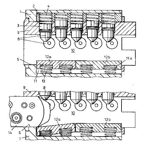
ABSTRACT OF THE DISCLOSURE
The rotary locking cylinder has a housing with a
longitudinal bore hole in which a rotor is inserted. In the lower
region of the bore hole, a groove-shaped recess is worked into the
housing, a blocking insert being inserted into this recess. This
blocking insert projects into the key groove and prevents the rotor
from being turned by force so as to shear off the tumbler pins.
When employing unauthorized opening methods, the blocking insert
must be held against the repelling force of spring elements in an
inactive position, which substantially impedes such unauthorized
methods or even renders them impossible.

Revendications

Note : Les revendications sont présentées dans la langue officielle dans laquelle elles ont été soumises.


The embodiments of the invention in which an exclusive property
or previlege is claimed are defined as follows:
1. In a rotary locking cylinder for a safety lock in
which spring-loaded pin tumblers are supported in bore holes
extending radially relative to a rotor and a cylinder housing and
can be brought into line by inserting a key into a key groove to
enable the rotation of the rotor, the improvement comprising: a
blocking insert which is supported in the housing and engages in
the key groove and is displaced outward against a repelling spring
force when the key is inserted in order to free the rotor for
rotation.
2. The rotary locking cylinder according to claim 1,
wherein the blocking insert is inserted into a recess of the
housing which is open at the rear.
3. The rotary locking cylinder according to claim 2,
wherein the recess extends substantially along the entire length of
the housing.
4. The rotary locking cylinder according to claim 1,
wherein said cylinder is of the double locking kind formed by two
individual cylinders connected by a connecting web.
5. The rotary locking cylinder according to claim 1,
wherein said blocking insert has a plurality of spring elements
which are arranged at a distance from one another in the recess and
supported at the housing.
6. The rotary locking cylinder according to claim 1,
wherein said blocking insert has at least two parts which are
movable outward independently from one another against a spring
force.
- 6 -

7. The rotary locking cylinder according to claim 2,
wherein said recess is wider than the key groove and said blocking
insert is slightly narrower than the key groove in an upper region
and slightly narrower than the recess in a lower region.
8. The rotary locking cylinder according to claim 6,
wherein each part is pressed against the rotor by means of at least
two spring elements which are arranged at a distance from one
another.
9. The rotary locking cylinder according to claim 6,
wherein said parts have bore holes on the underside, a spiral
spring supported at the housing engaging in these bore holes.
10. The rotary locking cylinder according to claim 6,
wherein said parts of the blocking insert are made of brass.
- 7 -

Description

Note : Les descriptions sont présentées dans la langue officielle dans laquelle elles ont été soumises.


~ 1 3 ~ J ~3 )
GK-ISL-645
ROTARY LOCKING CYLINDER FOR A SAF}STY LOCK
BACRGROUND OF THE INVENTION
a) Field of the Invention
The invention is directed to a rotary locking cylinder
and, in particular, to a rotary locking cylinder for a safety lock
in which spring-loaded pin tumblers are supported in bore holes
extending radially relative to a rotor and a cylinder housing and
can be brought into line by inserting a key into a key groove to
enable the rotation of the rotor.
b) Deccriptio~ of the Related Art
A rotary locking cylinder of this type is known, for
example, from EP-B-0 238 442. In break-in attempts, even high-
priced rotary locking cylinders of this kind are subject to a wide
variety of known and new methods of opening. Some of these methods
are non-destructive and incapable of detection. The rotary locking
cylinder according to the patent mentioned above foils such
methods, e.g. the vibration method, by way of a special a
construction of the tumblers. However, there are also methods of
unauthorized opening in which the rotary locking cylinder is
destroyed by the use of crude force. When attempting to open the
lock in this way, for example, rotation of the rotor is forced by
inserting a tool into the key groove so that the tumbler pins are
sheared off. This forced method of entry is difficult to combat by
modifying the rotary locking cylinder, since such changes are
restricted by preestablished dimensions. Yinally, such a rotary
locking cylinder should be simple and inexpensive to manufacture
and should operate reliably. A rotary locking cylinder which at
least substantially impedes a number of methods of unauthorized
opening at the same time would be particularly desirable.

'~133~8~
L~M~r OF THE PRESENT INVENTION
The invention therefore has the primary object of
providing a rotary locking cylinder of the type mentioned above
which offers better protection against at~empts at unauthorized
opening but is not substantially more expensive to produce. This
object is met by the invention wherein the improvement comprises a
blocking insert which is suppor~ed in the housing and engages in
the key groove and is displaced outward against a repelling spring
force when the key i5 inserted in order to free the rotor for
rotation.
In the rotary locking cylinder according to the invention
the above-mentioned break-in attempts are substantially impeded.
Forced turning of the rotor is impeded by increasing the shearing
cross section, i.e. the tailor-made tool employed for this purpose
must be inserted into the key groove along the entire length of the
latter. The tool which is inserted into the key groove strikes
against the core pins due to the spring pressure of the blocking
insert. These core pins are accordingly moved outward radially,
which results in a positive blocking by means of the core pins. It
is almost impossible to force a rotor which is blocked in this way.
In order to use the lock-picking method or vibration
method, the blocking insert would have to be held against the
spring pressure at the locking level along the entire length of the
key groove while attempting to open the lock. Accordingly,
additional manipulation is required so that the opening method is
made more difficult and the period of time required to successfully
open the lock is increased.
As will be seen, entirely different types of opening
methods are substantially impeded by the rotary locking cylinder
according to the invention.
The rotary locking cylinder can be operated in a
conventional manner with its accompanying key. When the key is
inserted into the key groove, the blocking insert is automatically
moved outward into an inactive position.
The rotary locking cylinder according to the invention
-- 2 --

~ 3 3 ~ 8 ~ :
can be manufactured in a partlcularly simple manner according to a
further development when the insert is inserted in a recess of the
housing which is open towar~ the rear. In this case, the insert
can be pushed into a longitudinal recess of the housing in the
manner of a slide or bolt. The ir~sertion of the blocking insert
may be effected during assembly of the rotary locking cylinder much
as the insertion of the housing pins. The insertion of the
blocking insert can accordingly be integrated very simply in a
known production process. This is an important feature in series-
manufactured products.
The locking security is considerably increased in a
further development of the invention in that the blocking insert
has a plurality of parts arranged one after the other which must be
displaced outward individually in order to release the rotor.
Accordingly, a plurality of parts of the blocking insert must be
brought into the inactive position simultaneously when unauthorized
opening is attempted.
The locking security is further increased in that the
blocking insert is held in the blocking position by means of at
least two spring elements which are arranged at a distance from one
another. Such a blocking insert is also still effective when
pressed outward at only one end. In this case, the blocking insert
is only inclined and the end which is not acted upon continues to
lock the rotor.
The rotary locking cylinder according to the invention
can also be a double locking cylinder having two individual parts
joined by a connecting web. In this case, the blocking inserts are
installed before connecting the individual cylinders. Accordingly,
the blocking inserts can also be pushed in from the rear in this
instance. Further advantageous features are contained in the
following claims and the description and drawing.
BRIEF DEBCRIPTION OF T~E DRAWINGS
In the drawings:
Fig. 1 shows a cross section through a rotary locking
-- 3

~ 3 ~` 8 ~
cylinder according to th~ invention; and
Figs. 2a to 2c show longitudinal sections through the
rotary locking cylinder with partial views of a key shaft.
D~SCRIPTION OF THE PREFERRED EMBODIMENT~
The rotary locking cylinder has a housing with a
' continuous bore hole 5 in which a rotor 9 is inserted. Spring-
loaded tumblers with springs 4, core pins 8 and housing pins 3 are
inserted into radial bore holes in the rotor 9 and into inserts 2
of the housing 1 in a known manner. A flat key or turn key 14 is
inserted into an open key groove 10 to enable rotation. If the
rotary locking cylinder has two individual cylinders, these
cylinders are connected with one another by a web 7 inserted into
the cylinder pocket 6. The rotary locking cylinder according to
the invention can be a single rotary locking cylinder or double
rotary locking cylinder.
A recess 11 extending in the longitudinal direction of
the rotary locking cylinder is worked into the housing 1 in the
lower region of the bore hole 5. As will be seen from Fig. 2a,
this recess is open at the rear, i.e. with reference to the figure,
while it is closed in the front. A blocking insert 12 having two
parts 12a and 12b which are T-shaped in cross section and made of
brass, for example, is inserted into this groove-shaped recess 11.
The parts 12a and 12b have two pocket bore holes 12c in the
underside, spiral springs 13 being inserted into the latter. The
spiral springs 13 supported at the housing 1 hold parts 12a and 12b
in the position shown in Figures 1 and 2a. Since, as can be seen
in the drawing, parts 12a and 12b project into the key groove 10
which is open at the bottom, the blocking insert 12 connects the
rotor with the housing 1 in the position shown in the drawing.
Accordingly, the rotor could not be turned even when the tumblers
are brought into line. Consequently, a lock with this rotary
locking cylinder could not be opened by a break-in method in which
the tumblers are simply brought into line.
_ ~, _

f~
The rotary locking cylinder can be operated i~ a
conventional manner by inserting the correct turning key 14 into
the key groove 10 as is shown in Figures 2b and 2c. When the key
14 is inserted into the key groove 10 from the front, as is shown
in Fig. 2, part 12a first and then part 12b are moved downward into
the recess 11 against the repelling force of the springs 13. In
the position shown in Fig. 2c in which the key 14 is completely
inserted into the key groove 10, parts 12a and 12b no longer
project beyond the recess 11 at the top and also no longer engage
in the key groove 1o. Since the tumblers are simultaneously
brought into line by the key 14, the rotor 9 is released.
Parts 12a and 12b have a T-shaped cross section, as is
shown in Fig. 1, along their entire length. Accordingly, they have
an upper projection 12c which is only slightly narrower than the
key groove 10. A lower region 12e is wider than the key groove 10
and only slightly narrower than the recess 11. The wider region
12e accordingly forms a stop which prevents parts 12a and 12b from
being pressed completely into the key groove 10 by the springs 13.
When the key 14 is removed, parts 12a and 12b immediately move
automatically into the position shown in Fig. 2a.
While the foregoing description and drawings represent
the preferred embodiments of the present invention, it will be
obvious to those skilled in the art that various changes and
modifications may be made therein without departing from the true
spirit and scope of the present invention.

Dessin représentatif
Une figure unique qui représente un dessin illustrant l'invention.
États administratifs

2024-08-01 : Dans le cadre de la transition vers les Brevets de nouvelle génération (BNG), la base de données sur les brevets canadiens (BDBC) contient désormais un Historique d'événement plus détaillé, qui reproduit le Journal des événements de notre nouvelle solution interne.

Veuillez noter que les événements débutant par « Inactive : » se réfèrent à des événements qui ne sont plus utilisés dans notre nouvelle solution interne.

Pour une meilleure compréhension de l'état de la demande ou brevet qui figure sur cette page, la rubrique Mise en garde , et les descriptions de Brevet , Historique d'événement , Taxes périodiques et Historique des paiements devraient être consultées.

Historique d'événement

Description Date
Inactive : CIB de MCD 2006-03-11
Demande non rétablie avant l'échéance 2003-10-06
Le délai pour l'annulation est expiré 2003-10-06
Réputée abandonnée - omission de répondre à un avis sur les taxes pour le maintien en état 2002-10-04
Lettre envoyée 2001-01-23
Inactive : Renseign. sur l'état - Complets dès date d'ent. journ. 2001-01-22
Inactive : Dem. traitée sur TS dès date d'ent. journal 2001-01-22
Exigences pour une requête d'examen - jugée conforme 2000-12-18
Toutes les exigences pour l'examen - jugée conforme 2000-12-18
Demande publiée (accessible au public) 1995-04-06

Historique d'abandonnement

Date d'abandonnement Raison Date de rétablissement
2002-10-04

Taxes périodiques

Le dernier paiement a été reçu le 2001-08-20

Avis : Si le paiement en totalité n'a pas été reçu au plus tard à la date indiquée, une taxe supplémentaire peut être imposée, soit une des taxes suivantes :

  • taxe de rétablissement ;
  • taxe pour paiement en souffrance ; ou
  • taxe additionnelle pour le renversement d'une péremption réputée.

Veuillez vous référer à la page web des taxes sur les brevets de l'OPIC pour voir tous les montants actuels des taxes.

Historique des taxes

Type de taxes Anniversaire Échéance Date payée
TM (demande, 3e anniv.) - petite 03 1997-10-06 1997-09-16
TM (demande, 4e anniv.) - petite 04 1998-10-05 1998-09-21
TM (demande, 5e anniv.) - petite 05 1999-10-04 1999-09-20
TM (demande, 6e anniv.) - petite 06 2000-10-04 2000-09-07
Requête d'examen - petite 2000-12-18
TM (demande, 7e anniv.) - petite 07 2001-10-04 2001-08-20
Titulaires au dossier

Les titulaires actuels et antérieures au dossier sont affichés en ordre alphabétique.

Titulaires actuels au dossier
ERNST KELLER
Titulaires antérieures au dossier
S.O.
Les propriétaires antérieurs qui ne figurent pas dans la liste des « Propriétaires au dossier » apparaîtront dans d'autres documents au dossier.
Documents

Pour visionner les fichiers sélectionnés, entrer le code reCAPTCHA :


Pour visualiser une image, cliquer sur un lien dans la colonne description du document. Pour télécharger l'image (les images), cliquer l'une ou plusieurs cases à cocher dans la première colonne et ensuite cliquer sur le bouton "Télécharger sélection en format PDF (archive Zip)" ou le bouton "Télécharger sélection (en un fichier PDF fusionné)".

Liste des documents de brevet publiés et non publiés sur la BDBC .

Si vous avez des difficultés à accéder au contenu, veuillez communiquer avec le Centre de services à la clientèle au 1-866-997-1936, ou envoyer un courriel au Centre de service à la clientèle de l'OPIC.


Description du
Document 
Date
(aaaa-mm-jj) 
Nombre de pages   Taille de l'image (Ko) 
Dessin représentatif 1998-03-05 1 40
Page couverture 1995-06-03 1 55
Dessins 1995-06-03 2 110
Abrégé 1995-06-03 1 33
Revendications 1995-06-03 2 86
Description 1995-06-03 5 300
Accusé de réception de la requête d'examen 2001-01-23 1 180
Courtoisie - Lettre d'abandon (taxe de maintien en état) 2002-11-04 1 179
Correspondance 1994-11-25 2 89
Taxes 1996-09-12 1 58