Note : Les descriptions sont présentées dans la langue officielle dans laquelle elles ont été soumises.
~ ~ ~ 3 ~ ~ 3 ~
-
BEMOTE MOTO~ SWITCH ARD CAPACITOR ASSEMBLY
FIELD OF T~E IRVERTIO~
This invention relates to electrical motors. More
specifically, it relates to industrial electric fanc and fan
controls.
BA~KOUI~D OF THE IRVE~TIOJ
Industrial electric fans may include a motor casing
enclosed at one end by a removable modular end dome. Generally,
the end dome has mounted thereto a power cord, a motor switch
and a motor capacitor. An example of a present day electrical
fan motor modular end dome is disclosed in U.S. Patent No.
4,517,481.
Two of the most frequently serviced components in an
industrial fan are the switch and the motor capacitor.
Replacing these components is facilitated by placing them
together in a removable modular end dome. However, replacement
of either the switch or the capacitor in present day fans is
still very time consuming and consequently very expensive. A
technician must first access the modular end dome. This may
require the assembly of scaffolding or the use of an alternative
lifting device for the technician to reach the fan. Once the
technician has accessed the fan he must use tools to remove the
end dome, and then reassemble the fan with a new end dome. In
many circumstances, it may be necessary to wait until there is a
lull in manufacturing activity to permit the technician to
access the fan. This concern has been partially addressed by
the fan motor switch disclosed in U.S. Patent No. 5,130,587
- 2 - 2~3~3~
whlch dlscloses a drop cord wlth a two-speed electrlc motor
swltch at the end of the drop cord remote from the modular end
dome.
SUMMARY OF THB INVBNTION
The present lnventlon provldes an electrlc fan motor
comprlslng a motor caslngJ a motor fleld coll dlspo~ed ln the
caslng; a power cord extendlng from the caslng; a remote hand
~et lncludlng a swltch and a motor capacltor dlsposed ln a
swltch/capacltor box and electrlcally connected to the motor
fleld coll by a control cord wlth a selectlvely engageable plug
whereln complete electrlcal servlclng of the swltch and
capacltor ls executed by unplugglng the hand set and replaclng
lt wlth a functlonlng hand set.
The present lnventlon provldes a remote hand set whlch
completely replaces the removable modular end dome. the remote
hand set enables a technlclan to slmultaneously replace both the
swltch and the motor capacltor ln less than a mlnute wlthout the
need to access the fan motor. Thls greatly reduces the cost of
malntalnlng electrlc fan motors. The remote hand set lncludes
a swltch/capacltor box havlng both the swltch and the motor
capacltor dlsposed thereln. An electrlcal control cord wlth a
selectlvely engageable plug ls dlsposed between the motor
ca~lng and the swltch/capacltor box. The control cord
electrlcally connects the capacltor and the swltch wlth the
motor fleld coll. The swltch and capacltor are easlly replaced
by a technlclan by merely dlsconnectlng the ~wltch/capacltor
6 . . ~
- 2a - ~ ~3 ~3 ~
box from the motor at the plug and substltutlng a new swltch/
capacltor box. The ellmlnatlon of the modular end dome has the
secondary effect of ellmlnatlng the need for components
assoclated wlth the end dome such as an electrlcal connector
between the end dome and the motor caslng and bracketry and
fasteners for mountlng the capacltor ln the modular end dome as
well as fasteners attachlng the end dome to the motor caslng.
Thls lnventlon has the further advantage of provldlng an
electrlc fan motor made smaller ln slze wlth the ellmlnatlon of
the modular end dome. Smaller fan motors are advantageous
because they reduce the amount of warehouse space needed for
storing a glven quantlty of fans, and also reduce the cost of
packaglng and shlpplng fans.
-3~
~IEF DESCaIPTIO~ OF T~ DBA~I~ES
Flgure 1 is a diagrammatlc representation of a fan
motor casing and a connecting remote hand set.
F~8ure 2 i8 a schematlc representation of the
electrical connections between the remote hand set and the fan
motor casing.
Figure 3 is a side view of a two speed swltch.
D~SC~IPTIO~ OF 1~ u BMBODI~R~IS
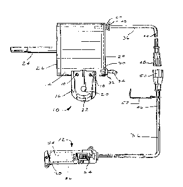
Figure 1 shows an electric fan motor 10 having a
remote hand set 12. A motor casing 14 has a motor field coil
disposed therein. The motor casing 14 is pro~ided with a pair
of mounting brackets 16, each welded to the motor casing 14 at
two points 18. The mounting bracket 16 i9 provided with a plvot
pin hole 20 for receiving a suitable pivot pin, not shown, for
mounting the fan motor upon a supporting bracket, not ~hown,
whlch may be attached to a wall surface, a floor stand,
structural steel or other conventional fan support structure.
The bracket 16 also includes an ad3ustment screw receiving slot
22 for locking the angular position of the fan motor 10 on its
supportlng structure. A drive shaft 24 rotatably connected wlth
the motor field coil extends from a front end 26 of the casing
14. This configuration is very similar to that shown in U.S.
Patent No. 5,130,587 issued to Janisse et al on July 14, 1992.
In accordance with the invention, a rear end 28 of
the motor casing 14 has a flat or plate shape. The rear end 28
of the motor casing 14 is prorided with a flrst HEYCO fltting
hole 30. Alternatively, the hole 30 could be placed in a side
of the casing prosimate to the rear end 28. Operatively mounted
~13~
ln the HEYCO fitting hole 30 i9 a HEYCO fitting or strain relief
connection member 32 on one end of a conventional power cord
34. HEYCO fittings are 9tandard or conventional strain relief
fittings, and they are available from HEYCO MOLDED PRODUCTS,
INC., Box 160, Kenilworth, New Jersey 07033, under Model No. 6N
3-4. The power cord has formed on the other end thereof, a male
connector member, not shown, and a connector clamp, not shown,
for securing the power cord to a suitable power extension cord
in turn connected to a power source. It i9 al90 contemplated,
in an alternative embodiment, that power cord 34 enter directy
into hand set 12 from a source of power. The power could then
be delivered to motor 10 by way of conductors located within
cord 36 (such conductor not shown).
The remote hand set 12 i9 connected to the rear 28 of
the motor casing 14. Other connecting sites on the motor casing
14, such as a side proximate to the rear end 28 may be
alternatively used. A switch/capacitor control cord 36 of the
hand set 12 connects a switch/capacitor box 38 with the motor
casing 14. A second HEYCO fitting hole 40 is disposed in the
rear 28 of the motor casing 14. Again, other locations on the
casing 14 may also be appropriate connecting 9ite9. Operatively
mounted in the second fitting hole 40 by means of a HEYCO
fitting or strain relief connection member 42 is the control
cord 36. The control cord 36 has a first part 44 and a second
part 46. The first part 44 extends from the HEYCO fitting 42 at
the rear 28 of the casing 14 to a female connector 48 adapted to
be received by a male connector 50 which is one end of the
second part 46 of the control cord 36. The second part 46 of
the control cord 36 extends from the male connector 50 into the
switch/capacitor box 38. Both the first part and the second
part 44, 46 are fairly short. The second part 46 is only about
one foot long, permitting an operator or technician to reach the
engaged control cable connectors 48, 50 without the aid of a
ladder or hoist. One or more extension cords, not shown, with
3 ~
--5--
clamp members 52 are used when the distance between the fan
motor 10 and the operator become too great for the first and
second parts 44, 46 of the control cord 36.
The switch/capacitor box 38 has mounted therein a
two-speed switch 54 and a conventional motor capacitor 56. A
suitable two-speed switch 54 is illustrated in Figure 3. The
preferred switch is known as a McGill rocker switch Model No.
0805-1253, and i~ available from the McGill Switch Company, a
division of the McGill Manufacturing Company, Inc. of
Valparaiso, Indiana 46383. The switch 54 has three positions,
namely a low speed position, a high speed position and an off
position.
The motor capacitor 56 i8 rectangular in shape and is
preferably mounted in a separate compartment 58 in the
switch/capacitor box 38 proximate to the switch 54. The
separate compartment guards against damage due to leakage of the
capacitor 56. Electrical conductors in the control cord 36,
schematically represented in Figure 2, electrically connect the
switch 54 and the capacitor 56 (in the switch/capacitor box 38)
with the motor field coil and power cord 34.
Electrical conductors have been marked with the usual
color scheme for cooperation with the mating color coded
electrical conductors in the power cord 34, the switch/capacitor
control cord 36 and the McGill switch 54. The color codes for
the prongs on the McGill switch are labeled in Figure 3 and they
match the same color code~ for the electrical conductors shown
in Figure 2. The electrical conductors returning from the
switch/capacitor box 38 are connected to the appropriate
electrical components within the motor casing 14 thereby
electrically connecting the components in the switch/capacitor
box 38 with the motor field coil.
~ ~3~
--6--
A significant advantage of an electrical fan motor 10
equipped with the remote hand 9et 12 of the present invention is
readily apparent when there is a need to service the fan motor
10. Failure of the switch 54 and failure of the motor capacitor
56 are typically the two leading repair items on industrial
electrical fan motors 10. Removing and replacing switches 54
and capacitors 56 mounted in a modular end dome as described in
U.S. Patent No. 5,130,587 is often inconvenient because of the
inaccessible location of the fan motor 10 and the need for tools
in removing and installing the end dome.
The present invention greatly facilitates removal and
replacement of both the switch 54 and the capacitor 56. A
service technician can quickly repair most fan problems by
simply removing the remote hand set 12 by unplugging the
connectors 48 and 50 by reaching no higher than his head. A
functional hand set 12 is then plugged in and the clamp member
52 replaced to put the fan motor 10 back in operation. The
entire procedure requires no tools and approximately ten seconds
to execute. The defective hand set 12 is then returned to a
maintenance area for replacement of the defective part. The
rebuilt hand set 12 is then placed in stock to be used as a
future replacement.
It is appreciated that this preferred embodiment does
not illustrate the entire scope of the invention. Differing fan
applications may result in varying embodiments. It may be
advantageous in some circumstances to have the power cord
connect to the switch/capacitor box instead of to the motor
casing.