Sélection de la langue

Search

Sommaire du brevet 2133953 

Énoncé de désistement de responsabilité concernant l'information provenant de tiers

Une partie des informations de ce site Web a été fournie par des sources externes. Le gouvernement du Canada n'assume aucune responsabilité concernant la précision, l'actualité ou la fiabilité des informations fournies par les sources externes. Les utilisateurs qui désirent employer cette information devraient consulter directement la source des informations. Le contenu fourni par les sources externes n'est pas assujetti aux exigences sur les langues officielles, la protection des renseignements personnels et l'accessibilité.

Disponibilité de l'Abrégé et des Revendications

L'apparition de différences dans le texte et l'image des Revendications et de l'Abrégé dépend du moment auquel le document est publié. Les textes des Revendications et de l'Abrégé sont affichés :

  • lorsque la demande peut être examinée par le public;
  • lorsque le brevet est émis (délivrance).
(12) Demande de brevet: (11) CA 2133953
(54) Titre français: MACHINE A TRANCHER LA VIANDE, ET SA METHODE D'UTILISATION
(54) Titre anglais: MEAT SLICING MACHINE AND METHOD OF USE THEREOF
Statut: Réputée abandonnée et au-delà du délai pour le rétablissement - en attente de la réponse à l’avis de communication rejetée
Données bibliographiques
(51) Classification internationale des brevets (CIB):
  • B26D 07/30 (2006.01)
  • B26D 07/18 (2006.01)
(72) Inventeurs :
  • CAREY, JOSEPH (Irlande)
(73) Titulaires :
  • TOWNSEND ENGINEERING COMPANY
(71) Demandeurs :
  • TOWNSEND ENGINEERING COMPANY (Etats-Unis d'Amérique)
(74) Agent:
(74) Co-agent:
(45) Délivré:
(86) Date de dépôt PCT: 1993-04-16
(87) Mise à la disponibilité du public: 1993-11-11
Requête d'examen: 1995-03-17
Licence disponible: S.O.
Cédé au domaine public: S.O.
(25) Langue des documents déposés: Anglais

Traité de coopération en matière de brevets (PCT): Oui
(86) Numéro de la demande PCT: PCT/US1993/003649
(87) Numéro de publication internationale PCT: US1993003649
(85) Entrée nationale: 1994-10-20

(30) Données de priorité de la demande:
Numéro de la demande Pays / territoire Date
921303 (Irlande) 1992-04-23

Abrégés

Abrégé anglais

2133953 9322114 PCTABS00027
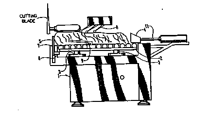
A meat slicing machine has a frame (1) and a meat supporting bed
(2) having a load cells (3) associated with supporting bed (2)
for weighing the meat product on the bed. Gripper claws of a
gripper box (4) are adapted to grip the meat product. A pressure plate
(5) having a limit switch (6) is adapted to be engaged by the
meat product. A shear-edge (7) is provided on frame (1) as the meat
product passes under measuring lasers (8). A profile finger (9)
measures the width of the meat product. Lasers (8) or
potientometers (10) measure the height of the product. The lead screw (11)
pushes the meat product towards the pressure plate (5) to measure
the length of the product. The method involves weighing the meat
product, measuring the height, length and width of the meat
product; determining the volume and density of the meat product; and
slicing a portion of the meat product having a predetermined weight
into a plurality of slices having a uniform thickness.

Revendications

Note : Les revendications sont présentées dans la langue officielle dans laquelle elles ont été soumises.


The embodiments of the invention in which an exclusive
property or privilege is claimed are defined as follows:
1.
The method of slicing a plurality of drafts from an
elongated slab of meat product, comprising,
laying a slab of product to be sliced on a supporting surface
located upstream from a slicing blade wherein said slab
has forward and rearward ends, opposite sides, and upper
and lower surfaces,
weighing said slab and measuring the length thereof while said
slab is on said supporting surface,
comparing the weight and length of said slab with historical
data of known historical slabs having similar weights,
lengths and density factors, and selecting an operational
density factor from said historical data based upon
historical slabs having weights and lengths similar to
that of said slab,
selecting a predetermined draft weight,
selecting a predetermined number of slices for each draft to
be sliced,
calculating the volume of a first draft of said slab having
said predetermined draft weight, and
slicing said first draft into said predetermined number of
slices of equal thickness.

2.
The method of claim 1 comprising the further step of
selecting predetermined parameters for the thickness of each
slice and slicing said first draft within said parameters.
3.
The method of claim 1 wherein said slab is held against
movement while its length and weight are being measured.
4.
The method of claim 1 wherein the upper and lower ends of
said slab are held against relative movement as said slab is
moved towards said slicing blade to prevent reactive movement
of said slab while it is being sliced.
5.
The method of claim 1 wherein the steps therein are re-
peated for a plurality of drafts until the length of said slab
is sliced, and wherein the thickness of the slices of each
draft vary from draft to draft in direct relation to the
variances in thickness of each draft.
6.
The method of claim 5 wherein the thickness of each slice
falls within predetermined thickness parameters selected prior
to the commencement of slicing any of said slab.

7.
The method of claim 1 wherein the volume of said first
draft is determined in part by measuring its lateral width and
by sensing the configuration of its upper surface to determine
an average face area.
8.
The method of claim 7 wherein the configuration of the
upper surface of said slab and the drafts of said slab are
sensed by a sensor means that is free from physical contact
with said slab.
9.
The method of claim 8 wherein said sensor means is a
laser means.
10.
The method of claim 4 wherein vertical pressure is ex-
erted on said first draft as it is moved towards said slicing
blade.
11.
The method of claim 1 wherein said slab is grasped at its
upper and lower ends by upper and lower transport elements,
respectively, to move said slab towards said slicing blade,
and equalizing the speed of travel of said transport elements
to maintain said slab in a relatively flat and stable position
as said plurality of drafts are being sliced.

12.
The method of claim 1 wherein vertical pressure is ex-
erted on each draft to be sliced as said slab moves toward
said slicing blade.
13.
The method of claim 1 wherein the thickness of each slice
is determined by controlling the velocity of said slab towards
said slicing blade.
14.
The method of claim 13 wherein the thickness of the
slices in said first draft with respect to slices in a sub-
sequent draft to be sliced is varied by changing the velocity
of said slab towards said slicing blade during the times when
said first draft and said subsequent draft is being sliced.
15.
The method of claim 1 wherein the actual density of said
slab is calculated after it is sliced, and said actual density
along with the actual weight and length of said slab is
recorded and stored for subsequent use in conjunction with
said historical data.
16.
A machine for slicing an elongated slab of meat product
into a plurality of drafts of substantial equal predetermined
weights and the same predetermined number of slices with the
slices in each draft having the same thickness, comprising,

a frame having an inclined support surface with upper and
lower ends,
a slicing means on said frame adjacent the lower end of said
support surfaces,
first means on said frame for weighing an elongated slab on
said support surface,
second means on said frame for measuring the length thereof
before said slab is sliced, whereupon the length and
weight of said slab can be measured while said slab is on
said supporting surface to permit comparison thereof with
historical data of known historical slabs having similar
weights, lengths and density factors.
17.
The machine of claim 16 wherein means are provided on
said frame for moving a slab of meat towards said slicing
means on said support surface and to a length measuring
position upstream from said slicing means; stop means on said
frame for stopping said slab of meat at said length measuring
position, and means on said frame for measuring the lateral
width and upper surface of said slab of meat as it moves from
said position towards said slicing means.
18.
The machine of claim 16 wherein a computer means are
operatively connected to said first and second means, said
computer means having a storage bank therein including known

historical data on slabs of meat having known weights,
lengths, and density factors, means on said computer means for
comparing the weight and length of said slab to said
historical data for comparison with historical slabs of
similar weight and length to permit identification of the
density factor of such historical slabs.
19.
The machine of claim 17 wherein said means for measuring
the upper surface of said slab is free from physical contact
with said slab.
20.
The machine of claim 19 wherein said means for measuring
the upper surface of said slab is a laser means.
21.
The machine of claim 17 wherein a gripper means on said
frame moves said meat slab to said length measuring position,
said gripper means having a plurality of gripper elements
thereon, said gripper means and said gripper elements being
operationally connected to a control means so that said
gripper elements will physically grip an upper end of said
slab when said slab is in said length measuring position.
22.
The machine of claim 21 wherein second gripping elements
are mounted on said frame downstream from said stop means to

grip the lower end of said slab as it moves toward said
slicing means.
23.
The machine of claim 22 wherein said gripper means and
said second gripping elements are interconnected to move both
the upper and lower ends of said slab towards said slicing
means at the same velocity, and to hold said slab in a stable
and flat position on said support means as it moves toward
said slicing means.
24.
The machine of claim 23 wherein a holddown roller on said
frame engages the upper surface of said meat slab downstream
of said stop means.
25.
The machine of claim 17 wherein said stop means is a
pivotal gate.
26.
The machine of claim 17 wherein means are on said frame
for measuring the lateral width and upper surface of said slab
of meat as it moves from said length measuring position
towards said slicing means; said computer means being
operationally connected to said means for measuring the
lateral width and upper surface of said slab of meat, means on
said computer for receiving the weight of drafts of said meat
slab to be sliced and the number of slices per draft, means on

said computer to determine the volume and density of a first
draft to be sliced using said identified density factor, speed
control means in said computer means to move said slab of meat
and said first draft towards said slicing means, said speed
control means operationally connected to said computer so that
said first draft will be advanced towards said slicing means
at a constant speed that will create a first draft at said
predetermined weight with said predetermined number of slices
all of uniform thickness.
27.
A machine for slicing an elongated slab of meat product
into a plurality of drafts of substantial equal predetermined
weights and the same predetermined number of slices with the
slices in each draft having the same thickness, comprising,
a frame having an inclined support surface with upper and
lower ends,
a slicing means on said frame adjacent the lower end of said
support surfaces,
first means on said frame for weighing an elongated slab on
said support surface,
second means on said frame for measuring the length thereof
before said slab is sliced,
a computer means operatively connected to said first and
second means,

said computer means having a storage bank therein including
known historical data on slabs of meat having known
weights, lengths, and density factors, means on said
computer means for comparing the weight and length of
said slab to said historical data for comparison with
historical slabs of similar weight and length to permit
identification of the density factor of such historical
slabs.
28.
The machine of claim 27 wherein means are on said frame
for measuring the lateral width and upper surface of said slab
of meat as it moves from a length measuring position upstream
from said slicing means towards said slicing means; said
computer means being operationally connected to said means for
measuring the lateral width and upper surface of said slab of
meat, means on said computer for receiving the weight of
drafts of said meat slab to be sliced and the number of slices
per draft, means on said computer to determine the volume and
density of a first draft to be sliced using said identified
density factor, speed control means in said computer means to
move said slab of meat and said first draft towards said
slicing means, said speed control means operationally
connected to said computer so that said first draft will be
advanced towards said slicing means at a constant speed that

will create a first draft at said predetermined weight with
said predetermined number of slices all of uniform thickness.

Description

Note : Les descriptions sont présentées dans la langue officielle dans laquelle elles ont été soumises.

~ ) 2133953 ~c~f
Title: ME~r SI,ICING M~CEIIN~ AND METHO~ OF I~SE: THER~OF.
My in~ention relate6 t~ a me~t slicil~g ~achine ~nd ~thod
of u~e thereof~ and more particularly, to 2 maahine to aLice
bacon ~nd the like.
Slicing mechine6 o~ the prior ~rt compri~e 8 rotating
blad~ ~hich either ha~ a ~piral cutting edge or ~ circul~r
cutting edge and iB mounted for planetary ~otion, ~nd me~ne to
feed the product toward~ ~he blade so that ~pon each
revolu~ion or each gyration of the bl~de, one ellce i6 cut
from the f~ce of the produ~. 'rhe ~eans to feed the product
may be a continuou~ conveyor but usu~l1y the ~lice include~
f ixed platf orm on which th~: product i8 plac~d ~nd a f Reding
head which engages thel rear f~ce of the product and which
urge~ it towards the blade. The fe~dlng head i8 moved by a
timing belt or by a le~d screw dri~ren by ~ ~tepp~ ng or
varl-~ble epeed electric motor .
Meat s1icing machine6 have a cv~on App1ic~tion in the
me~lt indu6try. 'rhey ~erve to slice raw/cooked m~a'c producte
li~ce beef ~ bacon and ham, etc., into con6usner u~ble po~tione1,.
The5e portion~ may be ~elected by weight, ~ize or nuniber of
slice6. The trend today and indeed the de~and is for fixed
weight portion~ with a fixed number o~ s1ices per p~ck and at
~ fixed price. See doCUments US-A 5,111,717, US-A ~,527,0~8,
FR-A 2,627~423, ~B-A 2,0~9,609 ~nd GB-A 591,912.
The present s1icin~ machines whi16t very expen~ive
fail to achiev~ fully the per~ormance demanded by the
meat indu~try . This i~ p~rticularly

~093r22l~4 2 1 3 3 9 5 3 PcT/US93/O~9
true in t~e bacon processin~ industry where the
endeavour is to produce packs of sliced rashers of
even slice thickness to a fixed target weight. The
present slicing machines~ failure is due mainly in
part to the varying dimensions/density factors that
the raw material presents.
Nore recently, slicing machines have been made
more sophisticated by the inclusion downstream of the
slicing machine of means to weigh a group of slices
cut by the slicing machine, and then, in dependence
upon the weight of this preceding~group, vary the
speed of movement of the product towards the blade by
a feedback system to insure, as far as possible that
each slice has a particular, predetermined weight.
This apparatus is very complicated, and inevitably,
there is some time lag between the cutting of a group
of slices and the determination that the group has
been cut too thickly or too thinly.
Further developments made use of the dif~erences
between pieces of meat products by weighing the piece
and measuring its length to achieve its Hweight per
unit length.~ Further use hàs been made of the well-
known fact that meat products have a ~weight
distribution curve~ particular to the individual type
of product.
Computer programs have been used to utilize such
gathered information so as to produce ~an anticipated
weight distribution~ for a particular product to be
sliced, and to target a desired individual ~slice
weight.~ This is repeated until the required number
of slices for the package weight`is found. This
system produces reasonable results but fails tQ
produce a pack with uniform slice thicknesses within
.

~093/22114 2 1 3 3 g S 3 PCT/US93/03~9
-- 3 --
the package, and this is due to the fact that the
system is designed to produce an individual slice
weight ~y varying the individual slice thicknesses to
accomplish this result.
A further disadvantage of the above system is the
means to weigh the product. The operator is required
to first place the meat on the platter (weighing
scale) to register the weight, and then remove it and
place it on the slicer table. This obviously entails
double handling of the product. It is, thereforer an
object of this invention to adapt a system and method
of slicing meat which can be applied to existing
conventional meat slicing equipment.
A further ob~ect of this invention is to provide
a method and means for handling the variable factors
of a given meat product relating to dimensions and
density 80 as to satisfy the performance demands for
fixed weight packages with a uniform slice thickness
throughout the pack.;
BRIEF DESCRIPTION OF THE DRAWINGS
Figure l is a graphic representation of a side of
bacon and the equation and means for approximating its
area; and
~ Figure 2 is a side elevation of the machine for
- measuring the physical dimensions, i.e., weight,
length, depth and width of the product to be sliced.
,
DISCLOSURE OF THE INVENTION
qith reference to Figure 2, a meat slicer (l) has
a roller-bed (2) which rests on a weight load cell
; (3). The weight of the meat product is recorded when
it is placed onto roller-bed (2). Gripper-box (4)

1093/22tl4 2 1 3 3 9 5 3 PCT/US93/03649
pushes the product along the roller-bed (2) until it
is up against pressure plate (5) where a limit switch
(6) is activated and the feeding operation stops. At
this point, the length of the product is measured, and
the gripper claws of gripper-box (4) grips the
product.
The product moves forward to the shear-edge (7)
having passed under the profile measuring lasers (8).
The laser heads measure the varying contours on the
top of the product while the side profile finger (g)
(potentiometer) measures the width.
With reference to Figure 1, the face area of the
product is ca}culated by means of lasers or potenti-
ometers (10). With this information, a selected
volume which is representative of the required portion
can be determined, which in turn will be a draft
thickness that is divided into the required number of
slices (i.e., rashers of uniform thickness)~
According to this invention, the operator places
the product to be sliced on the slicer roller-bed (2).
As can be seen in Figure 2, the roller-bed forms part
of the weighing system comprised of load cells (3).
On pressing the start button of the machine, the
weight of the product is recorded. The product now
moves forward by a lead screw (11) until it is pushed
up against the pressure plate (5), hence the feed
process stops, and at this point, the length, height
and width are recorded to achieve an estimated volume
for that particular piece, and hence its estimated
density. An encoder is linked to the lead screw (11)
to measure the travel of the lead screw. This permits
the determination of the length of the product. The
lead screw stops, as indicated above, when the product

-b 93/22114 r 2 1 3 3 9 5 3 PCT/US93/0 ~ 9 i;
is pressed against the pressure plate (5) where a
limit switch (6) is activated. The height across the
face of the product is measured by lasers (8~, and the
width measurement is recorded by the s~de flnger (9)
(potentiometer) as also discussed here before. From
these physical dimensions, it is possible to ascertain
the face area of the product and use the estimated
density as a correction factor. It is thereupon
possible to find the required volume of product
representative of the required package weight. This
calculated overall thickness is then divided by the
required number of slices for the package. For a 200
gm. package, assuming a denslty of 1, a preferred
volume requirement would be 200 cubic cm. This is
achieved by moving the product forward through the
slicer blade at fixed speed for that individual
package, thus insuring a slice of uniform thickness
for each revolution of the blade.
The slicing machine also includes a standard ~off
the shelf~ ty~e compute~ (~C). This computer can be
programmed to hold up to 99 product data files. A
product file will hold such information as: Product
Type, Package Weight, Number of Slicec, Slice
Thickness Parameters, etc. The computer is also
programmed to hold the individual parameters of each
piece of product placed on the slicer bed, and this
forms part of the management system for statistical
analysis.
A further very important use of the stored
~nformation is to permit the estimated volume and
density of the product to be sliced to be compared
with the conclusive values as found after the complete
piece has passed through the slicer blade as can be

2133953
093/nll4 PCT/US93/03~4
- 6 -
seen by the location of both the top measuring lasers
and the side finger (9). However, this information is
used to compare the estimated values against true
values, the results of which are placed in a product
density table which is continuously updated and used
as a correction factor to the estimated volume/density
values. The computer is further programmed to permit
on-demand visual displays of the product jus~ sliced.
This three-dimensional display reproduces the physical
shape of the product as detected ~y the top profile
measuring lasers.
According to the present invention, there is now
a system for handling these variable factors of
dimensions/density, and so satisfying the performance
demands for fixed weight packaging with a uniform
slice thickness throughout the pack.

Dessin représentatif
Une figure unique qui représente un dessin illustrant l'invention.
États administratifs

2024-08-01 : Dans le cadre de la transition vers les Brevets de nouvelle génération (BNG), la base de données sur les brevets canadiens (BDBC) contient désormais un Historique d'événement plus détaillé, qui reproduit le Journal des événements de notre nouvelle solution interne.

Veuillez noter que les événements débutant par « Inactive : » se réfèrent à des événements qui ne sont plus utilisés dans notre nouvelle solution interne.

Pour une meilleure compréhension de l'état de la demande ou brevet qui figure sur cette page, la rubrique Mise en garde , et les descriptions de Brevet , Historique d'événement , Taxes périodiques et Historique des paiements devraient être consultées.

Historique d'événement

Description Date
Inactive : CIB de MCD 2006-03-11
Le délai pour l'annulation est expiré 1998-04-16
Demande non rétablie avant l'échéance 1998-04-16
Réputée abandonnée - omission de répondre à un avis sur les taxes pour le maintien en état 1997-04-16
Exigences pour une requête d'examen - jugée conforme 1995-03-17
Toutes les exigences pour l'examen - jugée conforme 1995-03-17
Demande publiée (accessible au public) 1993-11-11

Historique d'abandonnement

Date d'abandonnement Raison Date de rétablissement
1997-04-16
Titulaires au dossier

Les titulaires actuels et antérieures au dossier sont affichés en ordre alphabétique.

Titulaires actuels au dossier
TOWNSEND ENGINEERING COMPANY
Titulaires antérieures au dossier
JOSEPH CAREY
Les propriétaires antérieurs qui ne figurent pas dans la liste des « Propriétaires au dossier » apparaîtront dans d'autres documents au dossier.
Documents

Pour visionner les fichiers sélectionnés, entrer le code reCAPTCHA :


Pour visualiser une image, cliquer sur un lien dans la colonne description du document. Pour télécharger l'image (les images), cliquer l'une ou plusieurs cases à cocher dans la première colonne et ensuite cliquer sur le bouton "Télécharger sélection en format PDF (archive Zip)" ou le bouton "Télécharger sélection (en un fichier PDF fusionné)".

Liste des documents de brevet publiés et non publiés sur la BDBC .

Si vous avez des difficultés à accéder au contenu, veuillez communiquer avec le Centre de services à la clientèle au 1-866-997-1936, ou envoyer un courriel au Centre de service à la clientèle de l'OPIC.


Description du
Document 
Date
(aaaa-mm-jj) 
Nombre de pages   Taille de l'image (Ko) 
Revendications 1993-11-10 10 413
Abrégé 1993-11-10 1 67
Dessins 1993-11-10 2 82
Description 1993-11-10 6 279
Dessin représentatif 1998-06-01 1 10
Taxes 1996-03-19 1 54
Taxes 1994-10-19 1 70
Rapport d'examen préliminaire international 1994-10-19 35 1 030
Correspondance de la poursuite 1995-04-16 1 22
Correspondance de la poursuite 1995-07-26 1 31
Courtoisie - Lettre du bureau 1995-07-04 1 38