Note : Les descriptions sont présentées dans la langue officielle dans laquelle elles ont été soumises.
99~~
WO 93/21398 PCT/EP93/00973
System and Method for Relining Sewer Pipe Sections, with
Inspection Capability
Teahniaal Field
The invention relates to a system and a method for relining
transport lines such as sewer pipelines or sections thereof,
with an inspection capability.
Relining is a method of refurbishing damaged transport lines,
generally laid underground, by inserting a new interior pipe
train or similar construction into the damaged existing line.
Background Art
In a known relining m~athod, a long train of weld-connected
plastic pipes such as polyethylene is pushed into the damaged
sewer section. Since the pipes are generally inflexible, large
excavations are required for this procedure.
In so-called short-pipe relining, short plastic pipes with a
length of about 0.5 to at most 1 m are joined together in
standard existing manholes and, from thisexisting manhole,
pushed or pulled into the sewer, section being refurbished
(DE-A 34 13 294).
It has been proposed (DE-A 27 04 438) to refurbish sewer pipes
by inserting into the interior of the drain pipe a flexible
pipeline whose outside diameter is smaller than the inside
diameter of the drain pipe, whereby the flexible pipeline is
positioned at a distance from the drain pipe to form a annular
space. In this method. this annular space is completely filled
with a hardenable, low-viscosity fill mass, such as magnesium
cement.
In DE-A1 39 30 984, a method is proposed in which a soft-PVC
flexible lining (inliner) is employed with a strong-threaded
.random-structure fiber outer layer of polyamide serving as a
spacer. A rapid-hardening mortar (so-called insulator) is
inserted into the annular space formed via the random-structure
gespeiCh~ri 19.09.94 NrnwakVXJ293EN1.DOC
.,:,:: 9~fi
WO 93/21398 PGT/EP93/00973
- 2 -
fiber layer between the sewer pipe being refurbished and the
inliner itself and allowed to harden. A similar method is
proposed in DE-Al 39 34 980, whereby HDPE (high density
polyethylene) is one suggested material for the inline~r.
In "Sonderdruck aus bbr 5/9U; U-Liners; Protokoll einer Sa-
nierung, Imbema Rohrsanierungs GmbH," a method of relining
sewage channels is described in which a continuous rigid HDPE
pipe is folded at high temperature during manufacture into a U-
shaped cross-section and this deformed cross-section is secured
with straps. This structure, which is still quite rigid, is
then pulled into the sewer and steam-heated under elevated
pressure (about 1.3 bar) to the thermoplastic state, in which
the HDPE pipe reverts to ~.ts original round cross-section.
Finally, in DE-U 90 12 003, WO 91/10862, and the company
brochure "Steuler Umwelttechnik~ Bekaplast fur Kanalrohre,
1989," a nubbed sealing sheet for relining sewage pipes is
disclosed. This rigid HDPE inliner, however, can be used only
for subsequent refurbishment of passable sewer pipes of large
diameter.
DE-C 23 62 784 discloses a system in which a flexible fleece
tube, plastic-coated on one side, is first saturated with resin
and hardener such that the tube, after insertion by the
inversion method into the pipeline being refurbished and after
being pressed against the pipe wall by water pressure, hardens
when heat is applied to the system, thus forming a new line
system with a rigid pipe wall. Since the resin/hardener system
in the carrier fleece has only a limited processing time (pot
time'), the saturation process, transportation to the site (in a
refrigerated vehicle, if necessary), and insertion must occur
within a relatively short time period. For refurbishing an
entire pipe train, this system with resin-impregnated fleece is
am adaptable solution.
This method, however, can be used satisfactorily only for
refurbishing pipes without relatively large cracks or pits,
since these could allow the resin to escape before hardening or
aeSnP.icharP tq(?G94Nrrvak~fln~~l'tFN9 17f7f'.
CA 02133996 2004-O1-30
3
since the new flow channel would otherwise exhibit unacceptably
high unevenness. In a similar method (EP-A1 0 260 341), this
disadvantage is avoided by first pulling an outer resin-
impregnated flexible fleece tube into the pipe being
refurbished, after which an inner flexible calibration tube,
also resin-impregnated, is inserted by the inversion method
into the outer fleece tube. Hardening of the resin results in a
rigid new pipe that is no longer connected to the old pipe
being refurbished. The use of two resin-impregnated fleece
tubes, however, makes this method very difficult and expensive.
Despite the many proposed solutions for relining defective
sewer pipes, there have up to now been no convincing system and
method that permit' easy inspectability of the refurbishment
process and the inliner.
Object
The object of the invention is to provide a system and method
which fulfill these requirements.
Disclosure of Invention
The invention meets this objective through a system for
relining transport lines with an inner inliner and an outer
inliner,
- whereby the inner inliner forms an inherently rigid
inner tube after insertion into the outer inliner, and
- whereby the outer inliner is spaced from the inner
inliner such that an open flow cross-section is formed
between the inner and outer inliners to serve as an
inspection space suitable for detecting and repairing leaks
in the inliners.
The present invention also provides a system for relining a
transport line with an inner inliner, a middle inliner, and
an outer inliner,
CA 02133996 2004-O1-30
3a
- whereby the inner inliner, or the inner inliner in
conjunction with the middle inliner, forms an inherently
rigid inner pipe after insertion into the outer inliner,
and
- whereby the outer inliner is spaced from the middle
inliner such that an open flow cross-section is formed
between the middle and outer inliners to serve as an
inspection space suitable for detecting and repairing leaks
in the inliners.
The present invention is also directed to a method for
relining a transport line with an inner inliner and an
outer inliner, comprising:
- providing the outer inliner in the transport line in
connection with the inner diameter of the transport line,
- providing the inner inliner within the outer inliner
such that an open flow cross-section is formed between the
inner and outer inliner to serve as an inspection space
suitable for detecting and repairing leaks in the inliners
and such that the inner inliner forms an inherently rigid
inner pipe after insertion into the outer inliner.
The invention further concerns a method for relining a
transport line with an inner inliner, a middle inliner and
an outer inliner, comprising:
providing the outer inliner in the transport line in
connection with the inner diameter of the transport line,
- providing the middle inliner within the outer inliner
such that an open flow cross-section is formed between the
middle and outer inliner to serve as an inspection space
suitable for detecting and repairing leaks in the inliners,
and
CA 02133996 2004-O1-30
3b
- providing the inner inliner within the middle inliner
such that the inner inliner, or the inner inliner in
conjunction with the middle inliner, forms an inherently
rigid inner pipe after insertion into the outer inliner.
If the entire system consists of a total of two inliners,
either the inside of the outer inliner (preliner) or the
outside of the inner inliner has spacers which can take the
form of, for example, ribs or a strong-threaded random-
structure fiber layer in accordance with DE-A1 39 30 984.
However, the spacers are preferably formed by a plurality of
nubs, which are preferably 0.5 - 2 mm high, with a diameter of
3 - 30 mm and an average separation of 3 - 40 mm The dimensions
of these nubs are not critical, since they serve merely to
maintain a free flow cross-section. If the spacers are located
on the outside of the inner inliner, the outer inliner
WO 93/21398 PCT/EP93/00973
- 4 -
(preliner) can, in the simplest case, consist of a flexible
sealing tube which is smooth an both sides.
'fhe inner inliner, which forms an inherently rigid pipe after
insertion into the outer inliner (preliner),~can be formed by
systems known in the art such as short-pipe relining, the U-
liner method, soft lining, or insertion of a conti.nuous,,heated
HDPE pipe, etc.
Preferably, however, a system with a total of (at least) three
inliners is used. In this case, for example, after pulling in '
the outer inliner (preliner), a middle inliner is pulled into
the preliner, whereby flat nubs serving as spacers are present
on either the outside of the middle inliner or the inside of
'the preliner. However, the invention also comprises such
embodiments in which the space between the middle and outer
inliners, or between the inner and outer inliners, is formed by
an additional layer such as a liquid-permeable fleece, etc.
Tn accordance with a preferred embodiment of the invention, an
additional inliner is introduced into the middle inliner in a
manner known per se, either by pulling or by the inversion
method, whereby this inner inliner, in accordance with a first
embodiment of the invention, has a resin-impregnated outer
fleece layer in the inserted state. By injecting a fluid such
as water or air, the inliner is then inflated or erected, and
if necessary pressed against the sewer wall, whereby the resin
layer hardens and, in conjunction with the inner inli:ner, forms
an inherently rigid inner pipe. Alternatively, the (subsequent)
inside of the middle inliner and the (subsequent) outside of
the inner inliner can each have a resin-impregnated fleece,
whereby the resin impregnations react with each other and
harden, for example.
Tn accordance with another particularly preferred embodiment of
the invention, the outside of the inner inliner has means such
as nubs which serve not only to fix a defined separation
(annular space) between the inner and middle inliners but also
to provide a form-locking anchoring of the inner inliner in a
n~sen~7,.i~~r1 1C1 X111 hA AL,.,.rnLtM'N1'lCAi1 P1f'tr'
WO 93/21398 PCT/EP93/00973
- 5 -
hardenable mass, such as mortar, injected into the annu~.ar
space between the inner and the second inliners. This
embodiment of the invention is de scribed in more detail in the
.,..
following.
The inner tube-shaped thermoplastic iniiner preferably has a
wall thickness of 1.5 to 5 mm, whereby thicker walls can also
be employed if the sewers being refurbished have a relatively
large nominal diameter (for example, DN > 1000 mm). Likewise,
if the sewers being refurbished have small diameters (for
example, DN 150 mm), thinner walls can be chosen.
The nubs on the outside of the inner tube-shaped thermoplastic
inliner preferably have a diameter of 5 to 15 mm, a length of 8
to 20 mm, and a head diameter larger than that at the base, to
achieve an undercut. This nub form is generally known. The
separation of the individual nubs from each other is about 1.~
to 4 cm, so that there are about 500 to 5000 nubs per m2.
The nubs serve on the one hand as spacers from the middle
inliner, so that, following insertion of the inner inliner into
the middle inliner, a annular space is reserved between the
middle inliner and the inner inliner. The individual nubs then
extend into this annular space. The annular space is completely
filled with a hardenable mass such as a synthetic resin. The
mass is then alloiaed to harden. A low-viscosity mortar
(insulator) is preferred as the hardenable mass.
After completely filling and hardening of this annular space
with' mortar, for example, the nubs with their undercuts form at
the same time anchoring elements which secure the inliner to
the hardened mortar. The middle and inner inliners and the
hardened mortar (insulator) thereby form a rigid (new) pipe,
which is isolated from the outside by the middle inliner and
lined on the inside with the inner inliner.
In the mortaring process, the annular space between the middle
and inner inliners is completely filled with the low-viscosity
mortar. If necessary, hardening of the mortar can be retarded
.. .
WO 93/21398 , PCT/EP93/00973
- 6 -
or accelerated by tempering the fluid in the interior of the
inliner. Through the use of a high-strength mortar, the filled
annular space forms a load-bearing shell and thus
...
simultaneously ensures the statics of the inliner. After only
12 hours hardening time, for a nominal diameter DN 800, all
stress analyses required of self-supporting linings in
accordance with IfBT ("Richtlinie fur Auswahl and Anwendung von
Innenauskleidungen mit Kunststoffbauteilen fur Misch- and
Schmutzwasserkanale, Anforderungen and Priifungen, 09.82) and
ATV A 127 ("Richtlinie fiir die ~ statische Berechnung um
Entwasserungskanalen and Leitungen") are fulfilled.
If the refurbished pipeline is subject to particularly high
mechanical stress (statics), two inner inliners with outside
nubs can also be employed, whereby both resulting annular
spaces are completely filled with mortar, for example.
To produce the tube-shaped nubbed inliners, a sheet of suitable
thermoplastic plastic is formed into a tube in a manner known
per se, whereby one side strip of, for example, 3 to 10 cm
width, preferably about 4.5 cm width, is overlapped by the
other, parallel side strip. In the overlap area, the side
strips are thermally welded, preferably with a double weld. The
inspection channel farmed between the two welds serves in
leakage testing of the welds. The weld thereby runs
approximately parallel to the longitudinal axis of the inliner.
It is especially advantageous if, in the area of the double
weld, there is at least one row of nubs between the two welds.
The~number of nubs (spacers and anchoring elements) per m2 in
the area of the weld should be about the same number as in the
area of the remaining sheet. In this case, the nubs, possibly
in offset rows, are arranged parallel to each other and to the
longitudinal extension of the sheet, whereby a space of about
0.5 to 2 cm, wide enough for a weld, is reserved between each
two adjacent nub rows. For larger diameters of pipes being
refurbished, multiple nubbed sheets can be joined together as
necessary to form an inliner of larger diameter.
~n~nni~f.n.J ~fl l~Illl~ Ai.,..r.l.VlnnnOrat, non
, , . . ...
WQ 93/21398 PCT/EP93/00973
_ 7 _
In accordance with these methods, the inliners can, if nec-
essary, in effect be tailored to various sewer diameters. The
outer inliner (preliner) in this case has an outer
circumference corresponding approximately to the inner cir-
cumference of the sewer being refurbished. Likewise, the middle
inli.ner has an outer circumference corresponding approximately
to the inner circumference of the outer inliner (preliner). The
same applies to the inner inliner.
Even in the extremely improbable case that both the outer
inliner (preliner) and the middle inliner are subsequently
damaged and that water can thereby penetrate the mortar layer
from outside, the relatively flexible inner inliner in this
case is not pressed in, i.e., it does not indent. since the
nubs are held by the hardened mortar. Depending on the nub
geometry, outside pressures of up to 3 bar can be withstood
before the nubs are drawn out of the pipe shell.
In the end, it is not significant in the present invention how
the inherently rigid inner pipe is formed, as long as an open
flow cross-section is reserved between it and the outer
preliner to serve as an inspection space for detecting and
eliminating leaks as required.
With the help of this free flow cross-section or inspection
space, following the refurbishment or even thereafter, a leak
can be detected using methods known per se such as applying
pressure above or below atmospheric pressure, suction or
collection with a thin inspection tube of liquids penetrating
the ,inspection space, measurement of the electrical resistance
using a test probe, etc. If necessary, a leak so located can
also be sealed in a manner known per se by injecting a
hardening and/or swelling means into the inspection annular
space.
In accordance with a further preferred embodiment of the
invention, a metal foil such as aluminum is imbedded in one of
the employed inliners (outer inliner (preli.ner), middle
inliner, inner inliner). This barrier foil serves as a reliable
~oe..~~..~a,~ to no oe n~.,...~4~nn~~cnm nnr
.;.. .
_~96
TAO 93/21398 PCT/EP93/00973
_ g _
barrier against permeation or diffusion of chlorinated
hydrocarbons, etc., which can penetrate the thermoplastic
material of the inliners. The barrier foil is preferably
.M
integrated into the middle inliner.
In accordance with a preferred embodiment of the invention, a
light-colored pigment is mixed with the plastic for the. inner
inliner to obtain a liner of light color. As a measure for the
"lightness level" or "global reflectance," the so-called L
value is determined from a dulled sample as per DIN 5033, Part
4 .(spectral methods, light type C, 2° observation angle,
geometry 0°/45°). An L value of 100 means that 1000 of the
incident light is (di fusely) reflected (ideal white).. The
inliner in accordance with the invention preferably exhibits a
1.5 global reflectance of > 30%, pre ferably > 600 (L value > 30 or
> 60, respectively). This significantly facilitates subsequent
inspection of the refurbished sewer using a video camera.
In accordance with an alternative embodiment of the invention,
no pigments or carbon black are mixed with the thermoplastic
plastid for the inner inliner, resulting in a transparent or
translucent inliner. As a measure for the "global light
transmittance," that portion of the perpendicularly incident
light (380 - 780 nm) penetrating the sample (including the
scattered portion) is measured. The global light transmittance
of the inliner in this embodiment of the invention is > 30~,
preferably > 50%. This enables subsequent inspection of the
mortar surrounding the inliner for the presence of relatively
large cavities, air bubbles, or cracks, for example.
In general, the inliners according to the invention can, given
sufficiently high flexibility, be inserted into the sewer
section being refurbished by the sa-called inversion method.
Preferably, however, the inliners are pulled from a normally
existing manhole(standard manhole structure) to the next
existingmanhole, whereby intermediate manholes can be also be
bridged. For this purpose, the inliner can be folded
approximately in a U or S shape and pulled loosely, including
over relatively small bending radii.
n~..~o..~...~ m nn on m"...,wnn~o~~~w nnr
_z~~3~~s
WO 93/21398 PCT/EP93/00973
_ g _
Preferably, the prefabricated inliners are spandrel-braced on a
reel at the manhole structure. By means of a deformation unit
...
positioned over the entrance opening, the inliner is folded
into an approximate U shape during the pulling procedure,
resulting in a cross-section reduction of about 50o compared
with the original state, with corresponding Ioss of rigidity.
This enables the convenient use of an inserted PE pipe bend
inside the manhole structure to redirect the inliner by 90° and
insert it into the sewer pound. From the corresponding end
manhole of the pound being refurbished, the individual inliners
are then likewise pulled in by means of a redirection device.
It is particularly advantageous that the inliners do not have
to be heated prior to being pulled into the sewer pipeline,
i.e., that they can be pulled at the ambient temperature.
In the preferred embodiment of the invention, the outer inliner
(preliner) is first pulled into the sewer being refurbished. If
the outer liner (preliner) has nubs, these are positioned
toward the inside. The middle inliner, if applicable with the
nubs toward the outside, is then pulled into the outer inliner,
and the inner inliner, with nubs on its outside, is then pulled
into the middle inliner.
In this manner, a three-shell system of inliners is produced
that clearly can be augmented if necessary with additional
layers (inliners)~ as long as the attendant cross-section
reduction is acceptable.
'
If possible, the welds in each case should be positioned in the
crown area of the sewer pipe.
The relining system of the invention incorporates, in a
previously unknown manner, such in part contradictory char
acteristics as:
- high flexibility for simpler insertion of the inliner
through existing manhole structures,
- high resistance to aggressive chemical media,
...,..,.",)..1....1 in nnnA s~........~.lnnnnnran, nr,n
_2i339~s
WO 93/21398 PCT/EP93/00973
- 10 -
- absolute impermeability to exfiltration and infiltration,
- high inherent stability and mechanical strength, such as
under mechanical stress from outside (earth movements) or
..,.
subsequent high-pressure water jet cleaning from inside,
- long operational life,
- applicability even for pipelines c~hich are not passable,
- applicability even for non-circular sewer cross-sections,
pipe bends, etr_., or heavily damaged sewers with water
intrusion from the outside,
ld - low energy consumption and level of expenditure during
laying,
- low loss of cross-section,
- protection against incrustation,
- favorable cost,
- capability for leakage inspection, and
- capability for refurbishment.
The invention will be described in more detail on the basis of
an embodiment and the drawings:
Hrief Description
of
Drawings
Fig. 1 shows a nubbed sheet for fabricating the inner
inliner;
Fig. 2 shows the inner inliner following welding;
Fig. 3 shows detail X of Fig. 2 (weld);
Fig. 4 shows a longitudinal section of a sewer being re-
furbished, while pulling in the preliner;
Fig. 5 shows a longitudinal section through a sewer being
refurbished, during filling of the annular space
0 (schematic);
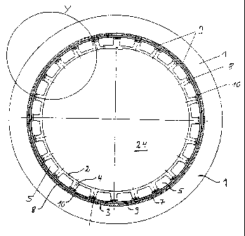
Fig. 6 shows a cross-section through a refurbished sewer
(alternative embodiment);
Fig. 7 shows a cross-section through the refurbished sewer
(detail Y of Fig. 8 after the annular space filling);
85 Fig. 8 shows a cross-section through the sewer being re-
furbished, before the annular space filling;
Fig. 9 shows the attachment of the inliner at the end of the
sewer.
oesoeichert t9 (~9 94 Now~k~tl7A~FtJt O(~('.
21339~~
W70 93/21398 PCTjEP93j00973
- 11 -
Best Mode for Carrying Out the Invention
A sewer 1 with nominal diameter of 300 mm (DN 300) is to be
refurbished. Sewer 1 has standard manhole structures 14 spaced
~M
every 60 m (Fig. 4).
To produce the preliner 7, a preparation consisting of
97a by weight HDPE (Vestolen~ A 3512 Natur; Hails AGf
modulus of elasticity 590 N/mm2)
2~ by weight (white pigment PMM 869, Polyplast
Muller)
1o by weight HDPE (Vestolen~ A 3512 R, Huls AG: con-
taining carbon black)
is homogenized in' a single-screw extruder known to those
skilled in the art and extruded onto a rolling mill as a flat
foil faith a w>>dth of about 1 m and an average thickness of
2.5 mm. The rolling mill consists of a first roll with flat
round depressions and a second, smooth roll. In the gap between
the rolls, the thermoplastic material is pressed into the flat
depressions. Removing the sheet from the roll yields a sealing
sheet with nubs 8 with a height of 1 mm and a diameter of 8 mm.
~-lfter trimming the sheet on both sides to a width of 985 mm,
the Sheet is farmed in a second work step into the preliner 7
with an outer diameter of 300 mm, whereby a double weld with an
intervening inspection channel is created in the overlap area
by thermal welding.
For the middle inliner 3; a three-layer HDPE sealing sheet with
sandwiched aluminum foil 10 is employed as a permeation
barrier. Welding to the middle inliner 3 is accomplished as for
the outer inliner (preliner 7).
To produce the inner inliner 2, pure HDPE (Vestolen~ A 3512
Natur; Huls AG; modulus of elasticity: 590 N/mm2) is used.
This preparation is homogenized in. a single-screw extruder and
extruded onto a rolling mill comprising a first roll with
slightly conical holes and a second roll. In the gap between
the rolls, the thermoplastic material is pressed into the
noanoinhort 10 PX7 Qd Alrnara4O1t1x1~GAlt f1llP'
_ X133996
WO 93/21398 PCT/EP93/00973
- 12 -
slightly conical holes. Removal of the sheet from the roll
yields a sealing sheet 13 with nubs. The nubs, with an initial
length of 13 mm, are then compressed at the head using a second
rolling mill comprising a steel roll and a rubber ro'11, with a
gap width of l2 mm, so that the individual nubs 4, compressed
to 'a length of 10 mm, have corresponding undercuts 11. In the
embodiment shown, the sealing sheet 13 is 3 mm thick. The nubs
4 have a length of 10 mm and a diameter at the base of 5 mm and
at the head of 8 mm.
The translucent (opaque) inner inliner 2 has a global light
transmittance of 53%.
Preliner 7, middle liner 3, and inner liner 2 are each cut to a
length of 60 m, inspected for leaks, and transported to the
site on a cable reel. In Fig. 4, pulling the preliner 7 into
the sewer 1 being refurbished is shown in more detail. The
preliner 7 is pulled into sewer l from the standard manhole
structure 14. Using apparatus I5, the preliner 7 is first
.folded into an approximate U shape and, by means of the cable
16, fed into the sewer 1 via the roller guide 17 and the
redirection device 18.
After pulling in the preliner 7, the middle inliner 3 and the
inner inliner 2 are pulled into the preliner 7 in the same
manner (Fig. 4). Subsequently, at both ends of the inner
inlirier. 2, the nubs 4 are removed for a length of 10 cm. These
nub-free ends 31 of the inliner 2 are pressed on both ends
against the sewer interior wall 21 using cutoff bags 19 and 20
and sealed off in this area (Fig. 5). Fill openings 22 and
outlet openings 23 allow the filling and removal of (possibly
tempered) water 24 under defined pressure. At the same time,
any leakage can be detected in time by testing for a drop in
pressure. By virtue of the water-related interior pressure of
about 0.5 bar, the inner inliner 2. is pressed against the
middle inliner 3, which is pressed against preliner 7, which is
pressed against the inner wall 22 of sewer 1, whereby the nubs
4 fix a defined annular space 5 between the sealing sheet 13
and the middle inliner 7. A low-viscosity mortar 6 (brand name
nPCr~r~~s.p~r to n4 as Nr,u~wnn~n~Fnt~ nnr
~33~~~
WO 93/21398 PCT/EP93/00973
- 13 -
HClHT Relining Injector, Huls Troisdorf AG) is injected into
this annular space 5 via the filling funnel 25. In the example
shown, the mortar 6 is injected at low pressure from the crown
of the lowest point of the sewer pound, whereby the mortar 6 is
accordingly distributed by gravity within the annular space 5
of the slightJ_y inclining sewer 1. In Fig. 5, the current
mortar level 26 is depicted. Air can escape as necessary from
the annular space 5 through ventilation ducts 27 and 28, and at
the same time the current mortar level 26 can be monitored.
When injecting the mortar 6, the interior pressure in the inner
inliner 2 can increase under certain conditions; this can be
monitored and compensated for using overfJ.ow 29.
After mortar inject.ian is complete, the mortar 6 hardens within
about 7 hours, whereby the hardening time can be accelerated or
retarded by tempering the water 24.
After hardening, the mortar 6 forms a rigid, self-supporting
pipe that is reliably protected from corrosion from the inside
by the inner inliner 2 and from the outside by the middle
inliner 3. The nubs 4 provide anchoring of the nubbed sheet in
the mortar pipe (Fig. 7).
Finally, as shown in Fig. 9, the inliner 2 is attached at both
ends to the manhole structures 14. For this purpose, a
statically self-supporting, rigid HDPE ring 30 is inserted from
the manhole structures l4 into the end of the sewer, whereby
the nub-free ends 31 of the inliner 2, together with the end of
the middle inliner 2 and the end of the preliner 7, are clamped
between the HDPE ring 30 and the sewer inner wall 21.
Furthermore, an inspection tube 36 provides access to the
inspection space 9 between the outer inliner 7 and the middle
inliner 3. As shown in Fig. 9, the middle inliner 3 is
additionally welded to the outer inliner 7 at the inliner end,
i.e., at the manhole structure 14 (weld 37). A sealing band 32
of butyl rubber (double-sided adhesive band) serves as a
further seal between the inliner ends 31 and the middle inliner
3. After insertion of the HDPE rings 30, the latter are welded
to the inliner 2 (weld 33). Finally, a semicircular-arc-shaped
...,~....t..w...~ ~n nn n~ m.......mnn~~~cma nnr
WO 93/21398 PCT/EP93/00973
- 14 -
HDPE plate 35, fastened from the manhole structure 14 at the
upper half of sewer pipe 1 with dowels 39, is welded to ring
30.
_M
The use of a nearly transparent inliner 2 permits reliable TV
monitor. ing o.f the annular space 5, f i l_l.ed with mortar 6, so
that, for example, large air bubbles can be detected in time.
In Figs. 8 and 7, a cross section of an accordingly refurbished
pipe is shown. Between the outer iriliner (preliner 7) and the
middle inliner 3, an inspection space 9 (outer annular space)
is fixed by the nubs 8.
Fig. 6 depicts an alternative embodiment of the invention in
which the inner pipe 38 is formed from a resin-impregnated
flexible fleece tube.
_~~~~~~6
WO 93/21398 PCT/E,P93/00973
- 15 -
Legend
1 Sewer pipeline sewer
2 Inner thermoplastic inliner
.,.
3 Middle inliner
4 Nubs
5 Annular space
6 Mortar
7 Otzter inliner (preliner)
8 Nubs
9 Annular space, inspection space
10 Metal foil
11 Undercuts
12 Inherently rigid inner pipe
13 Sealing sheet
14 Manhole structure
15 .Apparatus
16 Cable
17 Roller guide
18 Redirection device
19 Cutoff bag
20 Cutoff bag
21 Sewer interior wall
22 Fill opening
23 Outlet opening .
24 Water
25 Filling funnel
26 Mortar level
2? Ventilation duct
28 Ventilation duct
29' Overflow
30 Ring
31 Nub-free inliner end
32 Seal
33 Weld
8~ 34 Dowel
HDPE plate
36 Inspection tube
37 Weld
38 Inner pipe
rtocnai~horl 10 f10 Qd AIrr~Wlflll'MiFAII f1lll'