Note : Les descriptions sont présentées dans la langue officielle dans laquelle elles ont été soumises.
~ ~13S6S8
PRESSING APPARATUS FOR FOLDED PRINTING PRODUCTS
SUCH AS NEWSPAPERS, PERIODICALS AND PARTS THEREOF
Background of the Invention
The present invention relates to an apparatus
for pressing folded printing products, such as
newspapers, periodicals and parts thereof.
Such pressing apparatuses serve for
compressing folded, multi-sheet printing products in
the region of their fold and pressing out the air
trapped between the sheets.
US Patent No. 3,257,110 discloses such a
pressing apparatus in which one of the pressing rollers
of the pair of pressing rollers is mounted rotatably in
pivotably mounted arms and is drawn by means of tension
springs acting on these arms against the fixedly
mounted, other pressing roller of the pair of pressing
rollers.
It is an object of the present invention to
provide a pressing apparatus of the described type and
which, while of a space-saving design, is able even at
a high conveying speed of the printing products to
press the latter together very strongly and permanently
in the fold region, without the printing products being
damaged thereby.
21 35658
-
SUMMARY OF THE INVENTION
The above and other ob~ects and advantages of the
present invention are achleved by the provislon of an
apparatus for pressing folded prlntlng products whlch are fed
in an lmbrlcated formatlon wlth the leadlng fold edges
extendlng at rlght angles to the conveylng dlrectlon,
comprlslng a flrst palr of rotatably mounted pressing rollers,
which deflne between them a passage nlp for the prlntlng
products and lncludlng a first presslng roller and a second
pressing roller, means flxedly mounting said flrst presslng
roller, and means mountlng sald second presslng roller so as
to permit lt to be forced transversely to the conveylng
dlrectlon of the prlntlng products agalnst the actlon of an
elastic restoring force and away from the flrst pressing
roller, a second palr of presslng rollers, mounted downstream
of said first pair of pressing rollers and whlch llkewlse
deflne between them a passage nlp for the prlntlng products
and lncludlng a flrst presslng roller and a second presslng
roller, means flxedly mountlng sald flrst presslng roller, and
means mounting sald second presslng roller so as to permit lt
to be forced transversely to the conveylng dlrectlon of the
prlntlng products agalnst the actlon of an elastlc restorlng
force and away from the flrst presslng roller, drlve means for
drlvlng all of the pressing rollers lndlvldually, sald drive
means comprlslng at least one endless drlve element of
elastlcally extenslble materlal, whlch ls passed over each of
sald pressing rollers and a drive roller, and wherein the
flrst, flxedly mounted presslng rollers of both palrs of
25561-97
- 21 35658
-2a-
presslng rollers are arranged on that side of the lmbrlcated
formatlon on whlch the fold edges of the prlntlng products lle
freely.
The present lnventlon also provides an apparatus for
processlng folded prlntlng products, comprlslng means for
feedlng the folded prlntlng products ln an lmbrlcated
formatlon wlth the leadlng fold edges extendlng at rlght
angles to a conveylng dlrectlon, a flrst palr of rotatably
mounted presslng rollers, whlch deflne between them a passage
nlp for the prlntlng products and lncludlng a flrst presslng
roller and a second presslng roller, means flxedly mountlng
sald flrst presslng roller, and means mountlng sald second
presslng roller so as to permlt lt to be forced transversely
to the conveylng dlrectlon of the prlntlng products agalnst
the actlon of an elastlc restoring force and away from the
first pressing roller, a second palr of pressing rollers,
mounted downstream of sald flrst palr of presslng rollers and
which likewlse deflne between them a passage nlp for the
prlntlng products and lncludlng a flrst presslng roller and a
second presslng roller, means flxedly mountlng sald flrst
presslng roller, and means mountlng sald second presslng
roller so as to permlt lt to be forced transversely to the
conveylng dlrectlon of the printlng products agalnst the
actlon of an elastlc restorlng force and away from the flrst
presslng roller, drlve means for drlvlng all of the presslng
rollers lndlvldually, and whereln the flrst, flxedly mounted
presslng rollers of both palrs of presslng rollers are
arranged on that slde of the lmbrlcated formatlon on whlch the
- 25561-97
21 35658
-2b-
fold edges of the prlntlng products lie freely.
The prlntlng products preferably have their leading
fold edges facing the fixedly mounted pressing rollers, and
particularly effectlve pressing takes place in the fold
region, slnce the pressing rollers acting dlrectly on the fold
edges cannot be forced back. This effective pressing, acting
gently on the products, is further assisted by the pressing
rollers being individually driven.
The fold region is permanently formed by the strong
pressing, so that later no reversion of the fold occurs, which
is of great advantage for the subsequent further processing.
EP-A-O 417 621 and the corresponding US Patent No.
5,125,330 disclose a pressing apparatus for
f 25561-97
~ ;~13S6~8
printing products in which the products likewise run
through two pairs of rollers, arranged one behind the
other, each with a fixedly mounted roller and a
resiliently mounted roller. Of these two pairs of
rollers, however, only one pair of rollers serves for
the actual product pressing, while the other pair of
rollers is formed by guide rollers. The latter are not
absolutely necessary, since they only serve, as
mentioned, for guidance of the products pressed by
means of the first pair of rollers. In the case of
this known apparatus, it is also provided for the
products to be passed through the pressing and guiding
rollers in an imbricated formation such that the fold
edge comes into contact with the fixedly mounted
rollers. However, this pressing apparatus is designed
for a different purpose, it serves for the pressing of
printing products which run through the pairs of
rollers with one corner ahead, i.e., with their fold
edge slanted with respect to the conveying direction.
Brief Description of the Drawinqs
An exemplary embodiment of the subject of the
invention is explained in more detail below with
reference to the drawing, in which, purely
diagrammatically:
Fig. 1 shows in side view and in simplified
representation part of an apparatus for pressing folded
printing products running past in imbricated formation,
Fig. 2 shows in a side view corresponding to
Fig. 1 the entire pressing apparatus,
Fig. 3 shows half of the pressing apparatus
according to Fig. 2 in plan view, certain parts being
cut away,
Fig. 4 shows a detailed representation of a
guide element used in the pressing apparatus,
Fig. 5 shows a section along the line V-V in
Fig. 2, and
~1356S8
Fig. 6 shows a simplified view of the
pressing apparatus in the direction of the arrow A in
Fig. 5.
Detailed Description of the Preferred Embodiment
With reference to the simplified
representation of Fig. 1, the basic construction of the
pressing apparatus is explained below. The more
specific construction of the pressing apparatus will be
described later with reference to Figures 2-6.
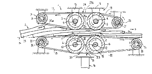
The pressing apparatus has a first pair of
pressing rollers 1 and a second pair of pressing
rollers 2, arranged adjacent to the latter. The two
cylindrical pressing rollers of each pair of pressing
rollers 1 and 2 are denoted by 3 and 4 or 5 and 6,
respectively. The pressing rollers 3 and 4 or 5 and 6
of each pair of pressing rollers 1 and 2 define between
them a passage nip 7 or 8, respectively. The pressing
rollers 3, 4, 5, 6 are mounted rotatably on spindles 9,
10, 11 and 12, respectively. In this case, the
spindles 9 and 11 of the two upper pressing rollers 3
and 5 are held fixedly in bearing parts, which in Fig.
1 are only diagrammatically represented and are denoted
by 13 and 14. On the other hand, the spindles 10 and
12 of the two lower rollers 4 and 6 are mounted in a
common mounting 15, represented only diagrammatically
in Fig. 1, which is supported on pneumatic springs 16.
The mounting 15, and consequently the pressing rollers
4 and 6, are consequently resiliently supported
displaceably in the direction of the arrow B on the
pneumatic springs 16, as will be described in more
detail later.
The pressing rollers 3, 4, 5, 6 are driven
individually by means of endless drive belts 17, 18, 19
and 20, respectively, of a flexibly extensible
material, for example rubber. These drive belts 17,
18, 19, 20 run in grooves in the assigned pressing
~135G58
--5--
rollers 3, 4, 5, 6 over these pressing rollers 3, 4, 5,
6 and also over drive rollers 21, 22, 23 and 24, which
are fastened on fixedly, but rotatably mounted spindles
25, 26, 27 and 28, respectively. The drive arrangement
for driving the drive rollers 21, 22, 23 and 24 will be
explained in more detail with reference to Fig. 2.
Thanks to their flexible extensibility, the drive belts
17, 18, 19, 20 are capable of compensating for
variations in the circumferential speed of the pressing
rollers 3, 4, 5, 6. Such speed variations are caused,
for example, by differences in the thickness of the
imbricated formation running through the passage nips
7, 8.
Also passed over the drive rollers 21 and 23
on the one hand and the drive rollers 22 and 24 on the
other hand are endless, flexible guide elements 29, 30,
which run further over the pressing rollers 3 and 5 or
4 and 6, respectively. In Fig. 1, these guide elements
29, 30 are only partially visible, namely only the
sections 29a, 29b and 30a, 30b which span and cover the
intermediate space 31 and 32 between the pressing
rollers 3 and 5 or 4 and 6, respectively. The
arrangement of the drive belts 17, 18, 19, 20 and of
the guide elements 29, 30 can be seen from Fig. 3.
In Fig. 1 there is also shown part of an
imbricated formation S comprising printing products 33
lying one on top of the other in the manner of roof
tiles. In this case, each printing product 33 rests on
the preceding printing product, so that the leading
fold edge 33a of each printing product 33 lies on the
upper side of the imbricated formation S. A feed
conveyor 34, serving for feeding the imbricated
formation S, is only indicated entirely
diagrammatically.
The printing products 33 run through the
passage nips 7, 8 of the pairs of rollers 1 and 2 and
are thereby pressed together.
~13~1~ a 8
--6--
The complete construction of the pressing
apparatus is now explained with reference to Figures 2
to 6.
In Fig. 2 the entire pressing apparatus is
shown in side view. The components already explained
with reference to Fig. 1 can also be seen in this Fig.
2, but to preserve better overall clarity not all these
components are provided with the assigned reference
numerals. With reference to Fig. 2 together with Fig.
3, in particular the drive system for the pressing
rollers 3, 4, S, 6 is explained. In the Figure showing
a plan view, Figure 3, only half of the apparatus is
shown, certain parts having been omitted or cut away.
The components explained with reference to
Fig. 1 are arranged or mounted in a frame 35. In this
frame there is also an only diagrammatically
represented drive 36, which drives the drive rollers
21, 22, 23 and 24 via an endless toothed bolt 37,
provided on both sides with a toothing. The toothed
belt 37 is passed over a gearwheel 38, which is seated
on the spindle 28 which is driven by the drive 36 and
to which the drive roller 24 is connected non-rotatably
(Fig. 3). As Fig. 2 reveals, the gearwheel 38 turns
clockwise and the toothed belt 37 moves in the
direction of the arrow C. From the gearwheel 38, the
toothed belt runs over deflecting rollers 39, 40 and 41
to a gearwheel 42 (Fig. 3) which is seated on the
spindle 26 to which the drive roller 22 is connected.
From this gearwheel 42, the toothed belt 37 is passed
over a gearwheel 43 (Fig. 2) which is connected non-
rotatably to the drive roller 21 (not shown in Fig. 3).
From this gearwheel 43, the toothed belt 37 runs over
deflecting wheels 44, 45, 46 and 47 to a gearwheel 48
(see Fig. 3) and from the latter to the already
mentioned gearwheel 38. This gearwheel 48 is seated on
the spindle 27, to which the drive roller 23 is
connected non-rotatably.
--- 213 5 6 .) 8
As can be further seen from Fig. 2, the
pneumatic springs 16 are connected via a pressure line
49 to a pressure control unit 50, which is connected to
a compressed air connection 51. By means of the
pressure control unit 50, the pressure inside the
pneumatic springs 16, and consequently also the force
exerted by the compression springs 16, is set to
particular values in each case.
As mentioned, the arrangement of the drive
belts 17, 18, 19, 20 of the guide elements 29 and 30
can be seen from Fig. 3, these drive belts and guide
elements being represented partially cut away. As Fig.
3 reveals, the drive belts 17, 18, 19, 20 are arranged
laterally of the pressing rollers 3, 4, 5, 6, while the
guide elements 29, 30 are arranged such that they are
distributed over the length of the pressing rollers 3,
4, 5, 6 and offset with respect to one another.
As is evident from Fig. 1 in particular, the
guide elements 29, 30 serve for guiding the fed
printing products 33 into the passage nip of the first
pair of pressing rollers 1 and for covering the
intermediate space 31, 32 between the pressing rollers
- 3 and 5 and also 4 and 6, in order that the printing
products 33 cannot penetrate into this intermediate
space 31, 32 but reach the passage nip 8 of the second
pair of pressing rollers 2. Consequently, the guide
elements 29, 30 come into contact with the printing
products 33. If the pressing apparatus shown is
arranged in the direct vicinity of the output of a
rotary printing machine, there is therefore the risk of
smearing the not yet quite dry printing ink. To avoid
this, the guide elements 29, 30 are produced from a
thin, helically wound wire 52, such as that shown in
Fig. 4. The guide elements 29, 30 are consequently
designed as long and thin helical springs.
~13S658
--8--
The type of mounting of the pressing rollers
3, 4, 5 and 6 is now to be described with reference to
Figures 5 and 6.
The pressing rollers 3, 4, 5 and 6 are
mounted by means of ball bearings 53 and 54 on the
assigned spindle 9, 10, 11 and 12, respectively. The
fixed spindles 9 and 11 of the upper pressing rollers 3
and 5 are held in bearing bushes 55 and 56, which are
firmly attached on the frame 35. All the pressing
rollers 3, 4, 5, 6 are provided on their circumference
with grooves 57, into which the guide elements 29 and
30 come to lie.
The spindles 10 and 12 of the lower pressing
rollers 4 and 6, respectively are likewise held in
bearing bushes 58 and 59, which are attached on a
bearing plate 60 and 61, common to both pressing
rollers 4 and 6. Each of these bearing plates 60, 61
is connected by means of a connecting bolt 62 and 63 to
the one leg of an L profile 64 and 65, respectively.
These connecting bolts 62, 63 extend through a slot 66
~Fig. 6) in a side wall 35a and 35b, respectively, of
the frame 35. The other leg of the L profile 64 and 65
is firmly connected to the upper end of the assigned
pneumatic spring 16. On this leg of the L profile 64
and 65 there rest in each case two damping elements 67,
68 of rubber, which belong to a setting device 69,
which is represented in Fig. 5. The damping elements
67, 68 are fastened on a plate 70, or 71 respectively,
which is firmly connected to a tube piece 72, 73 with
an internal thread. In the internal thread of the tube
pieces 72, 73 there engages a threaded bolt 74, 75,
which is mounted rotatably in a guide part 76 and 77
fastened on the frame wall 35a and 35b, respectively.
Each threaded bolt 74, 75 is connected non-rotatably to
a bevel gear 78 and 79, respectively, which is in
engagement with a further bevel gear 80 and 81,
respectively. The bevel gears 80 and 81 are seated
- ~13~6~8
non-rotatably on a shaft 82, which can be turned by
means of a hand wheel ~3. For arresting the shaft 82,
a manually operable arresting device 84 is provided.
By means of the setting device 69, the size
of the passage nips 7 and 8 can be set. By turning the
hand wheel 83, the plates 70 and 7~ with the damping
elements 67 and 68 are raised and lowered. This
raising and lowering movement of the damping elements
67, 68 is transferred to the L profiles 64, 65, which
has the consequence of a corresponding raising and
lowering of the spindles 10 and 12 and of the pressing
rollers 4 and 6 mounted on the latter. The pneumatic
springs 16 follow this movement of the L profiles 64,
65. In Figures 2, 5 and 6, the pressing rollers 4 and
6 and the components moving along with the latter are
shown by dot-dashed lines in their lower end position
and are denoted by the assigned reference numerals,
provided with a '. As Fig. 6 shows, the pressing
rollers 4' and 6' located in the lower end position are
no longer in contact with the upper strand of the guide
elements 30 ' . In this lower end position of the
pressing rollers 4', 6', no pressing of the printing
products 33 takes place any longer.
To the extent that it has not already emerged
from the above description, the pressing operation is
further explained below.
The printing products 33 fed in conveying
direction F to the first pair of pressing rollers 1 are
passed via the guide elements 29, 30 to the passage nip
7 between the pressing rollers 3 and 4. On running
through this passage nip 7, a first pressing of the
printing products 33 takes place. For strong
compressing of the printing products 33 it is important
that the upper-lying fold edges 33a of the printing
products 33 come into contact with the fixed pressing
roller 3. The printing products 33 then pass into the
second passage nip 8 between the pressing rollers 5 and
~ ~ 1 3 5 6 ~ 8
--10--
6 of the second pair of pressing rollers 2. The
sections 29a and 30a of the guide elements 29 and 30
prevent the printing products 33 being able during this
movement by them to enter into the intermediate space
31 or 32 between the pressing rollers 3 and 5 or 4 and
6, respectively. On running through the second passage
nip 8, a repeated pressing together of the printing
products 33 takes place.
The lower pressing rollers 4, 6 are
resiliently supported by the pneumatic springs 16,
which makes it possible for these pressing rollers 4, 6
to follow the differences in thickness in the
imbricated formation S. By the use of pneumatic springs
16, which respond more quickly to loading variations
than helical springs, it is possible to correct the
pressing rollers 4, 6 all the time to the contour of
the imbricated formation S. The force which the
compression springs 16 exert can be changed in a simple
way by means of the pressure control unit 50 and set to
the value desired in each case. The described design
of the mounting of the shafts 10, 12 of the pressing
rollers 4, 6 also permits a certain pivoting or locking
movement of the bearing plates 60, 61 about the
longitudinal axis of the connecting bolts 62, 63. This
pivoting movement is damped by the damping elements 67,
68.
If there has to be processed an imbricated
formation in which, other than as shown in Fig. 1, each
printing product rests on the following printing
product and the leading fold edge consequently lies on
the lower side of the imbricated formation, the fixed
and sprung pressing rollers must be interchanged, i.e.
the fixed pressing rollers are then to be arranged on
the lower side of the imbricated formation in order
that they can act directly on the fold edges of the
printing products in this case as well.
- ~13~û~8
--11--
In the drawings and specifications, there has
been set forth a preferred embodiment of the invention,
and although specific terms are employed, they are used
in generic and descriptive sense only and not for
purpose of limitation.