Note : Les descriptions sont présentées dans la langue officielle dans laquelle elles ont été soumises.
CA 02135803 2002-07-24
STEP SWITC~-i
FIELD OF THE INVENTION
The present invention relates to a step switch with
a step transformer.
BACKGROUND OF THE INVENTION
Such step swatches with a step transformer are known
from Siemens-Zeitschrift a0 (1976) column 1, pages 9
through 17, "Ofentransformatoren...," by Robert Brehler.
German patent 3,630,415 describes using a
conventional oil-filled step switch which is mounted on a
support laterally ad;acent: the transformer and which is
connected electrically by cannectaon lines.
Swiss patent 391,UF38 further describes an
arrangement where the connections are extended out of the
transformer to contacts which are arranged like a collar
around the per.iphe ry of a cylindrir_:al housing in which
the step switch is recessed so that same is connectable
by respective contacts on the outside of the step-switch
housing electrically with the collar of contacts and
therethrough with the transformer.
Another built-on step switch of the load-selector
type for oil transformers is known from German published
application 2,712,484 which has a grid that fixes and
guides the connection lanes between. the step contacts and
the respective transformer.
Finally a cast-resin transformer is known from
Japanese utility model 62-10973 wherein the connections
of the step winding are extended to a cast-in-place
contact plate whence they are extended by electrical
connector lines to a step switch.
All these known arrangement. have substantial
disadvantages.
- 1 -
CA 02135803 2002-07-24
First in every case there are a plurality of
electrical connections on the step switch with the
respective taps of the transformer by means of numerous
electrical lines. This is expensive, requires special
means for mechanically fixing these conductors and for
avoiding electrical interaction, and does not in addition
allow for a change o:E connectors fc~r example during
assembly or repair. It is further disadvantageous that the
adjacent step switch must be fixed near the transformer by
means of special holders, traverses, struts, or the like
that are not normally provided orn or needed by the
transformer. This means further that true rs~spective step
switch must not only be matched in every case to the
electrical characteristics of the transformer, its number
of steps, and so on, but also to the respective mechanical
and constructive c:ircumst.ances, such as siwe, type, style,
and position of the electrical connections and of the
mechanical mounting means and so or~. This leads to an
undesired multiplication of the types of step switches
that must be provided.
SUMMARY OF THE INVENTION
It is an object of the invention to provide a built-
on step switch which is simply electrically connected to
and mechanically mounted on step transformers, in
particular on cast-resin insulated step transformers of
different types and con:~truction. rI'his object is solved
according to the invention by the technical. features laid
out in patent claim 1.
The dependent claims contain particularly
advantageous embodiments of the invention.
This invention has numerous advantages. To start with
there are none of the-prior-art standard connections with
all of their known problems, possibility of mistake, and
- 2 -
CA 02135803 2002-07-24
the like since the modular step sw.it.ch according to the
invention is mounted directly on the z°espective cast step
winding of the transformer. In addition this very direct
connection of the step switch and the electrical
connections as well as the mechanical mounting means in a
single space eliminates expensive mounting devices,
supports, traverses, and the like. Due to the
corresponding "section .places" on the step transformer and
on the step switch s:impie configurations a:re possible. The
technical embodiment of the step switch as identically
constructed single-phase step switch modules has the
advantage of maximum simplification.
The step-switch modules have one-piece connector
elements and mounting means by means of which they are
connectable directly with the connection and contact means
on the cast-resin transformer. In a particularly
advantageous embodiment of the invention the housing of
the step-switch module has at. least one cavity through
whose interior in mounted condition the mounting and
connector elements of the step transformer extend and by
which they are directly actuatable as step contacts. To
this end these connector elements are formed on their free
ends preferably as electrodes and are arranged in a circle
or along a straight line.
It can be advantageous in a further embodiment of the
invention to connect the step-switch module mechanically
and electrical~.y via contact and/or mounting adapters
with the respective Step transformers. In this manner no
change in the step-switch module itself is necessary to
fit it to changed connector and mounting systems but only
a relatively simple different adapter is needed.
A cast-resin transformer has a transformer housing, a
plurality of windings each having a plu.rali.ty of taps,
respective contacts connected to the taps a.nd mounted on
- 3 -
CA 02135803 2002-07-24
the housing in respective arrays which are all identical,
and respective identical mounting elements on the housing
at each of the contact arrays. Respective identical step
switches each serve a respective winding of the
transformer and each have a switch housing secured to the
respective mounting element of the transformer housing at
the respective contact array and a step contact movable
along the respective connector elements and electrically
engageable therewith. A dn~ive motor- and a main shaft are
connected to all of the step contacts for synchronously
stepping the step contacts along tale respective connector
elements.
BRIEF DESCRIPTION OF THE DRAL~IINGS
The invention is described below by way of example
with reference to the drawings.
FIG. 1 shows schematically the arrangement of a
modular step switch according to the irment~ion with a
cast-resin step tx-ansformer.
FIG. la shows are alternative arrangeme>nt .
FIG. 2 shows in a perspective view the>. interactive
connection and mounting elements.
FIG. 3 shows a second embodiment of these elements
also in perspective view.
FIG. 4 shows a 'third embodiment of these elements
also in perspective view.
FIG. 5 shows in section from above a further
embodiment of a modular step switch according to the
invention.
FIG. 6 shows a possible switching system for one of
these step switches.
- 4 -
CA 02135803 2002-07-24
DETAILED DESCRIPTION OF THE PREFERRED EMBODIMENT
A three-phase step transformer 1 which is formed as
a cast-resin transformer has for each phase a connection
terminal 2.1, 2.2, and 2.3. These connection terminals
2.1, 2.2, and 2.3 have in respective similar geometric
arrangements electrical. connection elements 2.1.1, 2.2.1,
and 2.3.1 which are each connected with the respective
taps of the step winding of the respective phase. They
further have mechanical. mounting means 2.1..2, 2.2.2, and
2.3.2. Each connection te..rminal. is electrically and
mechanically connected to a respective single-phase
identically constructed si.-ep-switch modules 3.1, 3.2, and
3.3. The connection is made by electrical connector
elements 3.1.1, 3.2.1, an<:~ 3.3.1 as well a.s by
corresponding mechanical mounting means 3.1.2, 3.2.2, and
3.3.2 at the respective step-switch modules.
The joint synchronous actuation of the step-switch
modules is done by drive shafts 4.1, 4.2, 4.3 which are
connected to a common motor drive 5. FIG. 1a shows
schematically a further example of the arrangement of the
drive shafts. with the drive motor 5 having an output
shaft 4.4 connected via a right angle drive 4.5 to a
secondary shaft 4.5 connected through respective right-
angle drives 4.7 with the drive shafts ~,1, 4.2, and 4.3
of the respective step switches 3.1, 3,2, and 3.3.
FIG. 2 shows a connection terminal 2.1. of the step
transformer 1 as well as a hereto connected step-switch
module 3.1 in more detail. A plurality of connector
elements 2.1.1 arranged vertically <above one another each
correspond to a respective tap of the step winding and are
constituted as plugs; flanking them are mounting means
2.1.2, for example studs. The step-switch module 3.1 has
geometrically complementary electrical connector elements
3.1.1 formed as contact sleeves or clips which grip the
CA 02135803 2002-07-24
connector elements 2.1.1 and also has complementary
mounting means 3.1.2, in this case bores in a flange, so
that the step-switch module 3.1 can be secured by nuts
with the respective connector terminal 2.1.1. The
complementary construction of the interengaging pairs of
electrical connector elements and mechanical mounting
means can be set up any way depending on the respective
electrical requirements and load and. the mechanical and
spatial relationships. It is sure that in every case only
a single step-switch module is necessary regardless of the
number of phases of r_.he transformer.. Each step-switch
module is a complete single-phase step switch in
particular equipped with i.ts own force-storage unit for
snap actuation. Such step-switch modules are particularly
advantageous as single-phase load selectors which can be
made particularly small when they combine :step
preselection and noninterruptive load switching. It is
furthermore naturally particularly advantageous to make
the step-switch modules i.n dry construction since then no
separate sealing of the oil chamber is necessary. Finally
it is also possible to form the step-switch modules as
load-free switching selectors, linear selectors, and the
like so as to further simplify the entire arrangement
since for example the force-storage unit is not needed and
also before switching from one step to the next the
transformer is shut off.
It is further advantageous to form the electrical
connector elements on the connector terminal so that they
extend into the interior. of the closed step-switch module
and there are switched directly as contacts between which
the switching takes place. - Such an arrangement is shown
in FIG. 3. Here with a connector terminal 2.1 unchanged
from FIG. 2 the electrical connector elements 2.1.1, which
are also arranged in a vertical row, are formed on their
- 6 -
CA 02135803 2002-07-24
free ends as electrodes. The step-switch module 3.1 fixed
on the connector terminal 2.1 does in fact have
corresponding mounting means 3.1.2 but no separate
electrical connector elements are provided. On the
contrary there is in the housing of the step-switch module
3.1 a cavity 3.4 which is open toward the connector
terminal 2.1 and in which the electrode-like free ends of
the electrical connector elements 2.1.1 extend into the
Anterior of the step-switch module 3.1 and there directly
form the fixed switchabl.e step contacts of the step
transformer on which at least one movable step-selector
and/or load-selector contact 3.5 engages.
FIG. 3a shows an alternative arrangement of the
electrical connector elements; this circular arrangement
is also ideal in order to form the fixed step contacts
directly which then are switched by a centrally pivotal
contact bridge in the known manner.
FIG. 4 shows a i=urther embodiment. Here the step
switch module 3.1 also has a cavity 3.4 which i.s open
toward the connector terminal. 2.1. As a variation of the
invention here however the electrical conductors are
formed as cast-in-place threaded sleeves 6.1.1 ... 6.5.2
where each electrical connection has two adjacent threaded
sleeves 6.n.1 and 6.n.2. Parts 7.1 ... 7.5 screwed to the
pairs of adjacent threaded sleeves form step contacts
7.1.1 ... 7.1.5 which work with a movable contact 3.5 and
which have tabs 7.2.1 ... 7.2.5 on which the step-switch
module is mounted. Thus the functions of the electrical
connector elements and the mechanical rnount:ing means are
combined.
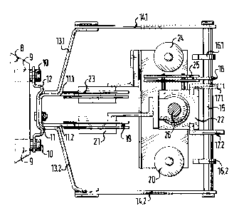
FIG. 5 shows from above a single-phase step switch
according to the invention. A cast-resin transformer has
on the front side of each winding 8 a vertical row of
contact sleeves 9 which are each connected with a tap of
CA 02135803 2002-07-24
the step winding as has been described above. In this
embodiment two threaded. sleeves 9 at the same potential
are arranged horizontally next to each other and are
secured by bolts 10 with the respective one-piece step
contact 11 directly or via a conductive spacer 12. Each of
the identically formed step contacts 11 which are arranged
in a vertical row has two parallel contact blades 11.1 and
11.2 which extend parallel. to each other inside the
housing of the step switcru.
The two contact blades 11.1 and 1:1.2 are bolted to
two housing parts 13.1 arid 13.2 which are symmetrical as
seen from above; these form with two side plates 14.1 and
14.2, for example of insulating material, and two
horizontal guide bolts 15 the housing of the step switch.
In this system the rear side of the housing that is turned
away from the fixed contacts is open; it i;s of course also
possible to provide a closed cover plate o:r the like
instead of the two parallel horizorutal spacer bolts 15.
Between the horizontal spacer bolts 15 and extending
vertically parallel to each other is at least one, here
two, cam rails 16.1 and 16.2 and at least one, here two,
guide rails 17.1 and 17.2 and at least one output rail 18.
In addition ser_ured to unillustrated st:.ruts inside the
housing -- also extending vertically tYnrough same -- is a
further contact rail 19 which is connected via a not
further illustrated shunt resistor R and a switch 20 with
the output rail 18.
FIG. 6 shows the schematic of such a step switch
according to FIG. 5. The drive shaft 26 which extends from
above into the housing and which has a threaded spindle
vertically moves a first contact bridge 21 which can slide
over the contact blades 11.2 of the fixed step contacts 11
and also loads a diagrammatically illustrated force-
storage unit 22 vertically in a direction which is
_ g _
CA 02135803 2002-07-24
dependent on the rotation direction. of the drive shaft 26.
Its release is triggered by unillustrated spring-loaded
pawls which are actuated by the carp rails 16.1 and 16.2.
In its snap-action vertical movement in which it follows
the first contact bridge 21, the force-storage unit 22
which carries a seco:rid contact bridge 23 is mechanically
guided by the guide :rails 17.1 and 17.2. Z'he second
contact bridge 23 connects the other contact blade 11.1
of the fixed step contact 11 vi.a a second switch 24 with
the output line 18, preferably through a further contact
bridge 25. The switches 20 and 24 are preferably vacuum
switches whose actuaticn is controlled also by the shape
of the already provided cam rails 16.1 and 16.2.
- 9 -