Note : Les descriptions sont présentées dans la langue officielle dans laquelle elles ont été soumises.
.-
METHOD, APPARATUS AND INSTALLATION POR SURVEYING AND MONITORING
A HYDROCARBON RESERVOIR PENETRATED BY A WELL
The present invention relates to techniques for monitoring and
surveying a hydrocarbon reservoir penetrated by a well. More particularly
the invention concerns a method, and a device for its implementation, in
which at least two electrodes are located in the said well, spaced apart
from each other along the length of the well and connected to a current
source and to means for measuring an electrical parameter, from which a
characteristic of the reservoir is deduced. The parameter is the potential
ox the current and the characteristic of the reservoir is the resistivity
of the geological formations forming the reservoir.
The production of hydrocarbons needs to be controlled and monitored
regularly or continuously, in order to determine the cause of any reduction
or stoppage in production and in order to attempt to remedy it. Apart from
depending on the installed production facility, production also depends on
characteristics of the reservoir, not only static characteristics (i.e.
porosity) but also dynamic characteristics (intercommunication between the
poxes, permeability, etc.). An important item of information in this
respect is the position in the reservoir of the hydrocarbon/water or
hydrocarbon/gas interface.
It is of fundamental importance not only to detect a possible
pocket of water or gas but to know its position at any instant, in order to
avoid the water reaching the production well.
The electrical resistivity of the ground is used in known manner as
a representative characteristic of the reservoir. The resistivity of
hydrocarbons is much higher than the resistivity of the formation water
which carries salt (in a ratio of around 100 to 1). The measurement is
effected upon drilling the production well, with a logging sonde having
electrodes~or with an induction sonde, means being provided to allow the
resistivity of the strata which traversed by the well to be determined.
The presence of the casing presents an obstacle to electrical
measurements. Moreover, this type of sonde has a depth of investigation of
the order of one meter and thus does not allow the characteristics of
CA 02135961 2003-02-20
66262-136
2
reservoirs t.o be surveyed on a large scale.
Ire this context the present :invention provide:> a
method and a. device fo:r surveying, monit=oring and making
measurements on the reservoir itse.Lf, without affecting
production, and in particular for enabling the position of
the hydrocarbon/water :interface to be determined, with a
view to optimizing production.
According to an aspect of the invention, there is
provided a method for :monitor_ing a fluid reservoir traversed
by at least o:ne well, comprising the steps of: providing at
least one electrode fixed in said well and communicating to
the surface; ~ydraulic.a::Lly isolating the sect::ion of said
well in which said electrode is located from the rest of:
said well; providing electrical coupling between said
electrode and said res~=~:rvoir; passing ~a current through said
reservoir; and measuring by means of said electrode an
electrical parameter, ;aher_eby a c:haracteristi.c:
representative of said reservoir can be deduced.
According to another aspect., there .is provided an
apparatus for monitorinc:~ a fluid reservoir traversed by at
least one wel:L, comprising: at least one elecdtrode fixed in
said well and communicat~irrg to the surface; means for
hydraulically isolating t:~he section of said well in which
said electrode is located from the rest of said well; means
for providing electrica:'~ coupling Between said electrode: and
said reservoirr; means ~or° passing a current through said
reservoir; and means f_~:a:~:v measuring by means of said
electrode an elec~trica! paramete:c, whereby a characteristic
representative of said r_~eservo:ir can be deduced.
In one embodiment there is a plurality of
electrodes which are disposed on a support adapted to
CA 02135961 2003-02-20
66262-136
3
maintain a given spacing between the e=Lectrodes and to
isolate the electrodes from one another.
In an embodiment, more particularly applicablE: to
a production. well pass.i:r~g through two regions containing
different hydrocarbons, the support is formed by a section
of rigid metallic casing, with a.n associated electrically
insulating coating.
In another embodiment, more particularly
applicable to an uncaseci we1_l, c.ri_LlPd specifically for
measurement purposes and separate from the production well,
the support is formed by an elongate member of flexible or
semi-rigid, electrically insulating mat=erial.
In a further embodiment, the device includes a
cable having a pluralit°;~ of insulated canductors within an
outer sheath, each conductor having its end portion exposed
to form a respective electrode.
The electrodes are advantageously fixed in the
well by cement injected bet=wee:n the electrodes and the wall
of the well.
The cement prh=ferably teas electrica:L resistivi.ty
in the same order as t:h.at of the ground of the reservoir.
In an embodiment, a plurality of measuring
electrodes and a current injection electrode are fixed i.n
the well, in permanent manner.
Different measurements are effected at at lea~;t
one intermedi<~te elect.r~::~de and relative to di..fferent
electrodes providing cu:rr.ent: return.
In <~ variant an injection electrode, a return
electrode, a :reference e1_ectrode and one or more
CA 02135961 2003-02-20
66262-136
3a
intermediate measuring electrodes) are used, the measuring
electrodes) not being ~~onnectecl to the source, and the
potential difference is measured between the or each of the
intermediate: electrodes) and the reference electrode.
In: order to fo:Llow the' movement of the
hydrocarbon/water interface, measurements spaced apart in
time are made, and the difference between the measurements
is calculated in order '~,o deterrriine a parameter
representative of the movement of said interface.
The current source generates a continuous current,
or a low-frequency alternating c~.urrent"
The invention will be better understood in the
light of the description which follows, referring to
illustrative, non-limiting embodiments, with reference to
the accompanying drawings, in which:
- Figure 1 is a schematic illustration of the
general context of
- 4 -
the invention;
- Figure 2A is an enlarged schematic view of a first embodiment of
a device according to the invention;
- Figure 2B is a schematic sectional view of a well equipped with
the device of Figure 2A;
- Figure 3 is a schematic view to a smaller scale of a second
embodiment of a device according to the invention;
- Figures 4, 5, and 6 show schematically various implementations of
a method according to the invention; and
- Figure 7 is a section on a vertical plane of a model of
geological formations traversed by a borehole and including a hydrocarbon
reservoir.
As shown schematically in Figure 1, a well 10 is drilled in ground
formations 11, the well 10 opening at the surface 12. The well can have a
depth varying from some hundreds of meters to several kilometers, and it
passes through a certain number of distinct, successive rock and geological
formations.
A current +I is injected from the surface at a point A by a conduc-
tive electrode in contact with the wall of the well and thus the correspon-
ding ground formation, and a second electrode B is positioned so that it is
longitudinally spaced apart along the well at a depth greater than the
electrode A. The electrode B forms the return electrode for the current
(-I). It should be noted that other arrangements of current electrodes axe
possible, so long as a current circulates through the formation; thus a
pair of electrodes can be envisioned at the surface, suitably spaced apart
or, as described below, one electrode in the well and one electrode at the
surface.
In theory'it is possible to trace curves called equipotential lines
and denoted by the general references 13, 14, 15, 16 and 17, it being
understood that only some curves have been shown, for reasons of clarity.
The curve 15 is a straight line representing the level of zero current.
The equipotential curves located between the zero curve 15 and the elec-
trode A are concave towards the surface, while the equipotential curves
between the curve 15 of zero level and the electrode B are concave in the
opposite direction.
_ 5 _ ~~.~~~~1
A hatched region 18 bounded by the equipotential lines 16 and 17
corresponds to a region producing hydrocarbons. A cross-hatched region 19
has been shown inside this same layer and symbolizes a pocket of generally
saline water. In fact geological strata producing hydrocarbons frequently
contain regions or pockets of water and/or gas.
It is desirable to allow the water pocket 19 to be located and to
determine its movement or advance towards the well.
Points corresponding to measuring electrodes fixed in the well, in
contact with the geological formations, are denoted by thp letters a, b, c,
d, e. The electrodes a to a each correspond to an equipotential curve, in
order to facilitate understanding of the figure.
The potential difference between a reference electrode R and each
electrode a to a located in the well and in contact with the geological
formations is measured by means of the potentiometer 20, the reference
electrode being preferably located on the surface, at some distance from
the head of the well for example, under conditions ensuring stability of
its characteristics with time. Other things being equal, the measured
potential values depends on the resistivity of the geological formations
encountered.
The presence of the pocket of water or gas 19 has an effect on 'the
geometry of the equipotential curves and thus affects the measurements of
the potential differences carried out at each of the electrodes _a to _e.
The deformation of equipotential curve 15 is indicated symbolically by a
broken line curve 15', it being understood that all of the curves, parti-
cularly those near the pocket 19, are also deformed. This deformation
tends to affect the measurement at each of the measuring electrodes.
Two embodiments will now be described with reference to Figures 2A,
2B and 3 respectively.
In Figure 2A there is shown a first embodiment of a device accor-
ding to the invention, formed by an array of electrodes 21 to 25, it being
understood that the device can comprise a number of electrodes much greater
than in the shown embodiment. These are formed by rings of conductive
material (copper or the like) fixed permanently on a cylindrical tube 26
forming the casing of a production well. The casing 26 has a coating in
the form of a film or jacket of electrically insulating material with the
reference 27 on its outer wall receiving the electrodes. The electrodes 21
' ~~~~~~~ii1
- 6 -
to 25 are connected by contacts 21a, 22a, 23a, 24a and 25a and a cable
connection 28 to electronic means 29 shown symbolically in the figure and
fixed to the outside of the casing 26. The electronic means 29 are
connected to the surface by a electric connecting cable 30, connected to a
current source 31 (alternating or continuous) and processing means 32 for
measuring information received from the region of the electrodes. The
measurements consist in measuring the injected current and the potential
differences between each of the electrodes 21 to 25 and the abovementioned
reference electrode. The electronic means located near to the electrodes
in the well allow the signals received from the electrodes to be shaped for
sending to the surface via the cable 30 and also allow the current or any
other signal to be fed to the electrodes.
Figure 2B shows a production well 10 fitted with the device of
Figure 2A, with casing 26 and a production string 26A passing through two
fluid reservoirs R1 and R2. The reservoir R2, located at a greater depth
than the reservoir R1, communicates with the interior of the string 26A
through perforations 33 (formed in a manner known per se). The arrows
indicate the flow of the fluid (hydrocarbons) from the reservoir RZ to the
interior of the string 26A and thence to the surface. The array of elec-
trodes 21 to 25 is positioned on the casing 26 in the region of the reser-
voir R1 which is not providing fluid to the interior of the string 26A.
Cement 34 is injected in a manner lcnown per se into the annular space
between the outer wall of the casing 26 and the wall 35 of the well 10.
The electrodes are insulated by the casing 26 and the cement 34 from the
rest of the well and in particular from the fluid flowing into string 26A
from reservoir R2.
The means for passing current in the reservoir R1 include an in-
jection electrode I located at the surface, a current source 31 and an
electrical connection connecting the electrode I and the source 31 and the
measuring electrodes 21 to 25.
The measuring means 32 include a reference electrode R located at
the surface and a potentiometer connected to the electrodes 21 to 25.
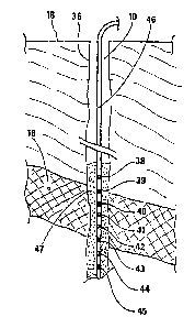
In another embodiment, shown schematically in Figure 3, the device
of the invention comprises a plurality of electrodes 38 to 45, spaced apart
longitudinally in the well 10 and mounted on a tube of small diameter, of
flexible material and having the general reference 46. The tube is lowered
~~~~~61
- 7 -
from the surface 12 into the interior of the well 10, in known manner. The
measurement means and the current injection means are not shown for the
sake of clarity.
The electrodes 38 to 45 are located and fixed permanently in the
well 10 in the region of the production zone 18, by means of an annular
mass of cement 47 injected from the surfar_e, to a depth slightly greater
than the height of the set of electrodes. The cement also ensures elec-
trical coupling of the electrodes to the reservoir, it being noted that the
cement has an electrical resistivity in the same order as the geological
strata encountered. In any event the resistivity of the cement is known,
so that corrections for the presence of the annular mass of cement between
the measuring electrodes and the wall of the well, and thus the correspon-
ding geological formations, can be carried out.
In Figures 2A and 2B, the electrodes 21 to 25 are placed permanent-
ly in the well and they are also electrically coupled to the reservoir by
injecting cement to fill the annular space defined by the outer surface of
the casing and and the wall of the well (not shown in the figures for the
sake of clarity).
It will be understood that different arrangements are possible for
the electrode array. For instance, instead of the above-described support
of insulating material carrying conductive annular sections which form the
electrodes, an electrical cable comprising insulated conductors within an
insulating sheath, in a number at least equal to the desired number of
electrodes, may be used. Each electrode is preferably formed in the same
manner as the well-known "bridle" in a logging cable: each electrode asso-
ciated with a given conductor is formed by the exposed end portion of the
respective conductor itself, that is to say, this end portion has no insu-
lation thereon and passes through the insulating sheath of the cable so as
to lie outside the sheath. Preferably, the exposed conductor is wound
around the cable sheath in a coil-like arrangement, and set in place by
means of an appropriate adhesive or resin leaving exposed the outer part of
the coiled~conductor. Provision is also made to seal the holes which have
to be provided in the outer sheath of the cable in order to pass there-
through the end portions of the conductors, so as to prevent ingress of
well fluids.
In either of the embodiments of the invention (Figure 2B or 3), the
_ 8 - ~:~~~~~1
vertical array of electrodes is located in a well in the region of the re-
servoir, without the electrodes coming into contact with the fluid (hydro-
carbons) flowing into the production well. The cement and/or the casing 26
allow the electrodes to be insulated from the fluid in the well.
In the embodiment of Figure 3, the array of measuring electrodes is
fixed in a well separate from the production well through which the hydro-
carbons are conveyed to the surface. The measurement well where the elec-
trodes are fixed may be a well specifically drilled for this purpose or it
may equally be an existing well now used for measurement. It is possible
for example to drill a well specifically for measurement, relatively
cheaply compared with a conventional well, by a technique called coiled
tubing drilling, in which a casing or rigid metal tube with a relatively
small diameter of some centimeters, is wound on a winch of large diameter
(in the order of 15 meters) and fitted with drilling means at its end.
This technique makes it possible to reduce the drilling costs significantly
and thus to drill a well specifically for measurement purposes at relati-
vely low cost. Only the upper part of the well, extending over some tens
of meters, has a casing 36 known per se.
Various possible ways of implementing the method of the invention
are described below with reference to Figures 4 to 7.
In Figure 4 the elongate support means is shown as a vertical line
50, whether in the form of the casing 26 (Figure 2) or in the form of an
insulating flexible tube 46 (Figure 3). A current source 52 connects an
upper electrode Esup and a lower electrode Einf. The current or potential
source 52 is located at the surface.
A set of electrodes Ei is disposed on the elongated support 50,
preferably spaced regularly between the electrode Esup and the electrode
Einf.
In the implementation in Figure 4, the potential difference is
measured between the reference electrode and one of the electrodes Ei,
called intermediate electrodes.
By way of example, the current or voltage source (referenced 52) is
in the order of 1 amp or several amps.
Other things being equal, it is possible to trace a curve of
potential as a function of depth by making a measurement at each of the
intermediate electrodes Ei. Thus each electrode Ei corresponds to a.given
~~.3~~~'1
- 9 -
depth. Figures 9 and 10 show by way of example such a curve of potential
as a function of depth.
In another implementation, shown in Figure 5, the source of voltage
52 connects the electrode Einf and a given intermediate electrode Ej. The
various potential difference measurements are made at each of the interme-
diate electrodes Ei other than the intermediate electrode Ej connected to
the current source. This variant makes it passable to detect a possible
pocket of water or gas 19 which, in the example shown, is located near the
lower electrode Einf. Thus, in the diagram of Figure 4, the presence of
the pocket of water 19 has little chance of being detected, taking account
of the distance between the electrode Esup and the pocket of water. In the
embodiment of Figure 5, the proximity of the return electrode Ej increases
the chances of. detecting the pocket of water 19.
Coupling and connection means, including the cable 35, known in
themselves and not shown, are provided in order to connect the current
source 52, located at the surface, to any one of the electrodes to provide
the current input electrode and to any one of the electrodes to form the
current return electrode in the set of the array of electrodes. It is thus
possible to effect a series of measurements such as described in connection
with Figure 4, then to effect another series of measurements such as
described in connection with Figure 5. Each series of measurements gives
rise to a curve of potential as a function of depth, each curve then
allowing detection of the possible presence of an anomaly, such as a pocket
of water or gas 19.
Figure 6 shows an embodiment in which the current source 52 is
connected to an electrode, called earth or ground and located at a rela-
tively large distance from the well 10, that is to say, one kilometer for
example (distance L) and to a measuring electrode located in the well. The
location of the electrode 53 remote from the well 10 forces the current
lines to pass through the region to be surveyed, which increases the
chances of detecting the presence of a pocket of water 19 crossing the
stratum 60'producing the hydrocarbons and traversed by the well 10.
The cable 35 connecting the electronic circuitry 34 located adja-
cent the measuring electrode to the surface has a length of several kilo-
meters, (for example 3 kilometers), which implies a resistivity of around
a0 ohms; assuming a current of 20 amps flowing in the cable &0, it will be
~1:~~~G~.
- 10 -
necessary to use a voltage source of 1,600 volts. This high tension can
lead to difficulties from the standpoint of electrical insulation and thus
of safety.
DC voltage further suffers from the drawback that electrodes are
subject to erosion and polarization. As a variant, a source of low
frequency AC voltage, for example at 5 Hz, can be used, which avoids these
difficulties and further improves the signal-to-noise ratio.
Figure 7 is a diagrammatic sectional view on a vertical plane of a
ground formation having a succession of strata with electrical resistivi-
ties symbolized by the parameters r1 to r6. For example, going from the
surface, the first, surface stratum has a resistivity p1 of 100 ohm.m, the
second stratum has a resistivity p2 of 100 ohm.m, the third stratum has a
resistivity p3 of 100 ohm.m, the fourth stratum has a resistivity p4 of 1
ohm. m, and the last stratum has a resistivity p5 of 50 ohm. m.
A pocket of water with the reference 19 is located at a depth of
around 320 to 350 meters, at the junction of strata Nos. 2, 3 and 4, the
latter forming a kind of wedge intersecting strata Nos. 2 and 3 on a
substantially horizontal plane. The pocket of water 19 tends to move
towards the production well 10 passing through the production stratum as
the hydrocarbons move from the production stratum towards the well. The
pocket of water 19 thus has a leading face 19A in a first position; later
the face has a position 198, closer to the well 10. The faces 19A and 19B
have a surface substantially inclined relative to the well and in the order
of 10 meters high for example.
The device of the invention makes it possible firstly to detect the
pocket of water and also to measure the advance thereof as production takes
place. For example, with an array of electrodes 100 meters long, it is
possible to detect movement of a front of water with a length of 10 meters,
and to-do so at a'distance greater than 50 meters. The accuracy of the
measurement can be improved by providing additional measurements, performed
in other boreholes traversing the production region and also equipped with
an array of measuring electrodes.
Using the theoretical model shown in Figure 7, a simulation yields
synthetic data representative of the variations of potential as a function
of depth, measured at different electrodes, each corresponding to a given
depth. A first data set is obtained for face 19A in the first position as
~~a~~~~.~.
- 11 -
defined above and a second data set for face 19B in the second position
corresponding to a later time.
By forming the difference between the two data sets, the
influence of the position of the water front on the potential variation vs.
depth is evaluated. It is noted that the :injected current is high enough,
e.g. 1 amp, so as to generate a significant variation in potential, of the
order of one or several millivolts, from which it is possible to infer the
displacement of the water front and thus of the water pocket 19.