Sélection de la langue

Search

Sommaire du brevet 2136495 

Énoncé de désistement de responsabilité concernant l'information provenant de tiers

Une partie des informations de ce site Web a été fournie par des sources externes. Le gouvernement du Canada n'assume aucune responsabilité concernant la précision, l'actualité ou la fiabilité des informations fournies par les sources externes. Les utilisateurs qui désirent employer cette information devraient consulter directement la source des informations. Le contenu fourni par les sources externes n'est pas assujetti aux exigences sur les langues officielles, la protection des renseignements personnels et l'accessibilité.

Disponibilité de l'Abrégé et des Revendications

L'apparition de différences dans le texte et l'image des Revendications et de l'Abrégé dépend du moment auquel le document est publié. Les textes des Revendications et de l'Abrégé sont affichés :

  • lorsque la demande peut être examinée par le public;
  • lorsque le brevet est émis (délivrance).
(12) Demande de brevet: (11) CA 2136495
(54) Titre français: SUPPORTS A DISQUES POUR TRANSPORTEUR AERIEN
(54) Titre anglais: DISK-TYPE ADJUSTABLE SUPPORTING DEVICE FOR OVERHEAD RUNWAYS
Statut: Réputée abandonnée et au-delà du délai pour le rétablissement - en attente de la réponse à l’avis de communication rejetée
Données bibliographiques
Abrégés

Abrégé anglais


A supporting device (10) for overhead runways comprises a
fastening and adjusting coupling for connecting a bracket
(12) (the lower end of which is secured to the rail (13))
to an upper suspension beam (11). The coupling comprises a
first (20) and a second (23) element for connecting the
beam to the bracket, the first element defining a
circumferential rim (19), two parallel plates (14, 15)
being interconnected by bolts (16, 17, 18) which
reciprocally close together to grip said circumferential
rim between the plates thereby enabling the reciprocal
rotation of the element and plates around a vertical axis.
The plates (14, 15) have means for connecting them to the
second element which are adjustable to allow adjustment of
the reciprocal gap between the first and second element.

Revendications

Note : Les revendications sont présentées dans la langue officielle dans laquelle elles ont été soumises.


CLAIMS
1. Supporting device (10) for overhead runways, comprising
a fastening and adjusting coupling for connection, at
least rotatable according to a substantially vertical
axis, of a bracket (12), the lower end of which is secured
to the rail (13), to an upper suspension beam (11),
characterized by the fact that the coupling comprises a
first (20) and a second (23) element for the fastening
between the beam and the bracket, the first element
defining a circumferential rim (19) disposed in a plane
perpendicular to said axis, two parallel plates (14, 15)
being interconnected by bolts (16, 17, 18) which
reciprocally close together to grip between them said
circumferential rim thereby enabling, at least when the
bolts are loosened, the reciprocal rotation of the element
and plates around said axis, the plates (14, 15) having
means(16, 17, 18) for connecting them to the second
element (23).
2. Device as claimed in claim 1, characterized by the fact
that the connecting means have an adjustable gap between
the plates (14, 15) and second element (23), in order to
permit adjustment of the reciprocal gap between the first
and second element.
3. Device as claimed in claim 2, characterized by the fact
that the bolts (16, 17, 18) have shanks which extend
beyond said plates (14, 15) and are secured with nuts and
lock nuts to said element to form said connecting means

with an adjustable gap.
4. Device as claimed in claim 1, characterized by the fact
that said rim (19) is defined by a hole in the first
element, the plates gripping said rim by their outer edge
and the bolts (16, 17, 183 traversing said hole.
5. Device as claimed in claim 1, characterized by the fact
that one of said first or second elements is secured to
the beam by means of a pair of splice bars (21) disposed
close to the lateral edges of the beam.
6. Device as claimed in claim 5, characterized by the fact
that the splice bars (21) are L-shaped with one arm of the
L facing towards and resting upon the element and the
other arm facing sideways along the corresponding lateral
edge of the beam, the bolts (22) disposed between the
lateral arm of the L and the element pulling the splice
bar towards the element to grip the corresponding lateral
edge of the beam between the element and the splice bar.
7. Device as claimed in claim 6, characterized by the fact
that the splice bars (21) rest upon the element in
correspondence with a bearing surface (26) slanting
downwards in the direction of the lateral edge of the beam
and the bolts (22) between the arm and element traversing
the element in correspondence with elongated slots (27)
disposed crosswise to the beam to allow adjustment of the
position of the splice bars according to the different
dimensions of the beam.
8. Device as claimed in claim 1, characterized by the fact
that the first element (20) is connected to the beam and

the second element (23) is connected to the bracket.
9. Device as claimed in claim 1, characterized by the fact
that the bolts (16, 17, 18) connecting the plates are at
least three in number.

Description

Note : Les descriptions sont présentées dans la langue officielle dans laquelle elles ont été soumises.

~ 21364g5
"Disk-type adjustable supporting device for overhead
runways".
This invention refers to a supporting device for an
overhead runway, for example a monorail.
In the technique of material handling systems, for example
in factories, it is known that use is made of systems
referred to as "self-propelled" which use overhead rails
along which run motor-driven carriages. The rails are
supported by securing them, by means of generically
C-shaped supporting brackets, to beams above the system.
As a rule, a large number of brackets are used in such
lo systems and it is consequently preferable to keep the cost
of each individual bracket to a minimum. ~This contrasts
with the need to provide adjustment of the bracket both in
height and around a vertical axis, to allow orientation
and levelling of the rails regardless of the precise
disposition of the supporting beams or the reciprocal
orientation of the runways and the beams, especially on
curves where the U-bolts usually have to be disposed
radially to the curve.
In the known technique various adjusting devices have been
proposed, comprising for example a vertical sleeve,
permitting rotation of the hracket, onto which a screw or
a ring is screwed to enable the bracket to be positioned
in height. These systems offer satisfactory adjustment but
have the disadvantage of being particularly sensitive to
transversal stress on the runway.

~ 2136~5 .
Devices have also been proposed in which a horizontal
plate, secured to the beam, comprises semicircular slots
traversed by screws supporting the bracket. The bracket
can thus be adjusted in height, by tightening or loosening
5 the screws, as well as in an angular direction, by sliding
the screws along the slots. These devices offer better
resistance and stability against transversal thrust but
allow limited angular adjustment.
The general scope of this invention is to obviate the
o aforementioned problems by providing a supporting bracket
which is inexpensive while at the same time offering easy
continuous adjustment and remaining securely and firmly
fastened.
This scope is achieved, according to the invention, by
15 providing a supporting device for overhead runways,
comprising a fastening and adjusting coupling for
connection, at least rotatable according to a
substantially vertical axis, of a bracket with its lower
end secured to the rail, to an upper suspension beam,
20 characterized by the fact that the coupling comprises a
first and a second element for the fastening between the
beam and the bracket, the first element defining a
circumferential rim disposed in a plane perpendicular to
said axis, two parallel plates being interconnected by
25 bolts which reciprocally close together to grip said
circumferential rim hetween the plates thereby enabling,
at least when the bolts are loosened, the reciprocal
rotation of the element and plates around said axis, the

~ 2136~95
plates having means for connecting them to the second
element.
The innovatory principles of this invention and its
advantages with respect to the known technique will be
more clearly evident from the following description of a
possible exemplificative and non-restrictive embodiment
applying such principles, with reference to the
accompanying drawings, in which:
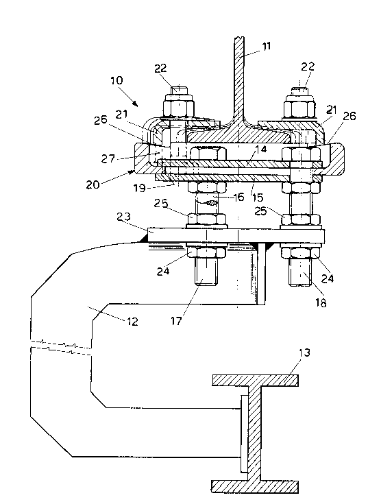
- figure 1 shows a schematic front cutaway view along the
lo line I-I of figure 3, of a device according to`the
invention;
- figure 2 shows a rear scrap view of the device of figure
l;
- figure 3 shows a top scrap view of the device of figure
1.
With reference to the figures, figure 1 shows an
adjustable supporting device 10, superiorly secured to an
I-beam 11 and from which inferiorly extends a generically
C-shaped supporting bracket 12, the lower end of which
being secured to a runway 13, for example a monorail along
which run known motor-powered conveyor carriages in an
industrial system, such as an assembly line.
As can also be clearly seen in figure 3, the adjustable
supporting device 10 comprises a casing or first element
20, secured superiorly to the lower edge of the beam by
means of fastening elements composed for example of a pair
of splice bars 21 clamped onto the flange of the beam by
means of pairs of tie bolts 22. As can be seen in figure

-- 2136~95
1, the splice bars can be advantageously L-shaped with
their lower end resting on upper surfaces of the casing
sloping downwards towards the beam. Moreover, the holes 27
for the passage of the bolts in the casing 20 are in the
form of an elongated slot crosswise to the beam. In this
way, as can be clearly seen in figure 1, the splice bars
can be adapted to different sized beams remaining with
their gripping ends substantially horizontal or otherwise
orientated to offer the best possible grip.
o The casing 2~ has a central hole which defines a
circumferential rim 19 disposed in a substantially
horizontal plane. A pair of circular plates 14, 15 are
disposed facing each other and interconnected by means of
three bolts 16, 17, 18 which move towards one another,
passing through the central hole, to grip the rim 1~
between them rotatingly according to a vertical axis.
The bolts 16, 17 18 have a shank extending downwards to
fit into respective holes in a second plate-shaped element
23 which is secured, for example by welding, to the upper
end of the bracket 12. The plate 23 is secured to the
shanks of the bolts by means of nuts 24 and lock nuts 25
to allow adjustment of the gap between plates 14, 15 and
plate 23.
The bracket 12 is thus able to rotate around a vertical
axis, by loosening the bolts securing the pair of plates,
and to ascend and descend by shifting the position of the
nuts 24 and lock nuts 25.
The nuts and lock nuts can also be shifted asymmetrically

-- -213649~
on the various shanks (that is to say, positioned at
different heights on the various shanks), so as to adjust
the slant of the bracket, which is useful for example to
compensate for lack of parallelism between the plane of
the beam and the runway.
At this point it will be clear that the intended scope is
achieved, by providing a device for adjusting the position
of the bracket which is easy to manufacture, sturdy and
permits ample adjustment, enabling continuous rotation by
o 360 .
The foregoing description of an embodiment applying the
innovative principles of this invention is obviously given
by way of example in order to illustrate such innovative
principles and should not therefore be understood as a
limitation to the sphere of the invention claimed herein.
~or example, although the figures show the pair of plates
connected to the bracket and the casing connected to the
beam suspension element, the opposite is obviously
possible. Moreover, the bolts used for adjusting the gap
can be provided in a larger number, for example, four.
Lastly, the gripping plates 14, 15 can also be made in the
form of circular rings which grip between their inner
edges the rim of the casing, directed radially outwards
instead of inwards.

Dessin représentatif
Une figure unique qui représente un dessin illustrant l'invention.
États administratifs

2024-08-01 : Dans le cadre de la transition vers les Brevets de nouvelle génération (BNG), la base de données sur les brevets canadiens (BDBC) contient désormais un Historique d'événement plus détaillé, qui reproduit le Journal des événements de notre nouvelle solution interne.

Veuillez noter que les événements débutant par « Inactive : » se réfèrent à des événements qui ne sont plus utilisés dans notre nouvelle solution interne.

Pour une meilleure compréhension de l'état de la demande ou brevet qui figure sur cette page, la rubrique Mise en garde , et les descriptions de Brevet , Historique d'événement , Taxes périodiques et Historique des paiements devraient être consultées.

Historique d'événement

Description Date
Inactive : CIB de MCD 2006-03-11
Le délai pour l'annulation est expiré 2002-11-25
Demande non rétablie avant l'échéance 2002-11-25
Réputée abandonnée - omission de répondre à un avis sur les taxes pour le maintien en état 2001-11-23
Inactive : Abandon.-RE+surtaxe impayées-Corr envoyée 2001-11-23
Demande publiée (accessible au public) 1996-05-24

Historique d'abandonnement

Date d'abandonnement Raison Date de rétablissement
2001-11-23

Taxes périodiques

Le dernier paiement a été reçu le 2000-11-02

Avis : Si le paiement en totalité n'a pas été reçu au plus tard à la date indiquée, une taxe supplémentaire peut être imposée, soit une des taxes suivantes :

  • taxe de rétablissement ;
  • taxe pour paiement en souffrance ; ou
  • taxe additionnelle pour le renversement d'une péremption réputée.

Les taxes sur les brevets sont ajustées au 1er janvier de chaque année. Les montants ci-dessus sont les montants actuels s'ils sont reçus au plus tard le 31 décembre de l'année en cours.
Veuillez vous référer à la page web des taxes sur les brevets de l'OPIC pour voir tous les montants actuels des taxes.

Historique des taxes

Type de taxes Anniversaire Échéance Date payée
TM (demande, 3e anniv.) - générale 03 1997-11-24 1997-11-05
TM (demande, 4e anniv.) - générale 04 1998-11-23 1998-10-28
TM (demande, 5e anniv.) - générale 05 1999-11-23 1999-10-26
TM (demande, 6e anniv.) - générale 06 2000-11-23 2000-11-02
Titulaires au dossier

Les titulaires actuels et antérieures au dossier sont affichés en ordre alphabétique.

Titulaires actuels au dossier
FATA AUTOMATION S.P.A.
Titulaires antérieures au dossier
GIORGIO DEANDREA
Les propriétaires antérieurs qui ne figurent pas dans la liste des « Propriétaires au dossier » apparaîtront dans d'autres documents au dossier.
Documents

Pour visionner les fichiers sélectionnés, entrer le code reCAPTCHA :


Pour visualiser une image, cliquer sur un lien dans la colonne description du document (Temporairement non-disponible). Pour télécharger l'image (les images), cliquer l'une ou plusieurs cases à cocher dans la première colonne et ensuite cliquer sur le bouton "Télécharger sélection en format PDF (archive Zip)" ou le bouton "Télécharger sélection (en un fichier PDF fusionné)".

Liste des documents de brevet publiés et non publiés sur la BDBC .

Si vous avez des difficultés à accéder au contenu, veuillez communiquer avec le Centre de services à la clientèle au 1-866-997-1936, ou envoyer un courriel au Centre de service à la clientèle de l'OPIC.

({010=Tous les documents, 020=Au moment du dépôt, 030=Au moment de la mise à la disponibilité du public, 040=À la délivrance, 050=Examen, 060=Correspondance reçue, 070=Divers, 080=Correspondance envoyée, 090=Paiement})


Description du
Document 
Date
(aaaa-mm-jj) 
Nombre de pages   Taille de l'image (Ko) 
Dessin représentatif 1999-08-03 1 25
Dessins 1996-05-23 2 57
Abrégé 1996-05-23 1 23
Description 1996-05-23 5 197
Revendications 1996-05-23 3 87
Rappel - requête d'examen 2001-07-23 1 118
Courtoisie - Lettre d'abandon (taxe de maintien en état) 2001-12-23 1 182
Courtoisie - Lettre d'abandon (requête d'examen) 2002-01-06 1 172
Taxes 1996-10-27 1 58