Sélection de la langue

Search

Sommaire du brevet 2138105 

Énoncé de désistement de responsabilité concernant l'information provenant de tiers

Une partie des informations de ce site Web a été fournie par des sources externes. Le gouvernement du Canada n'assume aucune responsabilité concernant la précision, l'actualité ou la fiabilité des informations fournies par les sources externes. Les utilisateurs qui désirent employer cette information devraient consulter directement la source des informations. Le contenu fourni par les sources externes n'est pas assujetti aux exigences sur les langues officielles, la protection des renseignements personnels et l'accessibilité.

Disponibilité de l'Abrégé et des Revendications

L'apparition de différences dans le texte et l'image des Revendications et de l'Abrégé dépend du moment auquel le document est publié. Les textes des Revendications et de l'Abrégé sont affichés :

  • lorsque la demande peut être examinée par le public;
  • lorsque le brevet est émis (délivrance).
(12) Brevet: (11) CA 2138105
(54) Titre français: METHODE ET DISPOSITIF POUR STABILISER LA LONGUEUR D'ONDE D'UN LASER
(54) Titre anglais: METHOD AND DEVICE FOR STABILIZATION OF THE EMISSION WAVELENGTH OF A LASER
Statut: Périmé et au-delà du délai pour l’annulation
Données bibliographiques
(51) Classification internationale des brevets (CIB):
  • H01S 03/13 (2006.01)
  • H01S 05/0687 (2006.01)
(72) Inventeurs :
  • GAMBINI, PIERO (Italie)
(73) Titulaires :
  • AGILENT TECHNOLOGIES, INC.
(71) Demandeurs :
  • AGILENT TECHNOLOGIES, INC. (Etats-Unis d'Amérique)
(74) Agent: SMART & BIGGAR LP
(74) Co-agent:
(45) Délivré: 1999-03-30
(22) Date de dépôt: 1994-12-14
(41) Mise à la disponibilité du public: 1995-06-17
Requête d'examen: 1994-12-14
Licence disponible: S.O.
Cédé au domaine public: S.O.
(25) Langue des documents déposés: Anglais

Traité de coopération en matière de brevets (PCT): Non

(30) Données de priorité de la demande:
Numéro de la demande Pays / territoire Date
TO 93 A 000 954 (Italie) 1993-12-16

Abrégés

Abrégé français

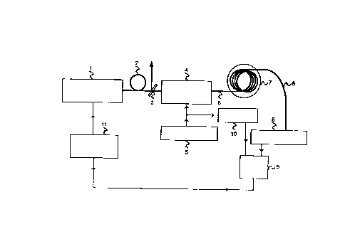
L'invention est constituée par une méthode et un dispositif de stabilisation qui asservissent la longueur d'onde d'émission d'un laser à une raie d'absorption d'un gaz. Le rayonnement émis par le laser est guidé jusqu'au détecteur dans l'environnement qui contient le gaz par un guide de lumière qui engendre un champ évanescent se propageant à l'extérieur de ce guide (figure 1).


Abrégé anglais


The method and the device obtain stabilization by
locking the emission wavelength of the laser to an
absorption line of a gas. The radiation emitted by the
laser is guided through the environment containing the gas
to the detector along an optical waveguide giving rise to
an evanescent field that propagates outside the waveguide
(Figure 1).

Revendications

Note : Les revendications sont présentées dans la langue officielle dans laquelle elles ont été soumises.


CLAIMS:
1. Method for absolute stabilization of the
emission wavelength of a semiconductor laser by locking
such wavelength to an absorption line of a gas, wherein the
radiation emitted by the laser is made to interact with the
gas while it is guided along an optical waveguide which
passes from the laser through an environment containing the
gas to a detector for detecting the radiation at the output
of the environment, whereby an error signal is obtained
from signals resulting from the detection, said optical
waveguide having such guiding characteristics as to give
rise to an evanescent field propagating outside the
waveguide itself in order to ensure interaction between the
radiation and the gas contained in the environment.
2. Method according to claim 1, wherein the such
waveguide is a "D" fibre.
3. Device for absolute stabilization of the
emission wavelength of a semiconductor laser, including
means for sending a radiation emitted by the laser into a
cell containing a gas which has an absorption line at a
wavelength near the nominal source wavelength, as well as
means for detecting the radiation at the output of cell and
obtaining an error signal from signals resulting from the
detection, wherein the sending means includes an optical
waveguide which passes for some of its length inside the
cell, is connected to the detection means and has such
guiding characteristics as to give rise to an evanescent
field propagating outside the waveguide itself, in order to
ensure interaction between the radiation and the gas
contained in the cell.
4. Device according to claim 3, wherein said
waveguide is a "D" fibre.

Description

Note : Les descriptions sont présentées dans la langue officielle dans laquelle elles ont été soumises.


- 2138105
The present invention refers to lasers, and, more particularly, regards a methodand a device for stabilization of the emission wavelength of a laser, such stabilization
being obtained by locking the emission wavelength to an absorption line of a gas.
Preferably, though not exclusively, the invention can be used for stabilization of
the emission wavelength of a semiconductor laser acting as source in an optical
communication system.
It is known that the laser emission wavelength is subjected to fluctuations and
that, consequently, lasers are associated to control circuits to stabilize such a
wavelength. In certain applications the stabilization must be absolute, i.e., independent
from the environment, so that the source remains fairly stable both in the short and
the long term and reproducibility of the emission wavelength is good. Such applications
include metrology (measurement of frequencies, lengths, etc.), wavelength division
multiplexing, optical communications, where a stable and accurate wavelength refe-
rence must exist in order to control transmitters at different locations or to ensure
correct identification of the various channels, etc.
In general, absolute 5t~bili~ation~ especially of semiconductor lasers, is obtained
by locking the emission wavelength of the laser to an absorption line of a gas having an
absorption spectrum with lines whose wavelength is near the emission wavelength of
the source (typically, in a neighbourhood of 1.5,um for optical communications appli-
cations). Several techniques have been proposed to implement the locking; two
examples are described by F. Bertinetto et al. in the papers: "Stabilization of the
Emission Frequency of 1.54 ~m DFB Laser Diodes to Hydrogen lodide", IEEE Photonics
Technology Letters, Vol. 4, No. 4, April 1993, and "Performance and Limitations of

:' 2138105
Laser Diodes Stabilized to the Sides of Molecular Absorption Lines of Ammonia",
Review of Scientific Instruments, 64 (8), August 1993, respectively for the locking
to the peak and to the sides of the line used.
In general, whatever technique is used, the radiation emitted by the laser is
adequately modulated and sent into a cell containing the gas, the output radiation is
detected, an error signal, representing the sign and the magnitude of the shift of the
actual laser wavelength relative to the line wavelength (and thus to the nominalemission wavelength), is derived through a feed-back loop from the detected signals,
and is fed to the laser control circuits. Transfer of radiation from the source to the cell
and from the cell to detector takes place in free space.
An inconvenience of known stabilization systems is that in many cases the
signal-to-noise ratio in ~he feed-back loop is relatively limited, also because of the
limited absorption of the gas used. Greater absorption can be obtained by using long
cells or multiple-path cells. It is not very practical, however, to consider cells longer
than a few tens of centimetres, especially in applications to field optical fibre systems.
Furthermore, in such applications, in which lasers are used with a fibre pig-tail for
waveguide connection between the source and the fibre which is the transmission line,
there is also the further drawback that guided propagation must be abandoned to have
radiation interaction w:th the gas, with possible troubles in alignment stability,
divergence of the beam over long paths, etc.
The purpose of the invention is to provide a method and a device for stabilization
of the above type, in which the inconveniences arising from free space propagation of
the radiation to be stabillzed are eliminated.
According to the invention~ a method is given in which the radiation to be
stabilized is made to interact with the gas while it is guided along an optical waveguide
traversing an environment containing the gas, the waveguide being such as to give rise
to an evanescent field also propagating outside the waveguide.
The device implementing the method includes means for sending the radiation
emitted by a laser into a cell containing a gas which has an absorption line at a
wavelength near the nominal source wavelength, as well as means for detecting the
radiation present at the cell output and for deriving an error signal from the signals
resulting from the detection; the sending means include an optical waveguide of which a
portion is located inside the cell and which is connected to the detection means and has
such guiding characteristics as to give rise to an evanescent field also propagating
around it, thus ensuring interaction between radiation and the gas contained in the cell.
Advantageously, the optical waveguide guide is a "D" fibre.
The invention will be now disclosed with reference to the enclosed drawings, in
which:

2138105
- Figure 1 is a schematic diagram of the device according to the invention;
- Figure 2 is a cross section of a D fibre, also showing the behaviour of the field
within the section.
Figure 1 shows the device according to the invention in the non limitative
example in which the signal from the source to be stabilized is phase-modulated and
the locking is done with respect to the peak of the absorption line, as described in the
first of the two above mentioned papers of F. Bertinetto et al. The invention is at any
rate independent of the particular locking technique used. In the figure, thick lines
represent optical waveguides and thin ones electrical connections.
This being given, the signal emitted by source 1, for instance a semiconductor
laser already associated with a fibre pig-tail, is sent to a fibre stub 2. Through power
splitting device 3 the signal is split into two parts, one part being the useful signal and
the other being used for stabilization. The latter part is sent to an optical phase
modulator 4 driven by a radio-frequency signal provided by generator 5. The phase-
modulated signal is collected by a fibre 6 passing, for some of its length, inside a cell 7
filled with a gas having absorption lines which can be used for wavelength stabilization
of source 1.
Fibre 6 enters or leaves cell 7 through apertures sealed with, for example,
epoxy resin. Outside of cell 7, fibre 6 terminates on a photo- detector 8, whose output
is connected in turn to mixer 9 which also receives signals from generator 5. A phase-
shifting device 10 between generator 5 and mixer 9 sets the correct phase
relationship between the modulating signal and the cell output signal. The mixer output
is a signal whose amplitude and sign depend on the shift between the actual emission
wavelength of laser 1 and the nominal wavelength such signal, adequately filtered in
loop filter 11, drives control circuits of laser 1 (integrated into the same block
representing the source). Depending on the type of laser, the signal output by filter 11
will adjust the laser injection current, or the temperature, or the position of a
mirror, etc.
Fibre 6 is advantageously a "D" fibre. A "D" fibre owes its name to the shape ofits cross section. As it can be seen from Figure 2, cladding 12 of the fibre has a flat
part, obtained by axially cutting the preform, and the core comes very close to the flat
part. The electromagnetic field thus presents tails (evanescent field) propagating in
the environment around the fibre, which environment can thus affect a signal
transmitted along the fibre itself. Therefore, by using such fibres, the interaction is
obtained between the radiation emitted by source 1 and the gas contained in cell 7, as
required for locking to an absorption line, even though propagation of the radiation is
guided within the cell.
The system herein described eliminates the above mentioned inconveniences.

- 21~8105
Indeed, a fairly long fibre stub can be placed inside a cell 7 even of reduced size, so
that there is a long region of interaction between radiation emitted by laser 1 and the
gas in a limited room. Moreover, thanks to the fact that the radiation to be stabilized is
guided from the source up to the detector, no optical misalignment occurs, and
optimum mechanical stability of the device is ensured.
It is evident that the above description is merely a non limitative example, andthat variants and modifications are possible which are within the scope of the
invention .

Dessin représentatif
Une figure unique qui représente un dessin illustrant l'invention.
États administratifs

2024-08-01 : Dans le cadre de la transition vers les Brevets de nouvelle génération (BNG), la base de données sur les brevets canadiens (BDBC) contient désormais un Historique d'événement plus détaillé, qui reproduit le Journal des événements de notre nouvelle solution interne.

Veuillez noter que les événements débutant par « Inactive : » se réfèrent à des événements qui ne sont plus utilisés dans notre nouvelle solution interne.

Pour une meilleure compréhension de l'état de la demande ou brevet qui figure sur cette page, la rubrique Mise en garde , et les descriptions de Brevet , Historique d'événement , Taxes périodiques et Historique des paiements devraient être consultées.

Historique d'événement

Description Date
Inactive : CIB expirée 2020-01-01
Le délai pour l'annulation est expiré 2008-12-15
Lettre envoyée 2007-12-14
Inactive : CIB de MCD 2006-03-11
Lettre envoyée 2001-06-07
Lettre envoyée 2000-05-12
Inactive : Transferts multiples 2000-04-11
Accordé par délivrance 1999-03-30
Préoctroi 1998-12-17
Inactive : Taxe finale reçue 1998-12-17
Lettre envoyée 1998-10-26
Un avis d'acceptation est envoyé 1998-10-26
Inactive : Approuvée aux fins d'acceptation (AFA) 1998-09-17
Modification reçue - modification volontaire 1998-06-15
Inactive : Renseign. sur l'état - Complets dès date d'ent. journ. 1998-02-18
Inactive : Dem. traitée sur TS dès date d'ent. journal 1998-02-18
Inactive : Dem. de l'examinateur par.30(2) Règles 1998-02-13
Demande publiée (accessible au public) 1995-06-17
Exigences pour une requête d'examen - jugée conforme 1994-12-14
Toutes les exigences pour l'examen - jugée conforme 1994-12-14

Historique d'abandonnement

Il n'y a pas d'historique d'abandonnement

Taxes périodiques

Le dernier paiement a été reçu le 1998-11-16

Avis : Si le paiement en totalité n'a pas été reçu au plus tard à la date indiquée, une taxe supplémentaire peut être imposée, soit une des taxes suivantes :

  • taxe de rétablissement ;
  • taxe pour paiement en souffrance ; ou
  • taxe additionnelle pour le renversement d'une péremption réputée.

Les taxes sur les brevets sont ajustées au 1er janvier de chaque année. Les montants ci-dessus sont les montants actuels s'ils sont reçus au plus tard le 31 décembre de l'année en cours.
Veuillez vous référer à la page web des taxes sur les brevets de l'OPIC pour voir tous les montants actuels des taxes.

Titulaires au dossier

Les titulaires actuels et antérieures au dossier sont affichés en ordre alphabétique.

Titulaires actuels au dossier
AGILENT TECHNOLOGIES, INC.
Titulaires antérieures au dossier
PIERO GAMBINI
Les propriétaires antérieurs qui ne figurent pas dans la liste des « Propriétaires au dossier » apparaîtront dans d'autres documents au dossier.
Documents

Pour visionner les fichiers sélectionnés, entrer le code reCAPTCHA :


Pour visualiser une image, cliquer sur un lien dans la colonne description du document. Pour télécharger l'image (les images), cliquer l'une ou plusieurs cases à cocher dans la première colonne et ensuite cliquer sur le bouton "Télécharger sélection en format PDF (archive Zip)" ou le bouton "Télécharger sélection (en un fichier PDF fusionné)".

Liste des documents de brevet publiés et non publiés sur la BDBC .

Si vous avez des difficultés à accéder au contenu, veuillez communiquer avec le Centre de services à la clientèle au 1-866-997-1936, ou envoyer un courriel au Centre de service à la clientèle de l'OPIC.


Description du
Document 
Date
(aaaa-mm-jj) 
Nombre de pages   Taille de l'image (Ko) 
Dessin représentatif 1999-03-22 1 4
Abrégé 1995-06-16 1 11
Description 1995-06-16 4 174
Revendications 1995-06-16 1 42
Dessins 1995-06-16 1 8
Revendications 1998-06-14 1 43
Avis du commissaire - Demande jugée acceptable 1998-10-25 1 164
Avis concernant la taxe de maintien 2008-01-27 1 174
Correspondance 1998-12-16 1 38
Correspondance 2000-05-11 1 23
Taxes 1997-10-15 1 32
Taxes 1998-11-15 1 31
Taxes 1999-11-17 1 26
Taxes 1996-10-14 1 38