Sélection de la langue

Search

Sommaire du brevet 2138293 

Énoncé de désistement de responsabilité concernant l'information provenant de tiers

Une partie des informations de ce site Web a été fournie par des sources externes. Le gouvernement du Canada n'assume aucune responsabilité concernant la précision, l'actualité ou la fiabilité des informations fournies par les sources externes. Les utilisateurs qui désirent employer cette information devraient consulter directement la source des informations. Le contenu fourni par les sources externes n'est pas assujetti aux exigences sur les langues officielles, la protection des renseignements personnels et l'accessibilité.

Disponibilité de l'Abrégé et des Revendications

L'apparition de différences dans le texte et l'image des Revendications et de l'Abrégé dépend du moment auquel le document est publié. Les textes des Revendications et de l'Abrégé sont affichés :

  • lorsque la demande peut être examinée par le public;
  • lorsque le brevet est émis (délivrance).
(12) Demande de brevet: (11) CA 2138293
(54) Titre français: CONNECTEUR ELECTRIQUE
(54) Titre anglais: ELECTRICAL CONNECTOR
Statut: Réputée abandonnée et au-delà du délai pour le rétablissement - en attente de la réponse à l’avis de communication rejetée
Données bibliographiques
(51) Classification internationale des brevets (CIB):
  • H01R 13/115 (2006.01)
  • H01R 13/187 (2006.01)
(72) Inventeurs :
  • HOPF, GUSTAV (Allemagne)
(73) Titulaires :
  • FRAMATOME CONNECTORS INTERNATIONAL
(71) Demandeurs :
  • FRAMATOME CONNECTORS INTERNATIONAL (France)
(74) Agent: SMART & BIGGAR LP
(74) Co-agent:
(45) Délivré:
(86) Date de dépôt PCT: 1993-12-09
(87) Mise à la disponibilité du public: 1994-07-07
Licence disponible: S.O.
Cédé au domaine public: S.O.
(25) Langue des documents déposés: Anglais

Traité de coopération en matière de brevets (PCT): Oui
(86) Numéro de la demande PCT: PCT/EP1993/003460
(87) Numéro de publication internationale PCT: WO 1994015380
(85) Entrée nationale: 1994-12-15

(30) Données de priorité de la demande:
Numéro de la demande Pays / territoire Date
P 42 42 972.2 (Allemagne) 1992-12-18

Abrégés

Abrégé anglais


For an electrical connector with a socket contact, formed by means of a sleeve body with attachment means for the connecting leads,
for the displaceable reception of a contact pin, where a segmented cage, which can rest pressingly against the pin contact, is housed in the
sleeve body so as to be fixed axially in position, the segmented cage (8) is formed by means of a cylindrically rolled flat sheet metal blank
(9), whose longitudinal outer strips (10) are connected together by means of a number of ribs (11), which extend side by side separated
from each other, the chamfered contact tabs (13), which are opposite one another at the longitudinal outer strips (10), project into the free
spaces (12) between the ribs (11), whereby a first segment (13') of said contact tab curves in the direction of the central longitudinal axis
of the segmented cage (8) and whereby a second segment (13"), formed by means of the free ends, is bent back and is shorter than half
the length of the segmented cage (8), in order to ensure a reliable and effective contact.

Revendications

Note : Les revendications sont présentées dans la langue officielle dans laquelle elles ont été soumises.


Patent Claims
1. Electrical connector with a socket contact, formed by means of
a sleeve body with attachment means for the connecting leads, for
the displaceable reception of a contact pin, where a segmented
cage, which can rest pressingly against the pin contact, is
housed in the sleeve body so as to be fixed axially in position,
characterized in that
the segmented cage (8) is formed by means of a cylindrically
rolled flat sheet metal blank (9), whose longitudinal outer
strips (10) are connected together by means of a number of ribs
(11), which extend side by side separated from each other, and
where chamfered contact tabs (13), which are opposite one another
at the longitudinal outer strips (10), project into the free
spaces (12) between the ribs (1), whereby a first segment (13')
of said contact tab curves in the direction of the central
longitudinal axis of the segmented cage (8) and whereby a second
segment (13"), formed by means of the free ends, is bent back
and is shorter than half the length of the segmented cage (8).
2. Connector as claimed in claim 1, characterized in that
the ribs (11) of the segmented cage (8) exhibit one depression
(14) each and in that the depressions (14) form guide and support
elements for the contact pin (15).
3. Connector as claimed in claim 2, characterized in that
the depressions (14) in the ribs (11) of the segmented cage (8)
are useful as stops in order to fix axially the segmented cage
(8) in position in the sleeve body (7).

4. Connector as claimed in claim 1 and 2, characterized in that
the sleeve body (7) for axial fixation in the connector housing
(5) reaches with a bend-out (18) into a recess (19) of the
connector housing (5).
5. Connector as claimed in claim 4, characterized in that
the recess (19) is formed by means of an annular groove.
6. Connector as claimed in claim 1, characterized in that
a segment (7') of the sleeve body (7) projects at the plug-in
end (16) beyond the segmented cage (18), and in that the segment
(7') is bent down toward the plug-in direction and relative to
the central longitudinal axis and serves as a supporting or
aligning element for the contact pin (15).

Description

Note : Les descriptions sont présentées dans la langue officielle dans laquelle elles ont été soumises.

WO94/15380 213 8 2 9 3 PCT~3/03~0
_
ELECTRICAL CONNECTOR
The invention relates to an electrical connector with a socket
contact, formed by means of a sleeve body with attachment means
for the connecting leads, for the displaceable reception of a
contact pin, where a segmented cage, which can rest pressingly
against the pin contact, is housed in the sleeve body so as to
be fixed axially in position.
Sleeve-shaped socket contacts for the plugable reception of
contact pins are known in particular for circular connectors
(DE application P 35 31 845.7). To improve the contact between
socket contact and contact pin, the socket contacts are provided
with a segmented cage, which makes contact with the contact pin
so as to be frictionally engaged. The front outer strips of the
segmented cage exhibit ribs that are bent inwardly. Apart from
the fact that a relatively significant work of deformation must
be exerted on the ribs of the segmented cage during plugging
operations, the ribs also afford only small contact areas,
resulting in unreliable contacts.
The object of the invention is to make the contacting of an
electrical connector of the aforementioned class more reliable
and more effective.
The invention solves this problem by forming the segmented cage
by means of a cylindrically rolled flat sheet metal blank, whose
longitudinal outer strips are connected together by means of a
number of ribs, which extend side by side separated from each

WO94/15380 ~ PCT~3/03~0
?,~3~g 2
other, and where chamfered contact tabs, which are opposite one
another at the longitudinal outer strips, project into the free
spaces between the ribs, whereby a first segment of said contact
tab curves in the direction of the central longitudinal axis of
the segmented cage and whereby a second segment, formed by means
of the free ends, is bent back and is shorter than half the
length of the segmented cage. In the case of a connector designed
thus, a number of contact tabs come to rest simultaneously with
the contact pins in order to make a contact; said contact tabs
can be bent down separately independently of each other and can
be applied by pressing to the contact pin so as to engage
frictionally. Thus, reliable contact transitions and ease of
plugging are guaranteed especially when the contact pin is
misaligned or tilted.
The design of the connector provides that the ribs of the
segmented cage exhibit one depression each and that the
depressions form guide and support elements of the contact pin.
Thus, a central insertion of the contact pin into the socket
contact is guaranteed, whereby the contact tabs make contact
simultaneously with the contact pin with essentially identical
deflections. Furthermore, it is provided that depressions are
formed, for example, in the ribs of the segmented cage, which are
employed as stops to fix axially the same in position in the
sleeve body. It is obvious that the segmented cage can be axially
fixed in position in the sleeve body in a different manner, e.g.,
by attaching extensions, shoulders or the like to the sleeve
body.
Furthermore, measures for axial fixation of the sleeve body in
the connector housing are provided by the fact that the sleeve
body reaches, e.g., with a bend-out into a recess of the
connector housing. Preferably the recess can be formed by means
of an annular groove. Finally, other guide measures for the
contact pin during the contact period or plugging operation can

WO94/15380 2 I 3 ~ 2 9 3 PCT~3/03~0
be achieved, if a segment of the sleeve body projects at the
plug-in end beyond the segmented cage, whereby the segment is
bent down toward the plug-in direction and relative to the
central longitudinal axis of the segmented cage and serves as an
additional supporting or aligning element for the contact pin.
Thus, with the bend the contact pin can be pre-aligned during the
plugging operation; and when the contact pin is subsequently
actively connected to the depressions, the conditions for a
reliable alignment and guide of the contact pin in the segmented
cage of the socket contact are created.
The invention is explained with reference to an embodiment in the
drawings.
Figure l is a side view of a known segmented cage.
Figure 2 is a sectional view of a segmented cage of Figure l.
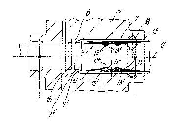
Figure 3 is a sectional view of a connector according to one
embodiment.
Figure 4 is a sectional view of another connector.
Figures 5, 6 and 7 depict roll downed segmented cages of
different diameter sizes; and
Figure 8 is a sectional view along the line VIII-VIII of Figure
5.
The known segmented cage l shown in Figures l and 2 exhibits
front outer strips 2 and 3, which are connected together by means
of ribs 4. The ribs 4 are curved in the direction of the central
longitudinal axis of the segmented cage l in order to achieve a
prestress and thus to enable them to rest pressingly against the
contact pin when a contact pin (not illustrated) is inserted. If

W094/15380 ~3 ~ ~ ~ 3 PCT~3103~0
the contact pin is tilted or inaccurately plugged in or when the
diameter sizes differ, the ribs 4 afford, however, only
inadequate or unreliable contact.
Figure 3 depicts a connector, whose plug housing 5 exhibits a
bore 6, which serves to receive a sleeve body 7. The illustrated
sleeve body 7 is provided with crimp extensions (not illustrated)
to fix in position the electrical leads or their insulation. The
sleeve body 7 is fixed in position in the plug housing 5, e.g. by
means of a bend-out 18 and can be made of any arbitrary material,
e.g. also a ferrous material, an alloyed material or the like and
can thus be fabricated relatively economically. A segmented cage
8, which is formed by means of a flat blank 9, which is shown in
Figures 5 to 8 for different diameter sizes and is made of a
material exhibiting high electrical conductivity, is put into the
sleeve body 7. As evident from Figures 5 to 8, the blank is
provided with two longitudinal outer strips 10, which are
connected together by means of a number of ribs 11. Contact tabs
13, which are opposite one another at the longitudinal outer
strips (10) and which extend in the flat blank appro~imately as
far as half the width of the segmented cage 8, are chamfered in
the regions of the free spaces 12 between the ribs 11. In
addition, the ribs 11 exhibit depressions 14. The flat blanks of
Figures 5 to 8 can be bent apart in the shape of a cylinder
(Figures 2 and 3), whereby now the contact tabs 13 extend
approximately as far as half the length of the segmented cage.
In addition, a first segment 13' of the contact tabs 13 is bent
inwardly and a second segment 13'', formed by the free ends, is
bent back outwardly. With the arched segments 13''' obtained
thus, the contact tabs 13 come to rest pressingly against a
contact pin 15. Furthermore, the contact tabs 13 enable the
contact pin to be plugged in without any hindrance. The
depressions 14 serve as supporting and guide elements for the
contact pin 15, thus guaranteeing that the contact tabs 13 rest
uniformly against the contact pin 15 and thus guaranteeing a

WO94/15380 213 8 2 9 3 PCT~3/03460
reliable contact. Furthermore, the end of the sleeve body 7 that
has approached the insertion opening 16 is pulled forward with a
subsegment 7' over the segmented cage 8; and this subsegment 7'
is bent so as to slope inwardly in the direction of the central
longitudinal axis 17. Thus, the free outer edge 7'' of the
subsegment 7' acts as an additional guide body, in particular at
the start of the plugging operation for the contact pin 15.
It is self-evident that an arbitrary number of ribs ll and
contact tabs 13 for the segmented cage 8 can be chosen. Even the
substantially trapezoidal shape of the contact tabs 13 selected
for the embodiment can vary.

Dessin représentatif
Une figure unique qui représente un dessin illustrant l'invention.
États administratifs

2024-08-01 : Dans le cadre de la transition vers les Brevets de nouvelle génération (BNG), la base de données sur les brevets canadiens (BDBC) contient désormais un Historique d'événement plus détaillé, qui reproduit le Journal des événements de notre nouvelle solution interne.

Veuillez noter que les événements débutant par « Inactive : » se réfèrent à des événements qui ne sont plus utilisés dans notre nouvelle solution interne.

Pour une meilleure compréhension de l'état de la demande ou brevet qui figure sur cette page, la rubrique Mise en garde , et les descriptions de Brevet , Historique d'événement , Taxes périodiques et Historique des paiements devraient être consultées.

Historique d'événement

Description Date
Inactive : CIB de MCD 2006-03-11
Le délai pour l'annulation est expiré 1996-06-09
Demande non rétablie avant l'échéance 1996-06-09
Réputée abandonnée - omission de répondre à un avis sur les taxes pour le maintien en état 1995-12-11
Inactive : Demande ad hoc documentée 1995-12-11
Demande publiée (accessible au public) 1994-07-07

Historique d'abandonnement

Date d'abandonnement Raison Date de rétablissement
1995-12-11
Titulaires au dossier

Les titulaires actuels et antérieures au dossier sont affichés en ordre alphabétique.

Titulaires actuels au dossier
FRAMATOME CONNECTORS INTERNATIONAL
Titulaires antérieures au dossier
GUSTAV HOPF
Les propriétaires antérieurs qui ne figurent pas dans la liste des « Propriétaires au dossier » apparaîtront dans d'autres documents au dossier.
Documents

Pour visionner les fichiers sélectionnés, entrer le code reCAPTCHA :


Pour visualiser une image, cliquer sur un lien dans la colonne description du document. Pour télécharger l'image (les images), cliquer l'une ou plusieurs cases à cocher dans la première colonne et ensuite cliquer sur le bouton "Télécharger sélection en format PDF (archive Zip)" ou le bouton "Télécharger sélection (en un fichier PDF fusionné)".

Liste des documents de brevet publiés et non publiés sur la BDBC .

Si vous avez des difficultés à accéder au contenu, veuillez communiquer avec le Centre de services à la clientèle au 1-866-997-1936, ou envoyer un courriel au Centre de service à la clientèle de l'OPIC.


Description du
Document 
Date
(aaaa-mm-jj) 
Nombre de pages   Taille de l'image (Ko) 
Description 1994-07-07 5 197
Abrégé 1994-07-07 1 51
Page couverture 1995-08-15 1 15
Revendications 1994-07-07 2 58
Dessins 1994-07-07 2 47
Dessin représentatif 1998-07-28 1 9
Rapport d'examen préliminaire international 1994-12-15 9 266