Sélection de la langue

Search

Sommaire du brevet 2138795 

Énoncé de désistement de responsabilité concernant l'information provenant de tiers

Une partie des informations de ce site Web a été fournie par des sources externes. Le gouvernement du Canada n'assume aucune responsabilité concernant la précision, l'actualité ou la fiabilité des informations fournies par les sources externes. Les utilisateurs qui désirent employer cette information devraient consulter directement la source des informations. Le contenu fourni par les sources externes n'est pas assujetti aux exigences sur les langues officielles, la protection des renseignements personnels et l'accessibilité.

Disponibilité de l'Abrégé et des Revendications

L'apparition de différences dans le texte et l'image des Revendications et de l'Abrégé dépend du moment auquel le document est publié. Les textes des Revendications et de l'Abrégé sont affichés :

  • lorsque la demande peut être examinée par le public;
  • lorsque le brevet est émis (délivrance).
(12) Demande de brevet: (11) CA 2138795
(54) Titre français: RONDELLE A ACTION RAPIDE, POUR POTEAU D'ETAYAGE
(54) Titre anglais: QUICK RELEASE WASHER FOR A SHORING POST
Statut: Réputée abandonnée et au-delà du délai pour le rétablissement - en attente de la réponse à l’avis de communication rejetée
Données bibliographiques
Abrégés

Abrégé anglais

2138795 9425705 PCTABS00034
A shoring post (10) comprises a support post (12) slidingly
engaging a telescoping sleeve member (14) and a screw device for
incrementally adjusting the length of the shoring post. The
telescoping member (14) having a plurality of pairs of diametrically
opposed holes spaced therealong. A pin member (26) for inserting
through a pair of the diametrically opposed holes of the telescoping
member to releasably extend the shoring post. A quick release
washer (28) for quickly reducing an overall length of the shoring
post. The washer (28) comprising a ring portion having a pair of
diametrically opposed cam lobes (30). The lobes having an inclined
surface (32), a cradling surface (34) and a stop. The washer (28)
is mounted between the pin (26) and the support post (12). The
washer has a load transfer position wherein the pin is cradled
between the cradling surface and the stop surface and a quick release
position whereby as the washer is rotated relative to the pin,
the pin travels along the inclined surface reducing the overall
length of the shoring post.

Revendications

Note : Les revendications sont présentées dans la langue officielle dans laquelle elles ont été soumises.


WO 94/25705 PCT/CA94/00197
- 8 -
I claim:
1. A shoring post comprising a support post slidingly engaging a
telescoping sleeve member, a screw means for incrementally adjusting the length of
said shoring post, said telescoping member having a plurality of pairs of diametrically
opposed holes spaced therealong, a pin member for inserting through a pair of said
diametrically opposed holes of said telescoping member to releasably extend said
shoring post, wherein the improvement comprises a quick release washer for quickly
reducing an overall length of said shoring post, said washer comprising a ring portion
having a pair of diametrically opposed cam lobes, said lobes having an inclined
surface and a cradling surface, said washer mounted between said pin and said
support post, said washer is rotatable between a load transfer position wherein said
pin is cradled on the cradling surface and a quick release position wherein as said
washer is rotated relative to the pin, the pin travels along the inclined surface
reducing the overall length of the shoring post.
2. A shoring post as claimed in claim 1 wherein said washer includes
abutments means for receiving hammer blows for urging said washer to rotate
relative to said pin.
3. A shoring post as claimed in claim 2 wherein said screw means is a nut
member threadably mounted on one end of said support post and said washer abuts
said nut member.
4. A quick release washer for a shoring post, said shoring post comprising
a support post slidingly engaging a telescoping sleeve member, a screw means for
WO 94/25705 PCT/CA94/00197
- 9 -
incrementally extending said shoring post, said telescoping member ha ring a plurality
of pairs of diametrically opposed holes spaced therealong, a pin member for inserting
through a pair of said diametrically opposed holes of said telescoping member to
releasably extend said shoring post, said washer comprising
a ring portion having a pair of diametrically opposed cam lobes, said
lobes having an inclined surface and a cradling surface, said washer mounted between
said pin and said support post, said washer is rotatable between a load transfer
position wherein said pin rests on the cradling surface and a quick release position
wherein as said washer is rotated relative to the pin, the pin travels along the inclined
surface retracting the shoring post.
5. A washer as claimed in claim 4 wherein said washer includes abutments
means for receiving hammer blows to cause said washer to rotate relative to said pin.
6. A washer as claimed in claim 5 wherein said cam lobes include a stop
surface for restricting the direction of the relative rotation of the washer.
7. A washer as claimed in claim 6 wherein said washer moves from the
cradle position to the quick release position upon less than one quarter rotation of
said washer.

Description

Note : Les descriptions sont présentées dans la langue officielle dans laquelle elles ont été soumises.

~ ~ ;i wo 94,25705 ~ 2 i 3 8 7 9 5 PCTICA94/00197
- 1 -
QUICK RELEASE WASEER FOR A SHORIN& POST
Field of Invention
This invention relates to a device for quickly releasing pressure being
exerted on a shoring post andJor similar support equipment where it is desirable to
5 easily loosen a mlt of the shoring post while it is supporting a compressive load.
Baclcground of the Invention
In the construction industry, shoring is widely used to support forms for
concrete construction of buildings, bridges and other structures. Flying forms such
as those described in a co-pending United States application, serial no. 07/6S3,S49,
10 ~lled February 11, 1991, can be used to construct buildings using a ~ying ~o~
method. Other types of support structures are described in an earlier U.S. patent no.
4,470,574. Once the concrete has initially cured, the support structure is removed
and advanced to other locations. However, the concrete has not yet fully cured and
ablP to support its own weight load and the additional loads of additional shoring and
15 other equipment and the new concrete being poured as upper ~oors. Accordingly
shoring posts are used to support the curing concrete structure until it has sufficiently
cured.
Shoring posts are well known in the art. Shoring posts of the prior art
indlide U.S. patent nos. 3,870,268 and 3,847,340. Generally shoring posts comp~ise
20 a telescoping sleeve slidably mounted in a support post. The sleeve has a plurality
of aligned diametncally extending holes through which a pin can be inserted. The
length of the shoring post can be roughly fixed by inserting the pin through the hole

WO 94/25705 , ^ , , E'CT/CA94100197 ~
2l38795
nearest the desired height. A screw thread is mounted on the post or machined into
the outer surface of the post and a threaded nut or handle is advanced to extend the
post until it fully supports the load.
Shoring posts of the prior art per~orm reasonably adequately. However
5 at times, unloading the shoring posts can be di~icult. Since ~he shoring post is under
a compressive load, especially if the shoring post is used to support forms in which
concrete is poured, the adjusting nuts on the shonng post are often difficult to
unscrew. Hammers are often used to Imscrew the nut of the screw jack. Since the
screw thread is normally adapted for incremental extensions of the shonng post
10 between adjusting holes, unscrewing the post nut in this manner is time consuming.
In U.S. patent no. 3,870,268, a release slide is described. I'he release
s~de has a thicker portion and a thinner portion which extends diametrically through
holes between the lower tube and the telescoping tub . The slide is urged across from
the thicker portion to the thinner portion reducing the length of the shoring post
15 releasing the pressure acting thereon. The holes through which the release slide acts
is often damaged during normal usage. The release slide normally has a circular
cross-section. This geometry results in the pressure loads to be transmitted ~om the
telescoping tube to the outside lower tube through two diametrically opposed points.
The holes in the telescoping tube and the lower tube often become deformed out of
20 shape dramadcrlly reducing the life of the shoring post.
, .
~'
'
,~ .

WO 94125705 ` 213 8 7 9 5 PCT/CA94/00197
- 3 -
Summarv of the Tnvention
The disadvantages of the prior art may be overcome by providing a
device for quickly releasing the loading of a shoring post yet is capable of transmitting
and supporting the pressure load acting on the shonng post without damage.
S According to one aspect of the invention, there is provided a shormg
post comprising a support post slidingly engaging a telescoping member and a screw
device for incrementally adjusting the length of ~he shoring post. The telescoping
member having a plurality of pairs of diametrically opposed holes spaced therealong.
A pin member for inserting through a pair of the diarnetrically opposed holes of the
telescoping member to adjust and releasably extend the shoring post. A quick release
washer for quickly reducmg an overall length of the shoring post. The washer
comprises a ring portion having a pair of diametrically opposed cam lobes. The lobes
having an inclined surface, a cradling surface and a stop. Ihe washer is mountedbe~veen the pin member and the outer support po~tion of the shore post. The
washer has a load transfer position wherein the pin is cradled between the cradling
surface and the stop sur~ace and a quick release position whereby as the washer is
rotated relative to the pin, the pin travels along the inclined surface reducing the
overall length of the shoring post.
Descnption of the; Drawin~s ~
In Figures which illustrate embodiments of the inveneion,
Figure 1 is a front elevational view of the shonng post of the
pres*nt invention;
,~

;
WO 94ns705 ~ PCT/CA94/00197
.2~879s
.:
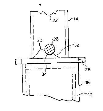
Figure 2 is a side elevational view of the pin, collar and washer of
the inven~ion of Figure 1;
Figure 3 is a bottom view of an end~plate of the shoring post of
the invention of Figure 1;
Figure 4 is a side elevational vlew of the pin, collar and washer of
the invention of Figure 1;
Figure S is a top p~an view of the washer of Figure 1; and
Figure 6 is a perspective view of the washer of Figure 1.
Detailed Description of the Invention
10The shoring post of the present invention is generally illustrated as 10
in Figure 1. The shonng post comprises a support post 12 and a telescop~g tube 14.
At the upper end of support post 12 is an adjustment handle 16.
Handle 16 has a tubular body having an internal thread and a pair of U-shaped
handles 18. Adjustment handle 16 threadably engages~ screw thread on the outside
15 surface at one end support post 12. Rotation of the handle 16 will ad~ance th~
- handle along the screw thread of suppor~t post 12. The lower end of support post 12
has plate 20 welded thereto.
Shoring post 10 is a cylindrical telescoping tube having a circular cross
section in the preferred `embodiment. Other-cross sectional shapes of tubing may be
20 used with satisfactory results.
TelescopLng sleeve 14 has an ou~side diameter less than the inside
diameter of suppon post 12 for telescoprllg within suppon post 12 m a slidi~g fit.
.
'

213879S
WO 94/25705 - l?CT/CA94/00197
S _ , . .
Sleeve 14 has a plurality of diametrically opposed holes 22 spaced along the a~al
length of the sleeve. An end plate 20 is welded to the upper end of sleeve 14.
Washer 28 rests between pin 26 and adjustment handle 16. Pin 26 exsends through
the pair of holes 22 in telescoping sleeve 14. Pin is preferable sh~ped as illus~rated
S in Figure 2 which is a type of pin which can be easily inserted through the holes but
is prevented from accidentally falling out.
Referring to Figure 5, washer 28 is generally a ring ha~ring at least a
pair of diametrically opposed cam lobes 3Q. Each cam lobe has an inclirled wedge
surface 32, a cradling surface 34 and a stop 36 as illustrated in Figures 4 and 5.
10 Ex~ending from the nng, washer 28 has a pair of diametrically opposed abutment
surfaces 38. Cradling surface 34 is contoured to receive and cradle pin 26. Stop 36
pre~ents washer 36 from rota~ing in one direction relathe to pin 26 when pin 26 is
cradled in cradling surface 34. The dis~ance ~om cradling surface 34 to the ring
portion of washer 28 is the dif~erence in length which4~he shoring post 10 will retract.
15 Accordingly, for greaeer retraction, this distance can be varied on difEerent sized
washers by va~ing the height of cradling surface 34. Additionally, the angle of the
inclined wedge surface 32 will determine the rate of detraction as the washer rotates.
The more abrupt the re~raction, the steeper the incline.
The face of washer 28 opposite the face having lobes 30 is gene~ally
20 planar for abutting with an end of a support post 12.
To assemble, washer 28 is presented to telescop~ng sleeve 14. The
lower end of sleeve 14 is presented into support post 12 in a sliding fit.

WO 94/25705 .;; ; ' PCT/CA94/00197
- 6 - 7,~
2~38lgs
In use, the shoring post 10 is extended until it appro~amately equals the
desired length between a suppo~ surface 40 and a supported surface 42. Pin 26 is
inserted through the nearest pair of opposed holes 22. Washer 28 is rotated until
cradling sur~ace 34 is immediately below pin 26. Adjustment handle 16 is rotated
S ex~ending the overall length of shoring pos~ 10 until the shor~ng post fully supports
the load of the supported surface. In this load transfer position, the load is
transmitted ~om the telescoping sleeve 14, through the pin 26 to the cam lobe 30 to
handle 16 and finally to the support post 12.
To quickly release the shoring post 10, a hammer contacts one of
10 abutme~t suraces 38. Washer 28 is urged in a direction relatively opposite the stop
36 causing the pin to travel relatively down the inclined surface 327 reducing the
overall length of the shosing post 10 and reducing the pressure acting on the handle
16 allowing the hand]e to be easily turned and unscrewed reducing length of shoril~g
post 10 which allows telescoping sleeve 14 to retra~ into support post 12.
In the pre~erred embodiment, the circumferential length of cam lobes
30 is less than one quarter of the circumferential distance of the ring of washer 28.
In this manner less than one quarter rotation of the washer is necessary to reduce the
overall length of the shoring post 10.
In other embodiments, handle 16 could easily be replaced with a nut
20 threadably enga~ing the support post 12. Other methods of fLne adjustment could
be used with the present invention, including the use of a collar hav~ng a hinged
.. ,

~g ~ ,
WO 94/25705 ` 213 8 7 9 5 PCT/CA94/00197
. . . ~, ,. . ~
handle threadable engaging a threaded support tube wherein the pin supporting the
telescoping member extends through a vertical slot.
Although the disclosure describes and illustrates the preferred
embodiments of the invention, it is understood that the invention is not limited to
5 these particular embodiments. Many variations and modifications will now occur to
those skilled in the art. For definition of the invention, reference is made to the
appen~ed claims.

Dessin représentatif
Une figure unique qui représente un dessin illustrant l'invention.
États administratifs

2024-08-01 : Dans le cadre de la transition vers les Brevets de nouvelle génération (BNG), la base de données sur les brevets canadiens (BDBC) contient désormais un Historique d'événement plus détaillé, qui reproduit le Journal des événements de notre nouvelle solution interne.

Veuillez noter que les événements débutant par « Inactive : » se réfèrent à des événements qui ne sont plus utilisés dans notre nouvelle solution interne.

Pour une meilleure compréhension de l'état de la demande ou brevet qui figure sur cette page, la rubrique Mise en garde , et les descriptions de Brevet , Historique d'événement , Taxes périodiques et Historique des paiements devraient être consultées.

Historique d'événement

Description Date
Réputée abandonnée - omission de répondre à un avis sur les taxes pour le maintien en état 2002-04-25
Demande non rétablie avant l'échéance 2002-04-25
Inactive : Morte - RE jamais faite 2002-04-25
Inactive : Abandon.-RE+surtaxe impayées-Corr envoyée 2001-04-25
Inactive : Lettre officielle 1999-05-04
Inactive : Demande ad hoc documentée 1997-04-25
Réputée abandonnée - omission de répondre à un avis sur les taxes pour le maintien en état 1997-04-25
Demande publiée (accessible au public) 1994-11-10

Historique d'abandonnement

Date d'abandonnement Raison Date de rétablissement
2002-04-25
1997-04-25

Taxes périodiques

Le dernier paiement a été reçu le 2001-04-12

Avis : Si le paiement en totalité n'a pas été reçu au plus tard à la date indiquée, une taxe supplémentaire peut être imposée, soit une des taxes suivantes :

  • taxe de rétablissement ;
  • taxe pour paiement en souffrance ; ou
  • taxe additionnelle pour le renversement d'une péremption réputée.

Veuillez vous référer à la page web des taxes sur les brevets de l'OPIC pour voir tous les montants actuels des taxes.

Historique des taxes

Type de taxes Anniversaire Échéance Date payée
TM (demande, 4e anniv.) - générale 04 1998-04-27 1998-04-24
TM (demande, 5e anniv.) - générale 05 1999-04-26 1999-04-19
TM (demande, 6e anniv.) - générale 06 2000-04-25 2000-04-19
TM (demande, 7e anniv.) - générale 07 2001-04-25 2001-04-12
Titulaires au dossier

Les titulaires actuels et antérieures au dossier sont affichés en ordre alphabétique.

Titulaires actuels au dossier
GEORGE W. JACKSON
Titulaires antérieures au dossier
S.O.
Les propriétaires antérieurs qui ne figurent pas dans la liste des « Propriétaires au dossier » apparaîtront dans d'autres documents au dossier.
Documents

Pour visionner les fichiers sélectionnés, entrer le code reCAPTCHA :


Pour visualiser une image, cliquer sur un lien dans la colonne description du document. Pour télécharger l'image (les images), cliquer l'une ou plusieurs cases à cocher dans la première colonne et ensuite cliquer sur le bouton "Télécharger sélection en format PDF (archive Zip)" ou le bouton "Télécharger sélection (en un fichier PDF fusionné)".

Liste des documents de brevet publiés et non publiés sur la BDBC .

Si vous avez des difficultés à accéder au contenu, veuillez communiquer avec le Centre de services à la clientèle au 1-866-997-1936, ou envoyer un courriel au Centre de service à la clientèle de l'OPIC.


Description du
Document 
Date
(aaaa-mm-jj) 
Nombre de pages   Taille de l'image (Ko) 
Revendications 1994-11-10 2 82
Page couverture 1994-11-10 1 20
Description 1994-11-10 7 296
Dessins 1994-11-10 3 60
Abrégé 1994-11-10 1 56
Dessin représentatif 1998-07-28 1 7
Rappel - requête d'examen 2000-12-28 1 119
Courtoisie - Lettre d'abandon (requête d'examen) 2001-06-06 1 171
Courtoisie - Lettre d'abandon (taxe de maintien en état) 2002-05-23 1 183
Taxes 1999-05-07 1 36
Taxes 1997-04-23 1 61
Taxes 1996-04-19 1 50
Rapport d'examen préliminaire international 1994-12-21 2 54