Sélection de la langue

Search

Sommaire du brevet 2140732 

Énoncé de désistement de responsabilité concernant l'information provenant de tiers

Une partie des informations de ce site Web a été fournie par des sources externes. Le gouvernement du Canada n'assume aucune responsabilité concernant la précision, l'actualité ou la fiabilité des informations fournies par les sources externes. Les utilisateurs qui désirent employer cette information devraient consulter directement la source des informations. Le contenu fourni par les sources externes n'est pas assujetti aux exigences sur les langues officielles, la protection des renseignements personnels et l'accessibilité.

Disponibilité de l'Abrégé et des Revendications

L'apparition de différences dans le texte et l'image des Revendications et de l'Abrégé dépend du moment auquel le document est publié. Les textes des Revendications et de l'Abrégé sont affichés :

  • lorsque la demande peut être examinée par le public;
  • lorsque le brevet est émis (délivrance).
(12) Demande de brevet: (11) CA 2140732
(54) Titre français: CHAUFFE-MOTEUR
(54) Titre anglais: ENGINE BLOCK HEATER
Statut: Réputée abandonnée et au-delà du délai pour le rétablissement - en attente de la réponse à l’avis de communication rejetée
Données bibliographiques
Abrégés

Abrégé anglais


An engine block heater comprising a propane circulation heater in which
engine coolant is heated in a jacket surrounding an inner chamber which is open at
both ends to accommodate an industrial size portable propane torch. The jacket is
inclined to the horizontal and has a coolant inlet and a coolant outlet which, in use, are
connected to the engine block. When the torch is lit, coolant from the engine flows,
driven by natural convection forces so that cold coolant from the engine is replaced
with heated coolant.

Revendications

Note : Les revendications sont présentées dans la langue officielle dans laquelle elles ont été soumises.


CLAIMS
1. An engine block heater comprising:
an inner chamber having two open ends and adapted to accommodate an
external heat source; and
an outer jacket disposed about the inner chamber so as to surround the
inner chamber while leaving said ends open, the outer jacket having inlet means and
outlet means adapted to be coupled to an engine block and to receive engine coolant
flowing through said jacket when the heater is in use and an external heat source is
applied to the inner chamber.
2. An engine block heater according to Claim 1 in which the inner chamber
is adapted to receive the nozzle of a portable propane torch at one end and to exhaust
combustion gases at the other end.
3. An engine block heater according to Claim 1 in which the outer jacket is
inclined to the horizontal so as to have an upper end and a lower end, and the coolant
inlet means is disposed at the lower end while the coolant outlet means is disposed at
the upper end remote from the coolant inlet means so that coolant will flow, driven by
natural convection forces from the inlet means to the outlet means.
4. An engine block heater according to Claim 1 having a plurality of spaced
conduits traversing the inner chamber and in fluid communication with the outer
jacket.
5. An engine block heater comprising:
a cylindrical inner chamber open at both ends and adapted to receive an
external heat source;
an outer jacket disposed about the inner chamber so as to surround the
inner chamber while leaving said ends open, the outer jacket having a support adapted
to incline the outer jacket so that it has an upper end and a lower end;

coolant inlet means disposed at the lower end of the jacket, and adapted
to be coupled to an engine block and to receive cool engine coolant from the engine
block;
coolant outlet means disposed at the upper end of the jacket, and adapted
to be coupled to an engine block and to deliver heated engine coolant to the engine
block; and
a plurality of conduits spaced longitudinal along the length of the
cylindrical inner chamber, and radially staggered with respect to one another, the
conduits being in fluid communication with the outer jacket so that, upon the
application of heat to the inner chamber, engine coolant will flow, driven by natural
convection forces from the inlet means to the outlet means and replace coolant received
from the engine block with heated coolant.

Description

Note : Les descriptions sont présentées dans la langue officielle dans laquelle elles ont été soumises.

21~732
.
ENG~E ~I.OCK HF~TF.I~ =
DISCI~OSI~RF. OF THF ~VF.lY'rI~N
This invention relates to an engine block heater of the kind in which
engine coolant is heated through a heat exchanger and finds particular application for
starting heavy equipment in e~treme cold tcLu~JcldLulc~.
Commercially-available devices of this kind are very slow working in cold
t~ ,e-~ule~ and are undependable. For example, logging equipment is often badly
damaged due to m~h~ni~ll failure of these devices. Engines have been known to beset on fire by some of these devices and other devices suffer from the ~sddv~ulLdge of
being m~h~nicllly complicated and are therefore in~1lffi~i~ntly rugged to take the abuse
of the bush environment.
The object of this invention is to provide a m~h~ni~lly simple engine
block heater which is easy to use and which overcomes, at least in part, the
afor~m~nti~n~d di~dvdll~d~,cs.
In accordance with this invention, there is provided an engine block heater
which, in use, is coupled to the engine coolant system. The heater comprises a jacket
which has an inner chamber that is open at both ends to receive a source of external
heat, preferably an industrial-size portable propane torch. The outer jacket has coolant
inlet means for receiving cool engine coolant from the engine block and coolant outlet
means for delivering heated engine coolant back to the engine block.
Preferably, the jacket is incli~ed to the h~ri~nt~l so that it has an upper
end and a lower end and the coolant inlet is disposed at the lower end, while the
coolant outlet is disposed at the upper end so that the coolant will flow through the
jacket driven by natural convection forces from the inlet means to the outlet means and
replace coolant received from the engine block with heated coolant.

214~73~
M~rimllm exposure to the heat source is provided by a plurality of spaced
conduits which traverse the inner chamber and are in fluid fnmmllni~tir~n with the
outer jacket.
In order that the invention may be more clearly understood, it is described
in further detail below with reference to a preferred embodiment illustrated in the
a~ llp~ly;llg drawings, of which
Fig. 1 is a schematic drawing showing the heater according to the invention
coupled to an engine block; and
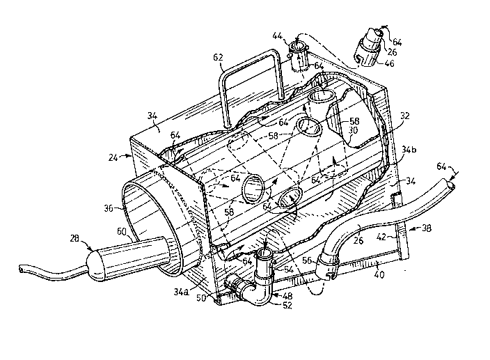
Fig. 2 is a p~ e~iv~ view of the heater according to the invention in
which portions of an outer jacket comprising the heater have been broken away toreveal the internal structure of the heater.
Referring firstly to Fig. 1, there is illustrated by way of example, a
motorised vehicle 20 of the kind driven to move over surfaces by means of an endless
track and typically used on construction sites. The vehicle 20 is typical of the heavy
equipment for which the engine block heater, according to the invention, is intended.
The engine block for the vehicle 20 is indicated by numeral 22 and is shown coupled
to the heater 24 in accordance with the invention by a pair of coolant hoses 26. An
external heat source in the form of a portable industrial-size propane torch 28 is used
with the heater in accordance with the invention and is indicated by numeral 28 in Fig.
1.
Turning now to Fig. 2, the engine block heater 24 comprises an inner
cylindrical chamber 30 having a !~-n~it~l~lin~l axis and having two ends which are open.
The outer surface of the chamber 30 defines an inner wall for a jacket 32 which is
disposed about the inner chamber so as to surround the inner chamber while leaving
the ends open. Outer walls for the jacket 32 are defined by six rectangular panels 34
disposed around the inner chamber so as to form a box.

21~073~
The end panels 34a and 34b are apertured to receive the cylinder defining
the inner chamber 30 and which protrudes through end panel 34a to define a collar 36.
It will be understood that both the inner chamber 30 and the outer jacket
32 may have different shapes, the ones shown here having been selected for convenience
in the construction of a prototype made from steel plate 1/8" (3 mm.) thick.
A pair of angle supports 38 (of which only one is shown in Fig. 2) each
comprising a horizontal leg 40 joined to a vertical leg 42 have their free ends welded to
the panels 34 comprising the outer jacket 32 so as to elevate the end of the jacket
remote from the collar 36. On the upper panel 34 at said elevated end of the jacket 32,
an opening is formed to receive a tubular connection having oppositely-disposed lugs
and defining coolant outlet means 44. The coolant outlet 44 is adapted to cooperate
with a notched coupling 46 disposed at one end of one of the hoses 26 rc~nn~tin~ the
heater 24 to the engine block 22 (Fig. 1).
A coolant inlet 48 is disposed in an aperture formed in the lower end of
the outer jacket 32 on the opposite side of the inner chamber 30. The coolant inlet
comprises a short length of threaded pipe 50, a threaded elbow 52 and a tubular fitting
54 having oppositely-disposed lugs similar to the coolant outlet 44, and adapted to
cooperate with a notched coupling 56 disposed at one end of the other hose 26 which
is attached to the engine block 22 (Pig. 1).
Five tubular conduits 58 traverse the inner chamber 30 and are in fluid
Commllni~:lfion with the outer jacket 34. The conduits 58 comprise short lengths of
pipe equally spaced along the length of the inner chamber 30 and radially staggered so
as to maximise the surface area exposed to a heat source applied to the inner chamber.
The propane torch 28 is used to supply the required heat and is disposed
with its nozzle 60 supported inside the inner chamber 30 on the collar 36.

2~4~732
.
Conveniently, a length of steel rod is shaped into a handle 62 and welded
to the upper panel 34 defining the outer jacket for the heater 24.
In use, the heater 24 is brought to the site where it is required and coupled
to the engine block, using a pair of hoses 26. The outer jacket 32 and any conduits 58
are filled with coolant, and preferably the hoses 26 are also filled with coolant so as to
minimize the occurrence of any airlocks in the coolant flow circuit between the heater
24 and the engine block 22. It will be understood that the coupling block 22 used at
the engine block will free the engine coolant so that it can readily flow through the
hoses 26.
A portable propane torch is brought to the site and ignited. With the
torch nozzle 60 disposed inside the collar 36, the flame length is adjusted to penetrate
the length of the inner chamber 30 and to surround the conduits 58. Coolant from the
engine block flows through the hoses 26 and enters the heater 24 through the inlet 48
where it is heated and rises through the conduits and around the inner chamber to exit
from the outlet 44 driven by natural convection forces. In this way, heated coolant is
brought to the engine block where it replaces colder coolant which continues to flow
as indicated by the arrows 64 through the heater 24.
It will be understood that the elegance of this invention resides in its
simplicity. The heater, according to the invention, requires no moving parts, no pump
or battery being required to circulate the coolant through the apparatus which, in
essence, is a heat exchanger. Furthermore, it will be appreciated that coolant from the
engine block is constantly circulating through the heater according to the invention and
therefore the heater is self-cooling. Finally, a forced external heat source in the form
of a propane heater is well-known to be reliable and also easily accessible in remote
locations where such heavy equipment is required.
A prototype for the invention constructed from welded steel plate had
outer flimf~ncifmc of 7" x 7" x 14" for the jacket 30 and an inner chamber with a 5ih"
diameter. The conduits 58 were fabricated from llh" diamter pipe spaced three inche

21~0732
.
apart and radiating at 36 from the centre of the inner chamber. The heater had a total
weight of approximately 30 lbs (13.6 kilos). It is estimated that the prototype heater
had a capacity for circulating 1 gallon of glycol coolant per minute. Because of its
rugged construction, the heater could bounce around on equipment or trucks all day
with no rlPtrimPnt~l effects. In one field test, a Caterpillar~ D-6 tractor, which had
been idle for two weeks was snccP~f1.lly started at an ambient temperature of -35
Celsius after the heater was operated for only 30 minutes. This is a considerable
L over available prior art devices in which several hours of operation are
required to achieve the necessary con~lition.~ for starting an engine in extreme cold
tc:l~el d~u~
The advantages of the invention are therefore easily m:lnifP~tPd in its ease
of operation and ease of care and ~ PII~IIfP However, its most attractive attribute
is that it will operate very quickly and achieve the required results within short delays
thereby allowing the heavy equipment operator to make use of his equipment as
required on short notice.

Dessin représentatif
Une figure unique qui représente un dessin illustrant l'invention.
États administratifs

2024-08-01 : Dans le cadre de la transition vers les Brevets de nouvelle génération (BNG), la base de données sur les brevets canadiens (BDBC) contient désormais un Historique d'événement plus détaillé, qui reproduit le Journal des événements de notre nouvelle solution interne.

Veuillez noter que les événements débutant par « Inactive : » se réfèrent à des événements qui ne sont plus utilisés dans notre nouvelle solution interne.

Pour une meilleure compréhension de l'état de la demande ou brevet qui figure sur cette page, la rubrique Mise en garde , et les descriptions de Brevet , Historique d'événement , Taxes périodiques et Historique des paiements devraient être consultées.

Historique d'événement

Description Date
Inactive : CIB désactivée 2011-07-27
Inactive : CIB de MCD 2010-02-01
Inactive : CIB dérivée en 1re pos. est < 2010-02-01
Inactive : CIB expirée 2010-01-01
Inactive : CIB de MCD 2006-03-11
Demande non rétablie avant l'échéance 2003-01-20
Le délai pour l'annulation est expiré 2003-01-20
Inactive : Renseign. sur l'état - Complets dès date d'ent. journ. 2002-03-06
Inactive : Abandon.-RE+surtaxe impayées-Corr envoyée 2002-01-21
Réputée abandonnée - omission de répondre à un avis sur les taxes pour le maintien en état 2002-01-21
Demande publiée (accessible au public) 1996-07-21

Historique d'abandonnement

Date d'abandonnement Raison Date de rétablissement
2002-01-21

Taxes périodiques

Le dernier paiement a été reçu le 2001-01-19

Avis : Si le paiement en totalité n'a pas été reçu au plus tard à la date indiquée, une taxe supplémentaire peut être imposée, soit une des taxes suivantes :

  • taxe de rétablissement ;
  • taxe pour paiement en souffrance ; ou
  • taxe additionnelle pour le renversement d'une péremption réputée.

Les taxes sur les brevets sont ajustées au 1er janvier de chaque année. Les montants ci-dessus sont les montants actuels s'ils sont reçus au plus tard le 31 décembre de l'année en cours.
Veuillez vous référer à la page web des taxes sur les brevets de l'OPIC pour voir tous les montants actuels des taxes.

Historique des taxes

Type de taxes Anniversaire Échéance Date payée
TM (demande, 3e anniv.) - petite 03 1998-01-20 1998-01-09
TM (demande, 4e anniv.) - petite 04 1999-01-20 1999-01-04
TM (demande, 5e anniv.) - petite 05 2000-01-20 2000-01-19
TM (demande, 6e anniv.) - petite 06 2001-01-22 2001-01-19
Titulaires au dossier

Les titulaires actuels et antérieures au dossier sont affichés en ordre alphabétique.

Titulaires actuels au dossier
BRIAN MACKENZIE
Titulaires antérieures au dossier
S.O.
Les propriétaires antérieurs qui ne figurent pas dans la liste des « Propriétaires au dossier » apparaîtront dans d'autres documents au dossier.
Documents

Pour visionner les fichiers sélectionnés, entrer le code reCAPTCHA :


Pour visualiser une image, cliquer sur un lien dans la colonne description du document. Pour télécharger l'image (les images), cliquer l'une ou plusieurs cases à cocher dans la première colonne et ensuite cliquer sur le bouton "Télécharger sélection en format PDF (archive Zip)" ou le bouton "Télécharger sélection (en un fichier PDF fusionné)".

Liste des documents de brevet publiés et non publiés sur la BDBC .

Si vous avez des difficultés à accéder au contenu, veuillez communiquer avec le Centre de services à la clientèle au 1-866-997-1936, ou envoyer un courriel au Centre de service à la clientèle de l'OPIC.


Description du
Document 
Date
(aaaa-mm-jj) 
Nombre de pages   Taille de l'image (Ko) 
Dessin représentatif 2000-06-18 1 41
Description 1996-07-20 5 220
Revendications 1996-07-20 2 61
Abrégé 1996-07-20 1 14
Dessins 1996-07-20 1 47
Rappel - requête d'examen 2001-09-23 1 129
Courtoisie - Lettre d'abandon (taxe de maintien en état) 2002-02-17 1 182
Courtoisie - Lettre d'abandon (requête d'examen) 2002-03-03 1 172
Taxes 2001-01-18 1 31
Taxes 1998-01-08 1 47
Taxes 1999-01-03 1 49
Taxes 2000-01-18 1 39
Taxes 1996-12-12 1 43
Courtoisie - Lettre du bureau 1995-03-08 2 39
Correspondance de la poursuite 1995-03-21 1 19