Sélection de la langue

Search

Sommaire du brevet 2141356 

Énoncé de désistement de responsabilité concernant l'information provenant de tiers

Une partie des informations de ce site Web a été fournie par des sources externes. Le gouvernement du Canada n'assume aucune responsabilité concernant la précision, l'actualité ou la fiabilité des informations fournies par les sources externes. Les utilisateurs qui désirent employer cette information devraient consulter directement la source des informations. Le contenu fourni par les sources externes n'est pas assujetti aux exigences sur les langues officielles, la protection des renseignements personnels et l'accessibilité.

Disponibilité de l'Abrégé et des Revendications

L'apparition de différences dans le texte et l'image des Revendications et de l'Abrégé dépend du moment auquel le document est publié. Les textes des Revendications et de l'Abrégé sont affichés :

  • lorsque la demande peut être examinée par le public;
  • lorsque le brevet est émis (délivrance).
(12) Brevet: (11) CA 2141356
(54) Titre français: HOTTE DE LABORATOIRE AVEC DEFLECTEUR D'AIR
(54) Titre anglais: FUME HOOD WITH AIR FOIL MEMBER
Statut: Durée expirée - au-delà du délai suivant l'octroi
Données bibliographiques
(51) Classification internationale des brevets (CIB):
  • B08B 15/02 (2006.01)
  • B25H 1/20 (2006.01)
(72) Inventeurs :
  • BASTIAN, JOHN M. (Etats-Unis d'Amérique)
(73) Titulaires :
  • FISHER HAMILTON SCIENTIFIC INC.
(71) Demandeurs :
  • FISHER HAMILTON SCIENTIFIC INC. (Etats-Unis d'Amérique)
(74) Agent: BORDEN LADNER GERVAIS LLP
(74) Co-agent:
(45) Délivré: 2006-03-07
(22) Date de dépôt: 1995-01-30
(41) Mise à la disponibilité du public: 1996-07-21
Requête d'examen: 2001-01-29
Licence disponible: S.O.
Cédé au domaine public: S.O.
(25) Langue des documents déposés: Anglais

Traité de coopération en matière de brevets (PCT): Non

(30) Données de priorité de la demande:
Numéro de la demande Pays / territoire Date
371,948 (Etats-Unis d'Amérique) 1995-01-20

Abrégés

Abrégé français

Une hotte de laboratoire comprend une base, des parois latérales et un couvercle qui définissent un espace de travail fermé, une surface de travail, et au moins une ouverture et une ouverture d'accès. La hotte de laboratoire comprend également un volet à guillotine pour fermer l'ouverture et un déflecteur d'air à proximité de la portion de rebord de l'ouverture pour diriger le courant d'air vers l'ouverture et dans l'espace de travail. Ce déflecteur d'air comporte une portion plate ayant une surface qui repose normalement à égalité avec la surface de travail de la hotte de laboratoire.


Abrégé anglais

A fume hood includes a base, sidewalls and a cover that define an enclosed work space, a work surface, at least one trough, and an access opening. The fume hood also includes a moveable sash for closing the opening and an air foil disposed proximate an edge portion of the opening to direct air flow through the opening and into the work space. This air foil includes a flat portion with a surface that normally lies flush with the work surface of the fume hood.

Revendications

Note : Les revendications sont présentées dans la langue officielle dans laquelle elles ont été soumises.


CLAIMS:
1. A fume hood apparatus comprising: a base member
that defines a substantially flat work surface; sidewalls; and a
cover; said base member, sidewalls and cover defining an enclosed
work space and an access opening; said apparatus including a
moveable sash for closing the opening and an air foil member
disposed proximate a bottom edge portion of the opening to direct air
flow through the opening and into the work space; said air foil
member disposed in a first position and including a flat portion,
the flat portion having a surface that lies substantially flush
with the work surface.
2. The fume hood apparatus of claim 1, wherein the
air foil member is moveable between the first position and a
second position in which the flat portion extends away from the
work space.
3. The fume hood apparatus of claim 2, wherein the
air foil member is rotatable.
4. The fume hood apparatus of any one of claims 1 to 3,
wherein the base member includes a substantially horizontal top
segment which defines the work surface and trough means for
collecting liquid flowing off the work surface.
5. The fume hood apparatus of claim 4, wherein the
trough means includes an elongate trough disposed along the
opening of the apparatus.
6. The fume hood apparatus of claim 5, wherein the
trough means includes another trough disposed inwardly of the
opening of the apparatus.
7. The fume hood apparatus of claim 2, wherein the
base member includes stop means for engaging and supporting the
airfoil member in the first position.
8. The fume hood apparatus of claim 7, wherein the
moveable sash engages the air foil member when the air foil
member lies in the first position to close the opening of the
apparatus.
9. A fume hood apparatus comprising: a base member
that defines a substantially flat work surface; sidewalls; and a
6

cover; said base member, sidewalls and cover defining an enclosed
work space and an access opening; said apparatus including a
moveable sash for closing the opening and a rotatable air foil
member disposed proximate a bottom edge portion of the opening to
direct air flow through the opening and into the work space; said
air foil member including a flat portion and being elongate and
rotatable between a first position in which the flat portion
extends generally inwardly of the work space and a surface of the
flat portion lies substantially flush with the work surface and a
second position in which the flat portion extends away from the
work space: said base member including a substantially horizontal
top segment which defines the work surface and trough means for
collecting liquid flowing off the work surface.
10. The fume hood apparatus of claim 9, wherein the
trough means includes an elongate trough disposed along the
opening of the apparatus.
11. The fume hood apparatus of claim 10, wherein the
trough means includes another trough disposed inwardly of the
opening of the apparatus.
12. The fume hood apparatus of any one of claims 9 to
11, wherein the base member includes stop means for engaging and
supporting the air foil member in the first position.
13. The fume hood apparatus of claim 12, wherein the
moveable sash engages the air foil member when the air foil
member lies in the first position to close the opening of the
apparatus.
7

Description

Note : Les descriptions sont présentées dans la langue officielle dans laquelle elles ont été soumises.

w
The present invention relates to a fume hood apparatus,
and more particularly to a fume hood apparatus with an air foil
member which facilitates the cleaning of the area proximate the
fume hood work surface using air flowing into the fume hood.
Descrsbt~on Of mhe nr;r,r nrt
Fume hoods are protective enclosures which provide
ventilated and illuminated work spaces for laboratory or other
applications. They typically include a housing and a fan for
drawing air and toxic fumes from the housing for safe discharge.
The housing includes an opening which allows access to the work
space. Air enters the fume hood through this opening to replace
the air discharged by the fan. A problem with prior fume hoods
is that they do not include means for effectively removing fumes
and other material which have settled on or proximate the work
surface of the fume hood.
Unlike prior fume hoods, the fume hood of the present
invention is a simple construction that includes an air foil
member for directing air along the fume hood's work surface to
effectively evacuate the surface and the work space of fumes and
other waste materials. This fume hood minimizes the expense of
manufacture and assembly. It includes a small number of
components which provide an effective well-ventilated work space.
,~?U~ARV OF mgF ry Nmrn~T
In accordance with this invention, a fume hood
apparatus includes a housing with sidewalk, a cover, and a base
member that defines a substantially flat work surface. The base
member, sidewalls, and cover define an enclosed work space and an
1

' CA 02141356 2004-05-19
access opening to that work space. A moveable sash closes the
opening, and an air foil member disposed a bottom .ec~,ge ,o.f the
opening directs air flow through the opening and along the work
surface of the work space.
The air foil member extends the length of the opening
and includes a flat portion. It is moveable between a first
position in which the flat portion extends generally inward of
the work space and includes a surface that lies flush with the
work surface and a second position in which the flat portion
extends away from the work space.
The base member includes a substantially horizontal top
segment which defines the work surface and trough means for
collecting liquid flowing off the work surface. The trough means
includes an elongate trough disposed along the opening of the
apparatus below the flat portion of the air foil member when the
air foil lies in the first position.
BRIEF DESCRIPTION OF. THE DRAWINGS
For a more complete understanding of this invention,
one should now refer to the embodiment illustrated in greater
detail in the accompanying drawings and described below by way of
an example of the invention. In the drawings:
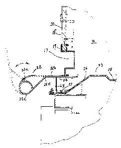
FIG. 1 is a perspective view of the fume hood apparatus
of the present invention:
FIG. 2 is an enlarged detail view of detail A in FIG.
1: and
FIG. 3 is a sectional view taken along line 3-3 in FIG.
2.
While the following disclosure describes the invention
in connection With one embodiment, one should understand that the
invention is not limited to this embodiment. Furthermore, one
should understand that the drawings are not to scale and that
graphic symbols, diagrammatic representatives, and fragmentary
views, in part, illustrate the embodiment. In certain instances,
the disclosure may not include details which are not necessary
2

for an understanding of the present invention such as
conventional details of fabrication and assembly.
DETATLD DESCRTpmTON OF THE DR_AwTNra
Turning now to the drawings, FIGS. 1-3 show the fume
hood apparatus of the present invention at 10. This fume hood
apparatus generally includes a housing with a base member 11 and
an enclosure 12 comprising a cover or top 13 and sidewalls having
a first end panel 14, a second end panel (not shown) opposite the
first end panel, a front panel 15 and a back panel (not shown)
opposite the front panel. These components, as well as those
described below, are made of metal or any other material of high
strength and rigidity.
The enclosure 12 defines a work space 16 and an access
opening 17 through which an operator may reach into the work
space. A moveable sash 18 lies slidably mounted to the enclosure
12 for closing the opening 17 and thus precluding access to the
work space 16. It includes a frame 19 and a glass panel 20. The
operator may raise the sash to allow access through the opening
17 (shown in phantom lines in FIG. 3) or lower it to close the
opening (shown in solid lines in FIG. 3).
A baffle system 21 disposed in the housing 12
cooperates with a fan (not shown) to evacuate the fumes generated
in the work space 16. The baffle system lies at the back of the
work space 16 and directs the fumes to a discharge conduit (not
shown). As the fan draws the air and fumes out of the work space
16, ambient air flows into the space, primarily through the
opening 17. An air foil member 22 directs the incoming air as
described below to facilitate evacuation of the work space 16.
The air foil member 22 lies at the bottom of the
opening 17 rotatably mounted to the housing 12. It extends the
length of the opening 17, and an operator may move it from a
first position shown in solid lines in FIG. 3 to a position shown
in phantom in that figure. In the first position the air foil
member 22 directs air into the work space 16. In the other
3

2~~13~~
1
position shown, it allows better access to the work space 16 and
surrounding area for clean up and other operations.
Air flows over and under the air foil member 22. The
member 22 has an aerodynamic shape which facilitates the movement
of air. when the member 22 lies in the first position and the
sash 18 lies open (as shown in phantom lines in FIG. 3), air
flows over and under the member 22 and into the work space 16.
When the member 22 lies in the first position and the sash 18
lies closed (as shown in solid lines in FIG. 3), air flows under
the member 22 and into the work space 16.
The air foil member 22 includes a rounded portion 22a
and a flat portion 22b. The rounded portion lies between the
flat portion 22b and a tube portion 22c that rotatably mounts the
member 22 to the enclosure 12. (The tube portion 22c may receive
enclosure protuberances that function as an axle at the ends of
the member 22; or the tube portion 22c may be slightly longer
than the other portions of the member 22 so that its end portions
may extend into pockets in the enclosure 12.) When the member 22
lies in the first position (shown in solid lines in FIG. 3), the
top surface of the flat portion 22b is flush or co-planar with
the fume hood's work surface 23. As stated above, this
arrangement allows incoming air to move fumes and other waste off
of the work surface 23 and to the back of the work space 16 where
the fan can discharge them from the fume hood.
A shelf 24 supports the air foil member 22 in the first
position and acts as a stop to prevent further clock-wise
rotation of the member 22. This shelf 24 fits snugly between a
rib 22d and a wall portion 22e of the member 22; and it rests on
pins 25 (only one pin 25 shown in FIG. 3) which lie on a top
segment 26 of the base member 1l at predetermined intervals along
the length of the shelf 24. (The shelf 24 is co-extensive with
the air foil member 22.)
The top segment 26 of the base member 11 is a plate-
like structure which defines the work surface 23. It also
defines a trough 27 generally disposed below the shelf 24 and
4

CA 02141356 2004-05-19
another trough 28 disposed inwardly of the trough 27. These
troughs 27 and 28 collect liquid run-off from the work surface
23; and they discharge their contents into discharge conduits
(not shown).
The construction of the present invention allows easy
operation of the fume hood by operators, including people with
disabilities. The sash 18 opens and closes as shown in FIG. 3:
and the air foil member 22 rotates in and out of the first
position, allowing easy cleaning of the trough 27 and easy
insertion of power cords into the work space. When the sash lies
closed and in contact with the air foil member 22 (as shown in
FIGS. 2 and 3) an opening 29 cut into the member 22 allows a
power cord P or similar device to extend out of the work space 16
and to connect with a power outlet 3Ø
While the above description and the drawings disclose
and: illustrate one embodiment, one should understand, of course,
that the invention is not limited to this embodiment. Those
skilled in the art to which the invention pertains may make
modifications and other embodiments employing the principles of
this invention, particularly upon considering the foregoing
teachings. For example, although the embodiment described above
includes flat sidewalls and a rectangular work space, the fume
hood may have a rounded work space and rounded sidewalls. In
addition, the shelf supporting the air foil member need not be
continuous and co-extensive with the air foil.
Therefore, by the appended claims, the applicant
intends to cover any modifications and other embodiments as
incorporate those features which constitute the essential
features of this invention.

Dessin représentatif
Une figure unique qui représente un dessin illustrant l'invention.
États administratifs

2024-08-01 : Dans le cadre de la transition vers les Brevets de nouvelle génération (BNG), la base de données sur les brevets canadiens (BDBC) contient désormais un Historique d'événement plus détaillé, qui reproduit le Journal des événements de notre nouvelle solution interne.

Veuillez noter que les événements débutant par « Inactive : » se réfèrent à des événements qui ne sont plus utilisés dans notre nouvelle solution interne.

Pour une meilleure compréhension de l'état de la demande ou brevet qui figure sur cette page, la rubrique Mise en garde , et les descriptions de Brevet , Historique d'événement , Taxes périodiques et Historique des paiements devraient être consultées.

Historique d'événement

Description Date
Inactive : Périmé (brevet - nouvelle loi) 2015-01-30
Inactive : TME en retard traitée 2014-01-27
Inactive : Lettre officielle 2014-01-16
Inactive : Paiement - Taxe insuffisante 2014-01-15
Lettre envoyée 2013-01-30
Inactive : CIB de MCD 2006-03-11
Accordé par délivrance 2006-03-07
Inactive : Page couverture publiée 2006-03-06
Préoctroi 2005-11-14
Inactive : Taxe finale reçue 2005-11-14
Un avis d'acceptation est envoyé 2005-05-30
Lettre envoyée 2005-05-30
Inactive : Approuvée aux fins d'acceptation (AFA) 2005-05-03
Lettre envoyée 2005-03-01
Modification reçue - modification volontaire 2004-05-19
Inactive : Dem. de l'examinateur par.30(2) Règles 2003-11-21
Modification reçue - modification volontaire 2002-04-05
Inactive : Renseign. sur l'état - Complets dès date d'ent. journ. 2002-02-25
Lettre envoyée 2002-02-25
Inactive : Dem. traitée sur TS dès date d'ent. journal 2002-02-25
Toutes les exigences pour l'examen - jugée conforme 2001-01-29
Exigences pour une requête d'examen - jugée conforme 2001-01-29
Demande publiée (accessible au public) 1996-07-21

Historique d'abandonnement

Il n'y a pas d'historique d'abandonnement

Taxes périodiques

Le dernier paiement a été reçu le 2005-12-15

Avis : Si le paiement en totalité n'a pas été reçu au plus tard à la date indiquée, une taxe supplémentaire peut être imposée, soit une des taxes suivantes :

  • taxe de rétablissement ;
  • taxe pour paiement en souffrance ; ou
  • taxe additionnelle pour le renversement d'une péremption réputée.

Veuillez vous référer à la page web des taxes sur les brevets de l'OPIC pour voir tous les montants actuels des taxes.

Historique des taxes

Type de taxes Anniversaire Échéance Date payée
TM (demande, 3e anniv.) - générale 03 1998-01-30 1998-01-02
TM (demande, 4e anniv.) - générale 04 1999-02-01 1999-01-29
TM (demande, 5e anniv.) - générale 05 2000-01-31 1999-12-20
TM (demande, 6e anniv.) - générale 06 2001-01-30 2001-01-02
Requête d'examen - générale 2001-01-29
TM (demande, 7e anniv.) - générale 07 2002-01-30 2002-01-16
TM (demande, 8e anniv.) - générale 08 2003-01-30 2002-12-23
TM (demande, 9e anniv.) - générale 09 2004-01-30 2003-12-29
TM (demande, 10e anniv.) - générale 10 2005-01-31 2005-01-21
Taxe finale - générale 2005-11-14
TM (demande, 11e anniv.) - générale 11 2006-01-30 2005-12-15
TM (brevet, 12e anniv.) - générale 2007-01-30 2006-12-08
TM (brevet, 13e anniv.) - générale 2008-01-30 2007-12-19
TM (brevet, 14e anniv.) - générale 2009-01-30 2008-12-15
TM (brevet, 15e anniv.) - générale 2010-02-01 2009-12-11
TM (brevet, 16e anniv.) - générale 2011-01-31 2010-12-17
TM (brevet, 17e anniv.) - générale 2012-01-30 2012-01-19
Annulation de la péremption réputée 2013-01-30 2013-12-19
TM (brevet, 18e anniv.) - générale 2013-01-30 2013-12-19
TM (brevet, 19e anniv.) - générale 2014-01-30 2014-01-27
2014-03-17 2014-01-27
Titulaires au dossier

Les titulaires actuels et antérieures au dossier sont affichés en ordre alphabétique.

Titulaires actuels au dossier
FISHER HAMILTON SCIENTIFIC INC.
Titulaires antérieures au dossier
JOHN M. BASTIAN
Les propriétaires antérieurs qui ne figurent pas dans la liste des « Propriétaires au dossier » apparaîtront dans d'autres documents au dossier.
Documents

Pour visionner les fichiers sélectionnés, entrer le code reCAPTCHA :


Pour visualiser une image, cliquer sur un lien dans la colonne description du document. Pour télécharger l'image (les images), cliquer l'une ou plusieurs cases à cocher dans la première colonne et ensuite cliquer sur le bouton "Télécharger sélection en format PDF (archive Zip)" ou le bouton "Télécharger sélection (en un fichier PDF fusionné)".

Liste des documents de brevet publiés et non publiés sur la BDBC .

Si vous avez des difficultés à accéder au contenu, veuillez communiquer avec le Centre de services à la clientèle au 1-866-997-1936, ou envoyer un courriel au Centre de service à la clientèle de l'OPIC.


Description du
Document 
Date
(aaaa-mm-jj) 
Nombre de pages   Taille de l'image (Ko) 
Dessin représentatif 1998-02-20 1 28
Description 1995-01-30 5 232
Page couverture 1995-01-30 1 14
Abrégé 1995-01-30 1 15
Revendications 1995-01-30 2 88
Dessins 1995-01-30 2 56
Description 2004-05-19 5 238
Revendications 2004-05-19 2 88
Dessin représentatif 2005-05-03 1 8
Page couverture 2006-02-01 1 33
Abrégé 2006-03-06 1 15
Dessins 2006-03-06 2 56
Description 2006-03-06 5 238
Rappel - requête d'examen 2001-10-02 1 129
Accusé de réception de la requête d'examen 2002-02-25 1 180
Avis du commissaire - Demande jugée acceptable 2005-05-30 1 162
Avis concernant la taxe de maintien 2013-03-13 1 171
Avis de paiement insuffisant pour taxe (anglais) 2014-01-15 1 91
Quittance d'un paiement en retard 2014-01-27 1 164
Correspondance 2005-03-01 1 15
Correspondance 2005-11-14 1 25
Correspondance 2014-01-16 1 28
Correspondance 2014-01-15 1 24
Taxes 1997-01-02 1 53