Sélection de la langue

Search

Sommaire du brevet 2141503 

Énoncé de désistement de responsabilité concernant l'information provenant de tiers

Une partie des informations de ce site Web a été fournie par des sources externes. Le gouvernement du Canada n'assume aucune responsabilité concernant la précision, l'actualité ou la fiabilité des informations fournies par les sources externes. Les utilisateurs qui désirent employer cette information devraient consulter directement la source des informations. Le contenu fourni par les sources externes n'est pas assujetti aux exigences sur les langues officielles, la protection des renseignements personnels et l'accessibilité.

Disponibilité de l'Abrégé et des Revendications

L'apparition de différences dans le texte et l'image des Revendications et de l'Abrégé dépend du moment auquel le document est publié. Les textes des Revendications et de l'Abrégé sont affichés :

  • lorsque la demande peut être examinée par le public;
  • lorsque le brevet est émis (délivrance).
(12) Demande de brevet: (11) CA 2141503
(54) Titre français: REGULATEUR D'INTENSITE AUTOMATIQUE POUR PHARES D'AUTOMOBILE
(54) Titre anglais: AUTOMATIC DIMMER CONTROLLER FOR AUTOMOBILE HEADLAMPS
Statut: Réputée abandonnée et au-delà du délai pour le rétablissement - en attente de la réponse à l’avis de communication rejetée
Données bibliographiques
(51) Classification internationale des brevets (CIB):
  • B60Q 01/14 (2006.01)
  • B60Q 01/076 (2006.01)
(72) Inventeurs :
  • XU, KOK CHENG (Chine)
(73) Titulaires :
  • SHENYAN ENTERPRISE INTERNATIONAL PTE LTD.
(71) Demandeurs :
  • SHENYAN ENTERPRISE INTERNATIONAL PTE LTD. (Singapour)
(74) Agent: OYEN WIGGS GREEN & MUTALA LLP
(74) Co-agent:
(45) Délivré:
(22) Date de dépôt: 1995-01-31
(41) Mise à la disponibilité du public: 1995-08-02
Licence disponible: S.O.
Cédé au domaine public: S.O.
(25) Langue des documents déposés: Anglais

Traité de coopération en matière de brevets (PCT): Non

(30) Données de priorité de la demande:
Numéro de la demande Pays / territoire Date
94-2-02046.4 (Chine) 1994-02-01

Abrégés

Abrégé anglais


An automatic dimmer that is actuated automatically during cars'
confrontation with each other comprises a housing and a convex
lens contained in the housing for receiving the light from a
headlamp, the outer surface of the convex lens being covered with
layer of transparent coating film having refractivity higher
than that of the lens. The housing is integral with the
controller circuit which is of thick film in type thereby
reducing the overall dimension of the controller. The interior
is compact in structure and is provided with cushioning, loose-
preventing structure thereby ensuring the sensitivity of the
controller. A further feature is that the universal ball joint
having been displaced to the free end of the supporting lever
allows decrement of the controller in its weight. The additional
level gauge facilitates the location in installation.

Revendications

Note : Les revendications sont présentées dans la langue officielle dans laquelle elles ont été soumises.


C L A I M S
1. An automatic dimmer controller comprising a housing, a
convex lens contained in the housing for receiving the light from
a headlamp, and a photoelectric sensor mounted at the focus of
the convex lens for receiving the light converged by the lens,
characterized in that the housing of the controller is a cup-
shaped envelope with a cylindrical interior, the structure of
which including a resilient rubber pad, a control-circuit chip, a
light-conducting sleeve, a photosensitive sensor, a convex optic
and a pressing ring; the interrelationship of these components
runs as follows: the chip lying on the rubber pad provided in the
cup bottom of the envelope is fixedly connected with the sensor
located in the central position of the bottom of the light-
conducting sleeve; the rim of the convex lens presses against the
periphery of the light-conducting sleeve is in turn pressed by
the pressing ring, which is integrated with the cylindrical cup
opening of the housing in close running fit; the conductors of
the chip are led out through the housing wall.
2. A controller as claimed in claim 1, characterized in that a
level gauge of bubble type is attached on the housing.
3. A controller as claimed in claim 1, characterized in that
the housing has an integral supporting lever with a universal
ball joint on its free end matching with a latching bushing of
the same type; integral with the bushing is a locating gripping

clamp.
4. A controller as claimed in claim 1, characterized in that
the outer surface of the convex lens is provided with a layer of
lens having refractivity higher than that of the convex lens.
5. A controller as claimed in claim 1, characterized in that
said lens is a layer of transparent coating film.

Description

Note : Les descriptions sont présentées dans la langue officielle dans laquelle elles ont été soumises.

` ~ . 21~03
204~; . 4
AT~OMAl'IC .~31~.. .r.~ CCh~Ol;L13:R F~ 2LI.~ r ~:~S
The present utility model rela~es to an automobile headlamp
I dimmer oontroller that is aetuated automa~ically when another c~r
j is approaching head-on.
A car travelling a~ night along a non-illumina~ed road w~th the
headligh~ in Ith~gh~lamp" position illu~inatlng distant road
surface is apt to cause accident if it keeps on direating th~
glare to a head-on appro~ching car, thereby affecti~g the normal
; oper~on of ~he drlver in that car. I~ is therefore provided ~n
the ~raf~i_ regulation ~hat the head-lights have to be dipped
into "low-lamp" poSit~o~ when two ca~s are 100-200 meters apart
an~ approaching each other. Such a dipplng, used to be done by
the driver, is carried out by means of an ~utomatiC ~mm~r
! controller ~hich comes ~nto ~Xistence in re~ent years.
~he existing automatic d;mm~r controller which is, for examp~e, a
technical solution in a patent for utili~y model No. 91232502.X
provides a pho~oelectric probe separated from a controller to
co~rol a ~ r b~ receiving light sighal from a c~r app~oaching
at a near distance. A nu~b~r of dee~s have ~een found in th~
applic~t~on o~ such a probe, ~uch as the loosene~s prone to occur
betwee~ the componen~s o~ the probe af~er usage for a period
resulting in ~isp~a~ent of photosensitive sensor and in the
misplacemen~ o~ convergent lens focus whlch lead to the failu~e
o~ the con~roller, the overweight o~ the probe assembly, ~he
. ~J

i 2~4~503
~elative difficulty in use ~nd in ke~pins ~he alig~ent of same,
a~d to the mis~udgement incu~red ~y interference ~rom stray light
etc.
The objec~ o~ ~he present utility model is to pro~ide a novel
~echnical arran~ement ~or a ~ er controller to ove~come ~he
defects residing ln the abGvelllentioned utility model.
The presen~ util~ty model includes the following:
An autom~tic ~m~r controller ~omprisi~g a housing, a convex
lens contained in the housing for receiving ~he li~h~ fro~ a
headlamp, and a photoelectric sensor mount~d at the focus of the
convex lens for receiving the light converged hy the lens.
The housing of the controller is a cylindrical cup, the structure
of which includes a resilient r~bbe~ buffer, a cont~ol-circuit
chip, a l~ght-transmitting sleeve, a photoelectric sensor, a lens
and a convex op~ic assembly, and a pressing rins. The
interrelat~onship of these com~onents r~ns as follows: ~he chip
rest~ng on the ru~er bu~er provided in the ~ottom o~ ~he
housing cup is fixedly connected to the sensor loca~ed in the
central position of the bot~om o~ the light-transmit~ing sleeve.
~he ri~ of the convex lens presses against the periphery of ~he
l~gh~-t~ansmitting slceve and is in turn presse~ by the pressure
ring, which is in~e~ral w~th the cyli~drical cup opening of the
houslng in close running fit. ~he conductors of the chip are led
out ~h~ough the housing ~all. The pro~e may be provided w~th a
level gauge of bu~ble type on the outside o~ t~e wall. Th~
!

` . 214150~
J
housing has an integrated supporting lever ~ith a universal bal~
joint on its free end matching with a latc~ing bushing of the
same type. Integral wi~h the bushing is a p~sitioning clamp. ~n
the outer surface of the ~onvex lens there is a layer of lens the
refr~ctivity of which is higher than that of the convex lens.
Said layer of lens may be a tran5p~rent coating film.
The present utility model ~ea~ures in that the probe is integral
~ith the çon~roller circuit, the overall ~imen.C~on of the
contro~er is reduced ~y ad~ption of a thick-film clrcuit and the
interio~ thereof being cOmpaCt in -~tructure and, in addition,
provided with a cushioning, loose-preventing structure is thereby
ensuring the sensitivity of the controller, A ~urther feat~re is
thzt the universal ball joint having been displaced to the free
end o~ the s~pporting lever allows dec~emen~ of ~he controller in
its weight. The additional level gauge facilitate~ the ~ocation
in insta~lation, which is thus ensuring a sta~le operating
con~ition. Still another ~eature lies in that on the outer
sur~ace of the convex lens, namely the incid~nt surace of the
signal, there has been provided with a lens having refractiYity
higher than ~hat of the convex lens. According to the re~raction
principle o~ natural l~gh~ revealed in ~he conventional optics,
the ~t~ay light from both ~ides o the road su~ace w?ll be
reflected when the incidence the~eo~ is la~ger than the critical
angle of total ref1ecti on, while another portion of: stray light
of though smaller incidence than the critical angle of total
reflection ~u~ larger t~an the convergent incidence o~ the con~ex
i
;.J

2~t ~
lens a~er h~ving ~en refracted to ~he o~ter surfaCe o~ the lens
will never reach the contacts of the photosPnsiti~e sensor at the
~ocus, which th~s, in contrzst, el;min~tes su~stan~ial portion o~
interference ~ause~ by t~e st~a~ light, thereby improving the
accur~cy in collection of the light signal from the lamp.
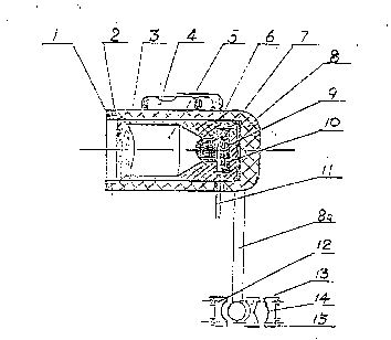
An e~odiment of the present u~ility model is ~llustrated in the
accompanying drawings, in which
Figure 1 is the schemat~c diagram o~ the c~c~ r_ct~a-s ~ _h2
pr~9n~ design;
Figure 2 is the schematic diagram of the mounting position of the
presen~ design in t~e driving compartmen~ of a cart
~n the drawings, the re~erence numbers represent:
1. pressing ~ing 2. organic ~ilm
3. convex lens 4. lev~l gauge
5. light-conducting sleeve 6. photosensitive sensor
7. control-circuit chip 8. housing
8a. housing supporting le~er ~. cushioning r~bber pad
10. cushioning ring 11 signal leads
12. universal ball ~o~n~ 13. bushing of the ball 30i~
14. locating clamp lS. la~ching bolt
The p~esent ~esign will be specifically described i~ aombi~ation
with the drawings.
~he controller according to the present design has a housing 8,
the in~er~or part of which is in a sh~pe of cyli~drical cup wi~h

21~150~
a cushioning cup 10 situated at its bottom and a re~ilient ~ubbe~
pad g located therein. On the pad 9 the~e lies a control-circuit
chip 7 integrated with a photo~ehsitive sensor 6, which is
arranged in the centre of the base of a light-cond~cting sleeve S
at the focus of a convex lens 3. The peripheral edge o~ the
sleeve presses against the chip. The outer s~rface of the cohvex
lens is covered with a plane lens 2 having higher i~dex of
re~raction, which also may be a layer of transparent organic
coating film, for eliminating part of the interference ~rom part
~f the st~ay li~ht, The interior æurface of the convex lens
presses ~irmly against the light-con~ucting sleeve 5 A pressing
ring 1 pressing the convex lens against the o~ter periphery of
the sleeve 5 is arranged on the peripheral rim o~ the ho~sing
port, The pres~ing ring 1 ~nd the housing 8 forms a tight fit o~
engaging type to overcome the drawback of the threaded connection
which is prone to looseness under vibration. All parts between
the pad g and the ring l are resili~ntly pressed in position. ~o
gap will occur due to vib~ation thereby ensuring assembly
accuracy of the controller. A level gauge 4 provided outside the
housing 8 is ~raduated ~ith scale of levelness thus facilit~ting
the location o~ the convex lens. The housing 8 has an integ~al
supporting lever 8a wi~h a universal ball joint 12 o~ its free
end coordinating with and latched in positio~ by the bushing 13.
The bushi~g 13 integrated with a locating clamp 14 and
coordinated by the latching ~olt 15 can be co~venien~ly mounted
on the f~a~e 16 of the mirror 17 in the driving comparb~ent.
Signal lines and power line 8 are led out through the wall of the

5 0 ~
ho~sins 8
The controller of t~e present des~gn is small in si2e, compact in
structure, excellent in integrality, easy ~or installation and is
relatively sood in prevention o~ interference ~rom the st~y
light and in o~erational stability.

Dessin représentatif
Une figure unique qui représente un dessin illustrant l'invention.
États administratifs

2024-08-01 : Dans le cadre de la transition vers les Brevets de nouvelle génération (BNG), la base de données sur les brevets canadiens (BDBC) contient désormais un Historique d'événement plus détaillé, qui reproduit le Journal des événements de notre nouvelle solution interne.

Veuillez noter que les événements débutant par « Inactive : » se réfèrent à des événements qui ne sont plus utilisés dans notre nouvelle solution interne.

Pour une meilleure compréhension de l'état de la demande ou brevet qui figure sur cette page, la rubrique Mise en garde , et les descriptions de Brevet , Historique d'événement , Taxes périodiques et Historique des paiements devraient être consultées.

Historique d'événement

Description Date
Le délai pour l'annulation est expiré 1998-02-02
Demande non rétablie avant l'échéance 1998-02-02
Réputée abandonnée - omission de répondre à un avis sur les taxes pour le maintien en état 1997-01-31
Demande publiée (accessible au public) 1995-08-02

Historique d'abandonnement

Date d'abandonnement Raison Date de rétablissement
1997-01-31
Titulaires au dossier

Les titulaires actuels et antérieures au dossier sont affichés en ordre alphabétique.

Titulaires actuels au dossier
SHENYAN ENTERPRISE INTERNATIONAL PTE LTD.
Titulaires antérieures au dossier
KOK CHENG XU
Les propriétaires antérieurs qui ne figurent pas dans la liste des « Propriétaires au dossier » apparaîtront dans d'autres documents au dossier.
Documents

Pour visionner les fichiers sélectionnés, entrer le code reCAPTCHA :


Pour visualiser une image, cliquer sur un lien dans la colonne description du document. Pour télécharger l'image (les images), cliquer l'une ou plusieurs cases à cocher dans la première colonne et ensuite cliquer sur le bouton "Télécharger sélection en format PDF (archive Zip)" ou le bouton "Télécharger sélection (en un fichier PDF fusionné)".

Liste des documents de brevet publiés et non publiés sur la BDBC .

Si vous avez des difficultés à accéder au contenu, veuillez communiquer avec le Centre de services à la clientèle au 1-866-997-1936, ou envoyer un courriel au Centre de service à la clientèle de l'OPIC.


Description du
Document 
Date
(aaaa-mm-jj) 
Nombre de pages   Taille de l'image (Ko) 
Description 1995-08-01 6 211
Abrégé 1995-08-01 1 25
Revendications 1995-08-01 2 47
Dessins 1995-08-01 2 21
Dessin représentatif 1998-08-02 1 11
Courtoisie - Lettre du bureau 1995-04-02 1 39
Correspondance reliée au PCT 1996-08-26 3 97
Courtoisie - Lettre du bureau 1996-02-06 1 18