Sélection de la langue

Search

Sommaire du brevet 2141621 

Énoncé de désistement de responsabilité concernant l'information provenant de tiers

Une partie des informations de ce site Web a été fournie par des sources externes. Le gouvernement du Canada n'assume aucune responsabilité concernant la précision, l'actualité ou la fiabilité des informations fournies par les sources externes. Les utilisateurs qui désirent employer cette information devraient consulter directement la source des informations. Le contenu fourni par les sources externes n'est pas assujetti aux exigences sur les langues officielles, la protection des renseignements personnels et l'accessibilité.

Disponibilité de l'Abrégé et des Revendications

L'apparition de différences dans le texte et l'image des Revendications et de l'Abrégé dépend du moment auquel le document est publié. Les textes des Revendications et de l'Abrégé sont affichés :

  • lorsque la demande peut être examinée par le public;
  • lorsque le brevet est émis (délivrance).
(12) Brevet: (11) CA 2141621
(54) Titre français: DISPOSITIF ANTIREFOULEMENT POUR ROBINETS
(54) Titre anglais: VACUUM BREAKER FOR FAUCETS
Statut: Périmé et au-delà du délai pour l’annulation
Données bibliographiques
(51) Classification internationale des brevets (CIB):
  • F16K 11/20 (2006.01)
  • E03C 1/04 (2006.01)
  • E03C 1/10 (2006.01)
  • F16K 24/02 (2006.01)
(72) Inventeurs :
  • FREIER, DONALD P. (Etats-Unis d'Amérique)
  • MATZNICK, ANDREW H. (Etats-Unis d'Amérique)
(73) Titulaires :
  • KOHLER CO.
(71) Demandeurs :
  • KOHLER CO. (Etats-Unis d'Amérique)
(74) Agent: MARKS & CLERK
(74) Co-agent:
(45) Délivré: 1999-06-15
(22) Date de dépôt: 1995-02-01
(41) Mise à la disponibilité du public: 1995-08-03
Requête d'examen: 1996-03-18
Licence disponible: S.O.
Cédé au domaine public: S.O.
(25) Langue des documents déposés: Anglais

Traité de coopération en matière de brevets (PCT): Non

(30) Données de priorité de la demande:
Numéro de la demande Pays / territoire Date
191,244 (Etats-Unis d'Amérique) 1994-02-02

Abrégés

Abrégé anglais


A faucet with a vacuum breaker for a pull-out
spray head plumbing fixture is provided. The vacuum
breaker is in the faucet housing and provides a guide for
and surrounds an extendible and retractable hose connected
to the pull-out spray head. The vacuum breaker has a
flapper valve stretch fitted over a body member of the
vacuum breaker. The body member also affords pivotal
attachment of a spout. A tubular guide for the hose also
provides a quick connect or disconnect feature.

Revendications

Note : Les revendications sont présentées dans la langue officielle dans laquelle elles ont été soumises.


The embodiments of the invention in which an
exclusive property or privilege is claimed are defined as
follows:
1. A faucet comprising a faucet housing having a
first bore in communication with a fluid inlet, a valve
unit positioned in the first bore for regulating fluid
flow from the fluid inlet to an outlet of the valve unit,
a second bore in the housing that is not co-axial to the
first bore, a pull-out spray unit mounted to a tube, the
tube extending into the second bore and being axially
movable therein, a conduit operatively connected between
the valve unit outlet and the tube, and a vacuum breaker
positioned in the housing, the vacuum breaker including a
guide member positioned therein with a portion of the
tube passing therethrough.
2. The faucet of claim 1, wherein the portion of
the tube is located concentrically within the guide
member.
3. The faucet of claim 2, wherein the vacuum
breaker includes a base section, having a multiplicity of
openings extending therethrough, and there is a flapper
valve mountable in a closed position over the openings.
4. The faucet of claim 3, wherein the guide member
includes a threaded portion for connection with the
second bore.
5. The faucet of claim 3, wherein the base section
is coupled to the guide member by an internal retaining
ring member.
6. The faucet of claim 3, wherein the guide member

is located in the second bore.
7. The faucet of claim 1, wherein the first and
second bores have longitudinal axes which are at an angle
of less than ninety degrees with respect to one another.
8. A vacuum breaker for use with a faucet having a
pull-out spray unit comprising a cup shaped body member
having a base portion with openings extending
therethrough, a flapper valve mounted in a closed
position over the openings, a cylindrical guide connected
to the base portion for guiding a tubular member through
the body member, and connecting means operatively
associated with the body member for connecting the body
member to a valve housing.
9. The vacuum breaker of claim 8, wherein the
connecting means are screw threads disposed on the
cylindrical guide.
10. The vacuum breaker of claim 8, wherein the
flapper valve is of a one-piece construction, the flapper
valve composed of an elastic material and being stretch
fitted onto the body member.
11. The vacuum breaker of claim 8, wherein the body
member has an annular lip portion extending outwardly
from the body member to provide a bearing surface for a
faucet spout.
12. The vacuum breaker of claim 8, wherein the
cylindrical guide is positioned concentrically with
respect to the body member.

Description

Note : Les descriptions sont présentées dans la langue officielle dans laquelle elles ont été soumises.

T ,~
6 ~ 1 ~
This invention relates primarily to vacuum breakers
ior faucets- More particularly, the invention relates to
vacuum breakers for use with faucets having a pull-out
spray function.
Pull-out spray head faucets have become increasin~ly
s is particularly true ~ith
kitchen and bar sin~ faucets. These tvpes of faucets,
however, pose special problems in that if the spray head
is placed in contact with dirty water, and the supply of
water is interrupted, the water supply could become
contaminated by a back siphoning of the dirty water.
Vacuum breakers were therefore pro~ided in conjunction
with such pull-out spray heads~
Prior art vacuum breakers for pull-out spray heads
have shortcomings in that they present valving devices
which require specially designed venting passage9.
Others are multicomponent val~in~ devices and/or devices
which are not easily installed or repaired. Neither do
they afford optimal guidance for the extendible and
retractable hose. Thus, it can be seen that a need
Pr~Ved vacuum breaker f
thi5 invention is to pro id
of the above kind ~hich can effect a vacuum breaker
function in a pull-out spray apparatus as ~ell as provide
guidance oi the extendible and retractable hose without
requiring additional vent holes through the housing.
The present invention provides a ~aucet comprising a
faucet housing having a first ~ore in communication with
a fluid inlet, a valve unit positioned in the first bore
,.~
}tL~

2 ~
for regulating fluid flow from the fluid inlet to an
outlet of the valve unit, a second bore in the housing
that is not co-axial to the first bore, a pull-out spray
unit mounted to a tube, the tube extending into the
second bore being axially movable therein, a conduit
operatively connected between the valve unit outlet tube,
and a vacuum breaker positioned in the housing, the
vacuum breaker including a guide member positioned
therein with a portion of the tube passing therethrough.
Preferably the portion of the tube is located
concentrically within the guide member. The vacuum
breaker member may include a base section having a
multiplicity of openings extending therethrough, and a
flapper valve closes the openings. The guide member may
include a threaded end portion for connection with the
second bore.
The present invention also provides a vacuum breaker
for use with a faucet having a pull-out spray unit
comprising a cup shaped body member having a base portion
with openings extending therethrough, a flapper valve
mounted in a closed position over the openings, a
cylindrical guide connected to the base portion for
guiding a tubular member through the body member, and
connecting means operatively associated with the body
member for connecting the body member to a valve housing.
In accordance with the invention, the combined guide
and vacuum breaker is easily connected or disconnected
from a valve housing and is composed of few parts. The
faucet can easily and efficiently be installed and
~s.

2a
operated, can be manufactured with a few parts and thus
at reduced costs, can be easily repaired, and permits a
compact and an esthetic design. The faucet reduces
scraping of the hose on the interior sides of the
housing.
These and still other features and advantages of the
invention will be apparent from the description which
follows. In the detailed description below, a preferred
embodiment of the invention will be described in
reference to the accompanying drawings. The embodiment
does not represent the full scope of the invention.
Rather the invention may be employed in other
embodiments.
In the drawings:
Figure 1 is a front elevational view showing a
faucet employing the vacuum breaker of this invention;

214162~
, ~,
~_ -3-
Figure 2 is a sectional view taken along line 2-2
of Figure l;
Figure 3 is an enlarged detailed view of the
vacuum breaker shown in a closed position;
Figure 4 is a view generally similar to Figure 3
showing the vacuum breaker in an open position;
Figure 5 is a sectional view taken along line 5-5
of Figure 3; and
Figure 6 is an exploded perspective view of the
vacuum breaker parts shown in Figures 3 and 4.
Referring to Figures 1 and 2, the vacuum breaker,
generally 10, is shown in conjunction with a faucet,
generally 12, having a valve body 14 with a first axial
bore 11 and a second axial bore 13 which is not co-axial
with the first. Valve body 14 is secured to an escutcheon
20 and the counter 15 top by the C-clamp 16 which is
pressed against the bottom of the counter by the sleeve
18. A nut 19 threaded on the post 17 forces the sleeve 18
against C-clamp 16. A spacer 22 is provided in the
escutcheon 20 in addition to the gaskets 21 and 23 for
mounting the valve body 14 on the counter 15.
Hot and cold water pipes 26 and 27 deliver hot
and cold water to the valve insert 24 which is sealed in
the valve body 14 by the 0-rings 25. Valve insert 24 has
suitable passages for delivering the hot and cold water to
the valve 30. A mounting nut 32 secures the valve 30 in
the valve body 14, and a bonnet 34 covers the nut 32 and
is connected thereto. Valve 30 is of the ceramic disk
cartridge type having a stationary disk with hot and cold
water passages extending therethrough and a movable disk
operable by the valve stem 39 for regulating the flow of
water to outlet passage 42 in the insert 24. A valve
regulating handle 36 is connected to the valve stem 39 by
the screw 37, a washer 38, and a decorative dome 40 is
placed thereover.
A check valve 44 is placed in the outlet passage

21416~
~,~
~,
~_ -4-
42 which is retained therein by the retainer 45. Outlet
passage 42 delivers mixed hot and cold water to outlet
line 28 which in turn is connected to the flexible hose
50. Hose 50 extends back through valve body 14 and into
spout 52 where it is attached to spray head 54 by the nut
49 threadably engaging housing 56. A check valve 57 is
located in a housing 56. A spray head 54 is seated on the
end of spout 52 when it is not extended and is guided
therein by insert 55. The weight 51 on hose 50 assists in
a retractable seating.
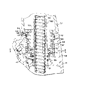
Disposed in a compartment 48 of the valve body 14
is the vacuum breaker 10, the details of which are seen in
Figures 3-6. Vacuum breaker 10 has a cylindrical body 59
for pivotally receiving an extending portion 53 of spout
52. Stabilizing rings 62 are disposed in annular grooves
68 in the extending portion 53 for contact with the inside
of body 59. A split ring 66 connects the exten~ing
portion 53 to the cylindrical body 59. An annular lip 64
is placed between the spout 52 and the upper ends of body
59 to serve as a bearing support for spout 52. An O-ring
63 provides a seal between vacuum breaker body 59 and
valve body 14.
A guide tube 60 is concentrically located in
vacuum breaker body 59 and is attached to the valve body
14 by the threads 61. Vacuum breaker body 59 is retained
on the tube 60 by the retaining ring 70 engaging an
increased diameter section 67. This holds the base
section 71 and a reduced diameter portion 69 against the
shoulder 65 extending from tube 60. O-rings 74 are placed
between the guide tube 60 and the valve body 14, as well
as base section 71 to effect a proper seal.
A diaphragm 72, composed of an elastic material,
is stretch fitted onto the reduced diameter portion 69 of
body 59 and retained thereon by the collar portion 73. An
annular portion 76 extends from the collar portion 73 for
purposes of covering apertures 75 in the base section 71

214162~
~,.,
_ -5-
of body 59.
Under normal operating conditions, the annular
portion 76 covers the apertures 75 so that pressurized
water in compartment 48 cannot flow through the apertures
75. This would be the normal operating condition of the
faucet 12 when pressurized water is flowing therethrough.
It should be noted that even when there is not a
pressurized condition in compartment 48, the annular
portion 76 covers the apertures 75. This is illustrated
in Figure 3.
In the event of a loss of pressure in the water
supply lines 26 and 27, and the spray head 54 were left in
the gray or dirty water of a sink, the gray water could be
drawn into the water supply by means of the hose 50 and
outlet line 28. A reduction in pressure in the insert 24,
passage 42 and compartment 48 causes the annular portion
76 to be drawn downwardly and away from the apertures 75
thus drawing air from the atmosphere in from the spout 52
to break the vacuum. Air is easily drawn into the spout
52 when the spray head 54 is not seated on the end
thereof, as well as through slots 79 in lip 64 of body
59. Diaphragm 72 thus functions as a one-piece flapper
valve.
An important feature of the vacuum breaker 10 is
the positioning in a compartment for the spout 52. This
obviates having to design a separate channel or passageway
for venting purposes as it is effected through the spout
52. Another important feature is the guide tube 60. This
not only serves as a guide for hose 50 as it is extended
and retracted from spout 52 but also provides a quick
assembly or disassembly of the vacuum breaker 10 in view
of the threaded connection 61. Openings are provided at
77 and 78 for tool insertion.
It will therefore be appreciated that a vacuum
breaker 10 is provided which simplifies the design of the
valve body in eliminating air passages therethrough. By

21~1621
~_ -6-
placing the vacuum breaker 10 adjacent and below the valve
30, a compact design is realized. Further, ease of
assembly is afforded by a guide tube for the pullout hose,
the guide tube being easily connected or disconnected.
Still another feature of the vacuum breaker 10 is
the simplified construction. It requires only a one-piece
diaphragm 72 stretched over the body 59 of the vacuum
breaker 10.
Thus, the invention provides an improved valve
assembly. While a preferred embodiment has been described
above, it should be readily apparent to those skilled in
the art that a number of modifications and changes may be
made without departing from the spirit and scope of the
invention. For example, while a particular plumbing valve
has been shown, other valves can be used with the vacuum
breaker. Also, the specific materials mentioned are not
the only materials which can be used.

Dessin représentatif
Une figure unique qui représente un dessin illustrant l'invention.
États administratifs

2024-08-01 : Dans le cadre de la transition vers les Brevets de nouvelle génération (BNG), la base de données sur les brevets canadiens (BDBC) contient désormais un Historique d'événement plus détaillé, qui reproduit le Journal des événements de notre nouvelle solution interne.

Veuillez noter que les événements débutant par « Inactive : » se réfèrent à des événements qui ne sont plus utilisés dans notre nouvelle solution interne.

Pour une meilleure compréhension de l'état de la demande ou brevet qui figure sur cette page, la rubrique Mise en garde , et les descriptions de Brevet , Historique d'événement , Taxes périodiques et Historique des paiements devraient être consultées.

Historique d'événement

Description Date
Le délai pour l'annulation est expiré 2010-02-01
Lettre envoyée 2009-02-02
Inactive : CIB de MCD 2006-03-11
Lettre envoyée 2003-03-20
Inactive : TME en retard traitée 2001-02-08
Accordé par délivrance 1999-06-15
Inactive : Page couverture publiée 1999-06-14
Inactive : Correspondance - Taxe finale 1999-04-16
Lettre envoyée 1999-02-25
Inactive : Taxe finale reçue 1999-02-19
Préoctroi 1999-02-19
Inactive : Taxe finale reçue 1999-01-29
Lettre envoyée 1998-08-21
Un avis d'acceptation est envoyé 1998-08-21
Inactive : Dem. traitée sur TS dès date d'ent. journal 1998-08-17
Inactive : Renseign. sur l'état - Complets dès date d'ent. journ. 1998-08-17
Inactive : Approuvée aux fins d'acceptation (AFA) 1998-06-12
Toutes les exigences pour l'examen - jugée conforme 1996-03-18
Exigences pour une requête d'examen - jugée conforme 1996-03-18
Demande publiée (accessible au public) 1995-08-03

Historique d'abandonnement

Il n'y a pas d'historique d'abandonnement

Taxes périodiques

Le dernier paiement a été reçu le 1999-01-27

Avis : Si le paiement en totalité n'a pas été reçu au plus tard à la date indiquée, une taxe supplémentaire peut être imposée, soit une des taxes suivantes :

  • taxe de rétablissement ;
  • taxe pour paiement en souffrance ; ou
  • taxe additionnelle pour le renversement d'une péremption réputée.

Veuillez vous référer à la page web des taxes sur les brevets de l'OPIC pour voir tous les montants actuels des taxes.

Historique des taxes

Type de taxes Anniversaire Échéance Date payée
TM (demande, 3e anniv.) - générale 03 1998-02-02 1998-01-21
TM (demande, 4e anniv.) - générale 04 1999-02-01 1999-01-27
Taxe finale - générale 1999-02-19
TM (brevet, 5e anniv.) - générale 2000-02-01 2000-01-24
Annulation de la péremption réputée 2001-02-01 2001-02-08
TM (brevet, 6e anniv.) - générale 2001-02-01 2001-02-08
TM (brevet, 7e anniv.) - générale 2002-02-01 2002-01-22
TM (brevet, 8e anniv.) - générale 2003-02-03 2003-02-03
TM (brevet, 9e anniv.) - générale 2004-02-02 2003-02-03
TM (brevet, 10e anniv.) - générale 2005-02-01 2004-12-29
TM (brevet, 11e anniv.) - générale 2006-02-01 2006-01-06
TM (brevet, 12e anniv.) - générale 2007-02-01 2007-01-18
TM (brevet, 13e anniv.) - générale 2008-02-01 2007-12-31
Titulaires au dossier

Les titulaires actuels et antérieures au dossier sont affichés en ordre alphabétique.

Titulaires actuels au dossier
KOHLER CO.
Titulaires antérieures au dossier
ANDREW H. MATZNICK
DONALD P. FREIER
Les propriétaires antérieurs qui ne figurent pas dans la liste des « Propriétaires au dossier » apparaîtront dans d'autres documents au dossier.
Documents

Pour visionner les fichiers sélectionnés, entrer le code reCAPTCHA :


Pour visualiser une image, cliquer sur un lien dans la colonne description du document. Pour télécharger l'image (les images), cliquer l'une ou plusieurs cases à cocher dans la première colonne et ensuite cliquer sur le bouton "Télécharger sélection en format PDF (archive Zip)" ou le bouton "Télécharger sélection (en un fichier PDF fusionné)".

Liste des documents de brevet publiés et non publiés sur la BDBC .

Si vous avez des difficultés à accéder au contenu, veuillez communiquer avec le Centre de services à la clientèle au 1-866-997-1936, ou envoyer un courriel au Centre de service à la clientèle de l'OPIC.


Description du
Document 
Date
(aaaa-mm-jj) 
Nombre de pages   Taille de l'image (Ko) 
Page couverture 1995-09-29 1 16
Abrégé 1995-08-03 1 18
Description 1995-08-03 6 289
Revendications 1995-08-03 2 78
Dessins 1995-08-03 3 120
Dessin représentatif 1999-06-08 1 14
Description 1998-05-20 7 267
Revendications 1998-05-20 2 67
Page couverture 1999-06-08 1 36
Avis du commissaire - Demande jugée acceptable 1998-08-21 1 166
Quittance d'un paiement en retard 2001-02-14 1 169
Avis concernant la taxe de maintien 2009-03-16 1 171
Correspondance 2003-03-21 1 10
Correspondance 1999-02-25 1 9
Correspondance 1999-01-29 1 41
Correspondance 1999-02-19 1 40
Correspondance 1999-04-16 3 86
Taxes 1997-01-06 1 46
Correspondance de la poursuite 1995-02-01 10 454
Courtoisie - Lettre du bureau 1996-03-27 1 61
Correspondance de la poursuite 1996-03-18 1 27
Correspondance de la poursuite 1996-07-23 2 35
Correspondance de la poursuite 1996-07-23 1 46