Note : Les descriptions sont présentées dans la langue officielle dans laquelle elles ont été soumises.
. 214 2 014
~PEA~S o 5 ~UG 1994
MULTIPLE INTERACTING DVE ALGORITHM
FIELD OF THE rNVENTIO~I
The present invention relates to active cancellation systems for repetitive or non-
repetitive phenomena, and, more specifically, to the extension of the digital virtual earth
technology to applications involving multiple interacting sensors and actuators
BACKGROUND OF TEIE ~rVENTION
In U.S. Patent Number 5,105,37,' by the same inventor, hereby incorporated by
0 reference herein, there is described an active cancellation system for repetitive or non-
repetitive phenomena which estimates the noise signal by subtracting the predicted
effects of the cancellation signal from the residual sensor signal. In this single input,
single output system, an LMS filtered-x algorithm is employed to adapt the cancellation
filter coeff~cients. The adaptive filter produces the cancellation signal by filter;ng the
estimated noise with filter weights that are adapted using the residual signal and the--
estimated noise convolved with the system impulse response. The single channel version
of the DVE algorithm is described by the equations:
NC-I
Xk = ek - ~; Cl Yk-l
1=0
NF~7 - I
Yk = ~ ~ Am,k Xk-m
m=O
NC-I
gk = ~ Cl Xk_l
1=0
Am k+l = Am,k + a ek Gm.k
where:
k is the sample number,
is an index of the vector C,
NC is the number of elements in the vector C,
Cl is the l'th element of C,
gk is the result at sample k of convolving the values of the estimated noise
signal with the vector C,
Gm k iS the m'th element of the vector of the most recent values of g at sample
k.
m is an index of the vector ~,
A~Eh'l)~L) SH~T
2014 P.,l;~S 72/ G7 65 O
IPEA~JS O 5 ~ U G 1994
~FA is the number of elements in the vector A~
Am k is the m'th element of the vector A at sample k.
Yk is the cancellation signal value at sample k,
ek is the error signal value at sample k,
C is the vector of coefficients of the impulse response from the controller
output to the error sensor input,
A is the vector of coefficients of the cancellation filter,
xl~ is the value of the estimated noise signal at sample k and
a is the LMS convergence rate coefficient.
This form of the algorithm is only applicable to systems consisting of one channel,
i.e. a single sensor and a single actuator. ~n many situations, a multiple channel version
of the algorithm is necessary to provide complete cancellation. Therefore; there exists a
need for a digital virtual earth active cancellation system which is applicable to multiple
15 input-output channels.
SUMMARY OF THE rNVENTION
The multiple interacting DVE (~VE) algorithm computes an estimate of the
noise at each sensor by subtracting out the combined effects of each actuator signal
20 according to the following equations:
VG.s-l
Xs,k=es,k- ~ ~ Ca,s,l Ya,k-/
~=o l=o
NA is the number of actuators,
NS is the number of sensors,
Ca,s is the vector of coefficients of the impulse response (from the
controller output to the error sensor input) from actuator a to
sensor s,
NCa,S is the number of elements of the vector Ca s
Ca,s,l is the rth element of the vector Ca s
Ya,k-1 is the cancellation signal value for actuator a at sample k-l and
es,k is the error signal value from sensor s at sample k.
ga,s,k is the result at samplc k of convolving the values of the
estimated noise signal with the vector Ca s
Ga s m k is the m'th element of the vector of the most recent values of
ga,s at sample k
AMEN{~D SHEET
21g2014 P~,TjiiJS ~2/ 0? 65 o
3 ~ ~P~Q'Vs 0 5 L~ ~lG l994
where the subscripts a and s indicate the actuator and sensor. The remaining ~ariables
are as described above but extended to different sensors and actuators, (and pairs of
sensors and actuators as with the impulse responses and cancellation coefficients)
The cancellation signal for each actuator is computed by summing the partial
5 cancellation signals based on the estimated noise signal at each sensor as follows
NS~I l F~
Ya,k=-~ ~ As,a,m,k Xs,k-m
s=O m=ù
where:
As,a,*,k is the vector of coef~lcients of the cancellation filter
o between sensor s and actuator a at sample k
NFAS~a is the number of elements in As a
As,a,m,k is the m'th element of the vector A for sensor s and
actuator a at sample k.
5 The cancellation filter coefficients are updated using a rlultidimensional filtered-x
algorithm as follows:
.~C-I
ga,s,k= ~ Ca,s,l Xs,k-l
1=0
As,a,m,k+1 = As,a,m,k + a es,k Ga,s,m,k
This extension of the single input, single output DVE algorithm to multichannel
applications follows, in only the most general terms, the methodology described in an
article entitled An Adaptive Algorithm for Active Cancellation of a Wideband Random
Field by S.N. Arzamasov and A.A. Mal'tov. This paper was submitted April 11, 1984 to
Gor'ku University, and published in Izvestiya Vysshikh Uchebnykh Zavedenii,
Radiofizika, Vol. 28, No. 8, pp. 1008-1016, in August 1985 (and translated to English by
Plenum Publishing Corporation) However, the Arzamasov/Mal'tov approach requires 2
levels of ;nput sensors (an "upstream" sensor and a "do~vnstream" sensor) for each
cancellation output transducer. The present invention elimin~tes the need for such a
requirement. In a M~DVE system, only I sensor is needed for each output channel. This
reduces not only cost over the prior art, but also reduces the computational burden on
the system processor.
AME~3ED SH~
214201 PCT,;'iS 7 2 / 07 6~ 0
4 1PA~JS 0 5 ~ G 1994
BRIE~ DESCRlPTlOl~ OF TH D~AWI~IGS
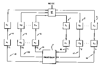
Figure 1 is a b~ock diagram showin~ the basic MIDVE system
Figure 2 is a block diagram detailin~ the impulse responses between the multipleinteracting inputs and outputs.
Figure 3A is a more detailed block diagram of an em~odiment of one ch~annel of
the input section of the MII~VE system of Figure I constructed in accordance with the
present invention used in the system of Figure 1.
Figure ~B is an alternate embodiment of the input channel detailed ;n Figure 3A.Figure 4A is a more detailed block diagram of an embodiment of one channel of
10 the output section of the MIDVE system of Figure I constructed in accordance with the
present invention used in the system of Figure 1.
Figure 4B is an alternate embodiment of the output channel detailed in Figure 4A.
Figure 5 is a depiction of how Figures SA and 5B are joined to form a single
block diagram.
Figures 5A and 5B are block diagrams showing the partial operation of an
embodiment of the processor constructed in accordance with the present invention used
in the system of Figure 1
.
DETAILED DESCRlPTION
Figure I is a block diagram which depicts the basic composition of a MID~
system. For the remainder of the context of this discussion, only 3 channels of the
MIDVE system will be diagrammed. The last, channel "n", should be understood to
represent the nth channel of an n-channel system. So, the system is made up of residual
sensors 1, 2, and 3, actuators 4, 5, and 6, and a processor 7 The system functions as
follows. Phenomena (e.g. noise and/or vibration) are received by the multiple residual
sensors 1, 2 and 3. In response, these sensors emit their respective sensor signals. These
sensor signals are affected by Yarious system factors which have impulse responses El,
- E2,.. , and En The resulting residual signals rl, r2,.. , and rn (16, 17, and 18) are
received by the processor 7 which it uses to generate the cancellation signals Yl. Y2, .
and Yn (19, 20, and 21). These cancellation si~nals are affected ~y various factors which
have impulse responses Sl, S2,.. , and Sn. The resulting cancellation output
phenomena from the actuators 4, 5, and 6 combines with the original phenomena, and the
residual is detected by the residual sensors 1, 2, and 3.
The signal values are determined by
NS~ FA~
Ya,k=- ~ ~ As,a,m,k ~s,k-m
s=O ",=,~
AMENtK~ SHE~
21~201~ n~r,!~S~2~0765?
IpE~ius O 5 ~JG t994
where
Ya. k is the cancel]ation signal ~rom actuator a at time k
x5, k - m is the ~alue of the estimated noise signal at sensor s at time k - m
and
As a m k is the m~h coefficient at time k of the cancellation filter associated
with sensor s and actuator a.
Figure 2 is a block diagram showing all of the paths of the impulse responses
between the multiple inputs and outputs of the system. At each sensor, the output of
each actuator has been affected by the impulse response between that sensor and the
0 respective actuator The designations C 1 1 through Cn 3 denote the vectors of
coefficients of the impulse responses (from the controller output to the error sensor
input) from actuator al to sensor S I and so on through actuator an to sensor Sn . The
term Ca 5 is a general term, the specific terms Cl 1, etc., are enumerated instead of
general. Each one is an instance of th~ variables of the general term Ca s The C's
1~ shown in Figure S are estimates of physical actual values shown in Figure 2, this is
obvious from the text. In Figure 2 the C's are actual values and in Figure 5 they are
estimates as are all of the equations estimates.
Figures 3A and 3B are more detailed block diagrams of the input section of the
MIDVE system. The residual sensors 1, 2, and 3 detect the noise and/or vibrationphenomena and in response emit sensor signals 8, 9, and 10. Each of these signals pass
through an amplifier/gain stage 11, and are then conditioned by anti-aliasing circuitry 12.
These conditioned signals are then sampled and converted to digital signals through the
combination of the sample-and-hold circuitry 13 and the analog-to-digital converter
(A/D), 14. Note that, although described pictorially as a separate entity, the sample-and
-hold circuitry could be part of 14. In addition, note that the multiple input signals could
be multiplexed 1 S through one set of input conditioning circuitry (Figure 3A) or each
could have its own set of dedicated input circuitry (Figure 3B). In Figure 3B, the
additional circuitry required would consist of additional amplifier/gain control stages 22
and 23, additional anti-aliasing filters 24 and 25, additional sample-and-hold circuitry 26
and 27, and additional A/D's 28 and 29. The resulting digital input values, the residual
signals rl, r2, and rn (16, 17, and 18), are then available for use by the processor 7. The
processor consumes the input data values and from them produces the appropriate
cancellation output signal. Other embodiments of the input electronic circuitry could be
used in place of that described above and shown in Figure 3B in order to pro~ide the
input data.
Figures 4A and 4B are more detailed dial~rams of the output section of the
MIDVE system. The residual signals rl r~, dnd rn (16, 17, and 18) from the inputsection are used by the processor, along w,th the system impulse response, to produce
AA'~EH~E~ SIlEtT
~,
2142014 ~TIilS 92/ 37 65 O ~-
IPE~l~'S b 5 ~u G l994
the appropriate cancellation signals Yl. Y2. and Yn (19 20, and 21). The cancellation
signals are converted to analog form by the digital-to-analog converter 31. These analog
signals then pass through a reconstruction filter 32, are amplified by a gain stage 33, and
are then converted to physical phenomena by actuator 34. The resulting cancellation
phenomena mixes with the original noise/vibration phenomena and the residual is
detected by residual sensors 1, 2, and 3 in the input section of the system. Note that the
multipl~ ~ utput signals could be multiplexed, as at 30, through one set of output circuitry
(Figure 4A) or each could have its o~n set of dedicated input circuitry (Figure 4~) In
Figure 4B, the additional circuitry required would consist of additional D/A's 35 and 36,
0 additional reconstruction filters 37 and 38, additional amplifier/gain stages 39 and 40, and
additional actuators 41 and 42. In the MIDVE system, the system impulse response for
any given OUtp~lt section includes the impulse response S of the respective output
circuitry 31, 32, 33, 34, and another configuration, if desired, and the impulse responses
El, E2,...., and En of the input circuitry 11,12, 13, 14, (if so configured) of each of the
multiple input sections. Thus, each input channel of the system has an effect on the
output of each channel.
Figure 5, comprising Figures 5A and 5B, is a block diagram showing the partial
operation of an embodiment-of the processor 7 constructed in accordance with thepresent invention used in the system of Figure 1. The processor 7 receives the residual
signals rl, r2, and rn (16, 17, and 18) from the multiple sensors. The MIDVE algorithm
estimates the noise at each sensor by subtracting out the combined effects of each
actuator signal from the residual signal as follows:
NA-I NG.s-l
Xs~k=es~k- ~ ~ Ca,s,l Ya,k-l
a=O 1=0
where the subscripts a and s denote the actuator and sensor, and the subscript k denotes the value at sample time k. The estimates xl, x2, and xn (52, 53, and 54) of the
noise at each sensor proceed from their respective sllmm~tion points, through delay lines
55, 56, and 57, and each are input to adaptive filters 64, 65, and 66. The output of the
adaptive filters, each having filter weights Am n~ are summed, then inverted, and the
resulting signal is output to the output circuitry. Thus, the processor computes the
cancellation signal for each actuator as follows:
NS-I NFA~
Ya,k=~~ ~ As,a,m,k Xs,k-m
s=O m=O
The output delay lines 55, 56, and 57 are also provided to a second set of filter~
143, 144, and 145 that are a model of the impulse response between the respective
~M~N~ED S~EET
2142014 pr~US 9~/ 07 65 0
11~ A IJS~ ~U G 1994
sensor and actuator The output from these filters proceed through another set of delay
lines 58, 59, and 60, and are then used by adapters 61, 62, and 63. These adapters use
the filtered outputs, along with the original residual signals rl, r2, and rn, to provide
adaptation signals to the adaptive filters 64, 65, and 66. These adaptation signals are
5 used to adjust the adaptive filter weights Am n The cancellation filter coefficients are
updated using a multidimensional filtered-x algorithm as follows:
.~c- I
ga,s,k= ~ Ca,s,l Xs,k-l
,=o
As,a,m,lc+l =As~a~m~k+aeskGasmlc
The diagram of Figures 5A and 5B show the operations that the processor
performs in calculating the output for channel I of the MIDVE system, but would be
similarly extended for all other output channels.
The processor 7 depicted in Figures SA and SB could be implemented in any of
15 several forms including fixed program hardware, custom VLSI, or in one or more stored
program microprocessors.
Although the present invention has been described and illustrated in detail, it is to
be clearly understood that the same is by way of illustration and example only. In no way
should it be talcen by way of limitation. The spirit and scope of the present invention are
20 to be limited only by the terms Of the following claims in which I claim:
~MtN.iED 5~