Sélection de la langue

Search

Sommaire du brevet 2142893 

Énoncé de désistement de responsabilité concernant l'information provenant de tiers

Une partie des informations de ce site Web a été fournie par des sources externes. Le gouvernement du Canada n'assume aucune responsabilité concernant la précision, l'actualité ou la fiabilité des informations fournies par les sources externes. Les utilisateurs qui désirent employer cette information devraient consulter directement la source des informations. Le contenu fourni par les sources externes n'est pas assujetti aux exigences sur les langues officielles, la protection des renseignements personnels et l'accessibilité.

Disponibilité de l'Abrégé et des Revendications

L'apparition de différences dans le texte et l'image des Revendications et de l'Abrégé dépend du moment auquel le document est publié. Les textes des Revendications et de l'Abrégé sont affichés :

  • lorsque la demande peut être examinée par le public;
  • lorsque le brevet est émis (délivrance).
(12) Brevet: (11) CA 2142893
(54) Titre français: METHODE DE CHARGE DE SOLIDES DANS UN METAL EN FUSION
(54) Titre anglais: CHARGING METAL SOLIDS INTO MOLTEN METAL
Statut: Durée expirée - au-delà du délai suivant l'octroi
Données bibliographiques
(51) Classification internationale des brevets (CIB):
  • C22B 7/00 (2006.01)
  • C22B 21/00 (2006.01)
  • F27D 3/00 (2006.01)
  • F27D 3/14 (2006.01)
(72) Inventeurs :
  • BROWN, WARWICK NICHOLSON (Royaume-Uni)
  • HOWITT, ROGER (Royaume-Uni)
  • KATYAL, ANIL (Royaume-Uni)
(73) Titulaires :
  • CALDER ALUMINIUM LIMITED
(71) Demandeurs :
  • CALDER ALUMINIUM LIMITED (Royaume-Uni)
(74) Agent: SMART & BIGGAR LP
(74) Co-agent:
(45) Délivré: 2004-11-09
(86) Date de dépôt PCT: 1993-08-18
(87) Mise à la disponibilité du public: 1994-03-03
Requête d'examen: 2000-08-04
Licence disponible: S.O.
Cédé au domaine public: S.O.
(25) Langue des documents déposés: Anglais

Traité de coopération en matière de brevets (PCT): Oui
(86) Numéro de la demande PCT: PCT/GB1993/001747
(87) Numéro de publication internationale PCT: WO 1994004711
(85) Entrée nationale: 1995-02-20

(30) Données de priorité de la demande:
Numéro de la demande Pays / territoire Date
9217802.9 (Royaume-Uni) 1992-08-21

Abrégés

Abrégé anglais


A furnace (1) has a main holding portion (2) and a charging well (4) into
which molten metal from the holding portion is
circulated by means of an electromagnetic pump (7). Metal enters the well as a
tangential flow and a stationary turbulator (10) is
located in the path of the flow so as to upwardly and transversely deflect the
flow. Resulting turbulence within the well enhances
the rate of assimilation of solids into the metal without resulting in
excessive oxidation. The method is suitable for melting
aluminium swarf.

Revendications

Note : Les revendications sont présentées dans la langue officielle dans laquelle elles ont été soumises.


-11-
CLAIMS:
1. A method of charging metal solids into a body of molten
metal in a furnace comprising the step of heating a body of
molten metal in a holding portion of the furnace,
transferring metal from the holding portion to a well annexed
to the holding portion such that a flow of metal enters the
well beneath the surface of metal in the well, feeding the
metal solids into contact with the surface of molten metal in
the well and returning molten metal from the well into the
holding portion, the method including the step of creating
turbulence in the flow within the well by means of a
stationary turbulator located in the path of the flow and
wherein the turbulator deflects the flow by means of at least
a first deflecting surface which is upwardly inclined so as
to impart to the flow at least a component of motion in an
upward direction.
2. A method as claimed in claim 1 wherein the first
deflecting surface is also laterally inclined whereby the
first deflecting surface deflects the flow so as to impart to
the flow a horizontal component of motion.
3. A method as claimed in claim 1 or claim 2 wherein the
turbulator further deflects the flow by means of a second
deflecting surface located downstream of the first reflecting
surface with respect to the flow and which is more steeply
inclined to the horizontal than the first deflecting surface.
4. A method as claimed in any one of claims 1 to 3 in which
the metal is transferred into the well through an inlet so as
to enter the well tangentially relative to an internal
cylindrical wall of the well.
5. A method as claimed in claim 4 wherein the metal flows
into the well from the inlet conduit through an inlet
aperture located immediately adjacent to a floor of the well.

-12-
6. A method as claimed in claim 5 including the step of
collecting surface dross at a location upstream of the inlet
aperture with respect to the direction of flow by means of a
baffle projecting inwardly of the cylindrical internal wall
of the well.
7. A method as claimed in any one of the preceding claims 1
to 6 wherein metal is transferred between the holding portion
and the well by means of an electromagnetic pump.
8. Apparatus for charging metal solids into a body of
molten metal in a furnace comprising a well annexed to a
holding portion of the furnace, heating means operable to
heat molten metal in the holding portion, transferral means
operable to transfer metal between the holding portion and
the well such that in use a flow of metal enters the well
beneath the surface of the metal in the well via an inlet
conduit, means for feeding metal solids into contact with the
surface of molten metal in the well and returning means for
returning molten metal from the well to the holding portion,
wherein the well further comprises a turbulator located in
the path of the flow of molten metal in the well and wherein
the turbulator comprises at least a first upwardly inclined
deflecting surface arranged to impart to the flow at least an
upward component of motion.
9. Apparatus as claimed in claim 8 wherein the first
deflecting surface is laterally inclined so as to impart to
the flow a horizontal component of motion.
10. Apparatus as claimed in claim 8 or 9 wherein the
turbulator comprises a second deflecting surface located
downstream of the first deflecting surface with respect to
the flow and which is more steeply inclined to the horizontal
than the first surface.

-13-
11. Apparatus as claimed in any one of claims 8 to 10
wherein the well comprises a cylindrical internal surface
extending upwardly from a floor and wherein the first
deflecting surface intersects the floor and the cylindrical
surface so as to obliquely truncate the internal cylindrical
volume of the well.
12. Apparatus as claimed in any one of claims 8 to 11
wherein the inlet conduit extends non-radially with respect
to the cylindrical internal surface of the well so that in
use the transfer of metal into the well creates a flow which
enters tangentially.
13. Apparatus as claimed in claim 12 wherein the inlet
conduit communicates with the well through an inlet aperture
located immediately adjacent to the floor of the well.
14. Apparatus as claimed in claim 13 wherein the well
comprises a baffle projecting inwardly of the cylindrical
internal surface of the well at a location upstream of the
inlet aperture with respect to the direction of flow, the
baffle projecting upwardly above the surface of molten metal
to define an area as the surface in which surface dross is
collected in use.
15. Apparatus as claimed in any one of claims 8 to 14
wherein the turbulator comprises a refractory block mounted
on an internal surface of the well and defining at least one
deflecting surface which is stationary relative to the
internal surface.
16. Apparatus as claimed in any one of claims 8 to 15
wherein the transferral means comprises an electromagnetic
pump.
17. Apparatus as claimed in any one of claims 8 to 16
comprising an outlet conduit connected to the well downstream

-14-
of the turbulator and communicating with the holding portion
for returning molten metal.
18. A method of charging metal solids into a body of molten
metal comprising the step of circulating the molten metal
within a charging well to create a vortical flow of molten
metal, deflecting the flow upwardly towards a liquid surface
of the molten metal by means of a stationary deflecting
surface located in the path of the flow and feeding the metal
solids into contact with the liquid surface.
19. A method of charging metal solids into a body of molten
metal in a furnace comprising the step of heating a body of
molten metal in a holding portion of the furnace,
transferring metal from the holding portion to a well annexed
to the holding portion such that a flow of metal enters the
well beneath the surface of metal in the well, feeding the
metal solids into contact with the surface of molten metal in
the well and returning molten metal from the well into the
holding portion, the method including the step of creating
turbulence in the flow within the well by means of a
stationary turbulator located in the path of the flow,
wherein the turbulator deflects the flow by means of a first
deflecting surface which is upwardly inclined so as to impart
to the flow at least a component of motion in an upward
directions and wherein the turbulator further deflects the
flow by means of a second deflecting surface located
downstream of the first deflecting surface with respect to
the flow and which is more steeply inclined to the horizontal
than the first deflecting surface.
20. Apparatus for charging metal solids into a body of
molten metal in a furnace comprising a well annexed to a
holding portion of the furnace, heating means operable to
heat molten metal in the holding portion, transferral means
operable to transfer metal between the holding portion and
the well such that in use a flow of metal enters the well

-15-
beneath the surface of the metal in the well via an inlet
conduit, means for feeding metal solids into contact with the
surface of molten metal in the well and returning means for
returning molten metal from the well to the holding portion,
further comprises a turbulator located in the path of the
flow of molten metal in the well, wherein the turbulator
comprises a first upwardly inclined deflecting surface
arranged to impart to the flow at least an upward component
of motion, and wherein the turbulator comprises a second
deflecting surface located downstream of the first deflecting
surface with respect, too the flow and which is more steeply
inclined to the horizontal than the first surface.

Description

Note : Les descriptions sont présentées dans la langue officielle dans laquelle elles ont été soumises.

WO 94J04711 - ~ ~ ~ ~ ~ ~ PCT/GB93/01747
- 1 -
CHARGING METAL SOLIDS INTO MOLTEN METAL
This invention relates to a furnace and to a
method of melting metal solids in a furnace, and in
particular but not exclusively to a method of charging
aluminium swarf in a furnace.
The charging of metal solids into a furnace in a
manner which is both efficient and environmentally
acceptable presents particular difficulties when the
metal solids to be charged are in the form of finely
divided aluminium scrap such as industrial swarf
having a relatively large surface area. The surface
oxide layer on the aluminium solids is resistant to
incorporation of the solids into a body of molten
metal and creates surface dross which must be
separated and removed.
It is known to provide a holding portion of a
furnace in which a body of molten metal is heated
within an enclosure within which controlled combustion
inhibits oxidisation of the molten metal. Metal
solids are introduced in a well annexed to the holding
portion of the furnace and molten metal is transferred
between the holding portion and the well in order to
both maintain the temperature of metal in the well and
to deliver fresh metal to the holding portion.
It is also known from US 4884786 to provide for
mechanical stirring of the molten metal within the
well in order to assist the rate of assimilation of
solids into the liquid phase within the well. Such
stirring however has the disadvantage of enhancing the
rate at which molten metal within the well is oxidised
by contact with air. The stirring operation is itself
problematic in that the stirring implements must be
formed of materials capable of withstanding the
required operating temperature which materials tend to
be brittle and therefore require frequent replacement.

WO 94104711 PCT/GB93/01747
214~~93 - 2 -
It is also known from GB-2072819-A to avoid the
need for stirring implements by supplying pumped metal
to the well through a tangential channel to create a
vortex and to disrupt the vortex by a further flow
from radial channel entering the well at a lower
level. A resulting roll-over effect is said to aid
ingestion. The elevated level at which the tangential
channel pours metal into the well is however~likely to
result in a pouring effect which will enhance the rate
of oxidation. The use of alternative melting media
such as molton salt reduces the rate of oxidation but
has the disadvantage that the subsequent disposal of
such media in an environmentally acceptable manner is
costly.
According to the present invention there is
disclosed a method of charging metal solids into a
body of molten metal in a furnace comprising the step
of heating a body of molten metal in a holding portion
of the furnace, transferring metal from the holding
portion to a well annexed to the holding portion such
that a flow of metal enters the well beneath the
surface of metal in the well, feeding the metal solids
into contact with the surface of molten metal in the
well and returning molten metal from the well into the
holding portion, the method including the step of
creating turbulence in the flow within the well by
means of a stationary turbulator located in the path
of the f low.
An advantage of such a method is that the
resulting turbulence tends to speed up the process of
assimilation of the metal solids into the liquid phase
without resulting in unacceptable levels of oxidation.
Preferably the turbulator deflects the flow by
means of at least a first deflecting surface so as to
impart at least a component of motion in an upward
direction.

WO 94/04711 _ 214 2 8 9 3 , , p~/GB93/01747
- 3 -
Agitation of the surface by ripples is observed
to occur in the presence of such a turbulator and this
is indicative of there being turbulence in the metal
near the surface. The surface 3isturbance is believed
to assist the process of introducing metal solids into
the liquid phase. The extent to which the surface is
disrupted is however insufficient to cause excessive
oxidation.
Preferably the first deflecting surface also
deflects the flow so as to impart a horizontal
component of motion.
Preferably the turbulator further deflects the
flow by means of a second deflecting surface located
downstream of the first deflecting surface with
respect to the flow and which is more steeply inclined
to the horizontal than the first deflecting surface.
Conveniently the metal is transferred into the
well so as to enter the well through an inlet conduit
tangentially relative to an internal cylindrical wall
of the well to thereby establish circumferential
circulation.
This circulation assists mixing of the metal
within the well to maintain an even temperature.
Preferably the metal flows into the well from
the inlet conduit through an inlet aperture located
immediately adjacent to a floor of the well. In a
preferred embodiment the well has a cylindrical
internal surface with a horizontal floor.
Preferably the method includes the step of
collecting surface dross at a location upstream of the
inlet aperture with respect to the flow by means of a
baffle projecting inwardly of the cylindrical internal
wall of the well.
Conveniently metal is transferred from c.he
holding portion to the well by means of an
electromagnetic pump.

WO 94/04711 214 2 8 9 3 P~/GB93/01747
- - 4 -
The method has particular application to the
charging of aluminium swarf.
According to a further aspect of the present
invention there is disclosed apparatus for charging
metal solids into a body of molten metal in a furnace
comprising a well annexed to a holding portion of the
furnace, heating means operable to heat molten metal
in the holding portion, transferral means~operable to
transfer metal through an inlet conduit ~o the well
such that a flow of metal enters the well beneath the
surface of the metal in the well, returning means for
returning molten metal from the well to the holding
portion and means for feeding metal solids into
contact with the surface of molten metal in the well
wherein the well further comprises a turbulator
located in the path of the flow of molten metal in the
well.
Preferably the turbulator comprises at least a
first upwardly inclined deflecting surface arranged to
impart to the flow at least an upward component of
motion to thereby cause agitation of the surface of
molten metal.
Advantageously the first deflecting surface is
laterally inclined so as to impart to the flow a
horizontal component of motion.
Advantageously the turbulator comprises a second
deflecting surface located downstream of the first
deflecting surface and which is more steeply inclined
than the first surface.
An advantage of such an arrangement is to
provide enhanced turbulence by progressively
deflecting the flow.
Advantageously the inlet conduit communicates
with the well through are inelt aperture located
immediately adjacent to the floor of the well.
This arrangement avoids having the metal poured

2142893
WO 94/04711 - . PCT/GB93/01747
- 5 -
into the well in a manner likely to unnecessarily
increase the rate of oxidation, the inflow of metal
being at the bottom of the well.
Preferably the turbulator comprises a refractory
block mounted on an internal surface of the well and
defining at least one deflecting surface which is
stationary relative to the internal surface.
Such a turbulator thereby achieves turbulence in
a controlled manner without involving any moving parts
within the well.
Advantageously the apparatus comprises a baffle
projecting inwardly of the cylindrical internal
surface of the well at a location upstream of the
inlet conduit with respect to the circumferential
flow, the baffle projecting upwardly above the surface
of molten metal to define an area of the surface in
which surface dross is collected in use.
Conveniently the apparatus comprises an
electromagnetic pump connected between the holding
portion and the inlet conduit.
Embodiments of the present invention will now be
disclosed by way of example only and with reference to
the accompanying drawings of which:
Figure 1 is a schematic plan view of an empty
furnace constructed in accordance with the present
invention;
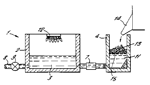
Figure 2 is a schematic sectional elevation of
the furnace of Figure 1 when partially filled;
Figure 3 is a sectional plan view of the well of
the furnace of Figures 1 and 2;
Figure 4 is a vertical section of the well of
Figure 3 taken at IV-IV;
Figure 5 is a plan view of a well of a second
embodiment of the present invention;
Figure 6 is a staggered sectional elevation of
the well of Figure 5 taken at VI-VI;

WO 94/04711 PCT/GB93/01747
214289 -
6 -
Figure 7 is a plan view of a well of a third
embodiment of the present invention when empty;
Figure 8 is a vertical section of the well of
Figure 7 taken at VIII-VIII; and
Figure 9 is a further vertical section of the
well of Figure 7 when empty taken at IX-IX.
In Figures 1 and 2 a furnace 1 comprises a
holding portion 2 containing a main body of molten
metal 3 (not shown in Figure 1). A well 4 is annexed
to the holding portion 2 with which it communicates
via an inlet conduit 5 and an outlet conduit 6.
The inlet conduit 5 is provided with an
electromagnetic pump 7 operable to impel metal in a
direction from the holding portion 2 towards the well
4.
The holding portion 2 is provided with an outlet
8 regulated by an outlet valve 9.
A stationary turbulator 10 is located in the
well and is submerged beneath a body 11 of molten
metal within the well.
As seen in Figure 2 the holding portion 2 is
provided with a gas burner 12 providing heat within
the holding portion in the manner of a reverberatory
furnace in which oxidisation of the main body of
molten metal 3 is substantially prevented by
controlled combustion provided by the gas burner.
Metal solids 13 in the form of swarf are
deposited in the well 4 from a hopper 14 and an
accumulation of metal solids rests in contact with a
liquid surface 15 of the body of molten metal 11
within the well 4.
As shown in Figures 3 and 4 the well has an
upright cylindrical internal surface 16 with a
horizontal floor 17. In these Figures the :~et~l
solids 13 shown in Figure 2 are omitted for clarity.
The inlet conduit 5 communicates with the well via an

WO 94/04711 _ 214 2 x 9 3 PCT/GB93/01747
inlet aperture 18 formed in the cylindrical internal
surface 16 at a location which is immediately adjacent
to the floor 17. The inlet conduit 5 defines a
cylindrical bore 19 which extends horizontally and
linearly such that the bore merges tangentially with
the cylindrical internal surface 16. Molten metal
impelled by the pump 7 is therefore directed into the
well 4 so as to create a tangential flow indicated by
arrow A in Figure 3. The flow A enters the well 4
beneath the liquid surface 15 and tends to set up a
circulating liquid flow within the well in an
anti-clockwise direction as viewed in Figure 3.
The turbulator 10 is located directly in the
path of the flow A. The turbulator 10 consists of a
moulded refractory block having a planar face 21
contacted by the body 11 of molten metal within the
well, the face being inclined at an angle of 32° to
the horizontal and intersecting both the floor 17 and
the cylindrical surface 16 so as to obliquely truncate
the internal cylindrical volume of the well.
As seen in Figure 3 the face 21 is oriented such
that in vertical projection the face is inclined at
45° to the flow A, and as shown in Figure 4, when
viewed in horizontal projection at right angles to the
bore 19 the face 21 of the turbulator is upwardly
inclined at 320.
The effect of the turbulator 10 on the flow A is
to impart both vertical and horizontal components of
motion to the flow thereby disrupting the flow and
creating turbulence. This turbulence results in
ripples being formed on the surface 15 and vortical
movement adjacent the surface.
As shown in Figure 3 the outlet conduit 6
defines an outlet bore c2 which extends tangentially
with respect to the cylindrical internal surface 16 in
a direction such that the circulating flow urges

WO 94/04711 PCT/GB93/01747
8_
214289 _
molten metal through the bore to return into the main
body of molten metal 3.
Metal solids 13 in contact with the surface 15
are heated by contact with the body of molten metal 11
within the well and are progressively assimilated into
the liquid body. The oxide layer from the metal
solids 13 is shed to form surface~dross (not shown)
which can be collected and removed at the end of
melting a batch of metal solids.
The turbulence created within the body of molten
metal 11 by the turbulator 10 has been found to speed
up the process of assimilation of the metal solids
into the liquid phase and this is believed to be
partly due to the effect of agitation caused by the
ripples on the liquid surface and partly due to the
sheering effect of turbulence within the body of
liquid assisting the separation of oxide layer from
the metal.
A modified furnace will now be described with
reference to Figures 5 and 6 using reference numerals
corresponding to those of previous Figures where
appropriate for corresponding elements.
The modified furnace of Figures 5 and 6 has a
holding portion 2 corresponding to that of Figure 1
and a well 30 as shown in the Figures.
The well 30 includes a turbulator 10 and also a
baffle 31 which projects inwardly of the internal
cylindrical surface 16 at a location immediately
adjacent the inlet aperture 18. The baffle 31 is
positioned upstream of the inlet aperture 18 with
respect to the anti-clockwise circulating flow within
the well 4 and is intermediate the inlet and outlet
conduits 5 and 6.
ii~e baffle 31 is formed of a moulded refractory
material and is shaped so as to have mutually
orthogonal vertically extending first and second faces

_ 2i4z~~3
WO 94/04711 PCT/GB93/01747
_ g _
32 and 33 which are symmetrically disposed about an
imaginary plane extending radially from the
cylindrical axis of the well 30.
The first vertical face 32 projects obliquely
into the circumferential flow indicated by arrow B in
Figure 5 and projects upwardly above the molten metal
surface 15. Dross floating on the surface 15 tends
to accumulate in an area of the surface 15 immediately
upstream of the first vertical face 32 with respect to
the flow B and the accumulated dross is removed at the
end of processing a batch of metal solids.
A further alternative furnace will now be
described with reference to Figures 7, 8 and 9 using
corresponding reference numerals to those of preceding
Figures where appropriate for corresponding elements.
The furnace shown in Figures 7, 8 and 9 has a
modified well 40 having a turbulator 10 with first and
second planar surfaces 41 and 42 respectively which
are inclined at 32° and 55° respectively to the
horizontal. The first and second planar surfaces 41
and 42 a.re connected by a triangular surface portion
43 which is shaped so as to merge smoothly with each
of these respective surfaces.
The first planar surface 41 is located in the
path of the flow A emerging from the inlet aperture 18
so as to tend to divert the flow A in both upward and
radially inward directions.
The first planar surface 41 intersects the floor
17 in a line of intersection 44 which extends at an
angle of about 75° to the flow A. The second
planar surface 42 intersects the floor 17 co-linearly
with the line of intersection 44 such that the
surfaces 41 and 42 are joined together at a point of
intersection 45.
The flow A encounters the first planar surface
41 of the turbulator 10, then encounters the more

WO 94/04711 PCT/GB93/01747
-
214293 _
steeply inclined triangular surface portion 43 and
finally encounters the second planar surface 42. The
complex gradient profile provided by the turbulator 10
in the furnace of Figures 7 to 9 thereby is thc::yht to
5 create more pronounced and disruptive turbulence in
the flow compared with the turbulators of preceding
Figures.
Alternative embodiments of. the present invention
are envisaged in which for example the electromagnetic
10 pump is replaced by a mechanical impeller pump.
The method of heating metal in the holding
portion may be other than by gas combustion and may
for example comprise inductive heating. The method
and apparatus of the present invention may be utilised
for processing metal solids other than swarf. Finely
divided solids such as obtained from recycling
processes also present similar difficulties when
charging into a furnace and the present method and
apparatus similarly provides the above advantages.
Larger metal solids may also be added to the
well if required and typically will be fed into the
well at the end of a batch during which more finely
divided solids are initially charged.
The present method and apparatus may have
application to metals other than aluminium.
The method and apparatus of the present
invention may also be used in a metal refining process.
35

Dessin représentatif
Une figure unique qui représente un dessin illustrant l'invention.
États administratifs

2024-08-01 : Dans le cadre de la transition vers les Brevets de nouvelle génération (BNG), la base de données sur les brevets canadiens (BDBC) contient désormais un Historique d'événement plus détaillé, qui reproduit le Journal des événements de notre nouvelle solution interne.

Veuillez noter que les événements débutant par « Inactive : » se réfèrent à des événements qui ne sont plus utilisés dans notre nouvelle solution interne.

Pour une meilleure compréhension de l'état de la demande ou brevet qui figure sur cette page, la rubrique Mise en garde , et les descriptions de Brevet , Historique d'événement , Taxes périodiques et Historique des paiements devraient être consultées.

Historique d'événement

Description Date
Inactive : Périmé (brevet - nouvelle loi) 2013-08-18
Inactive : CIB de MCD 2006-03-11
Accordé par délivrance 2004-11-09
Inactive : Page couverture publiée 2004-11-08
Inactive : Taxe finale reçue 2004-07-27
Préoctroi 2004-07-27
Un avis d'acceptation est envoyé 2004-03-31
Lettre envoyée 2004-03-31
Un avis d'acceptation est envoyé 2004-03-31
Inactive : Approuvée aux fins d'acceptation (AFA) 2004-03-23
Modification reçue - modification volontaire 2003-07-21
Inactive : Dem. de l'examinateur par.30(2) Règles 2003-01-21
Modification reçue - modification volontaire 2000-10-27
Inactive : Dem. traitée sur TS dès date d'ent. journal 2000-08-22
Lettre envoyée 2000-08-22
Inactive : Renseign. sur l'état - Complets dès date d'ent. journ. 2000-08-22
Exigences pour une requête d'examen - jugée conforme 2000-08-04
Toutes les exigences pour l'examen - jugée conforme 2000-08-04
Exigences pour l'entrée dans la phase nationale - jugée conforme 1995-02-20
Demande publiée (accessible au public) 1994-03-03

Historique d'abandonnement

Il n'y a pas d'historique d'abandonnement

Taxes périodiques

Le dernier paiement a été reçu le 2004-08-16

Avis : Si le paiement en totalité n'a pas été reçu au plus tard à la date indiquée, une taxe supplémentaire peut être imposée, soit une des taxes suivantes :

  • taxe de rétablissement ;
  • taxe pour paiement en souffrance ; ou
  • taxe additionnelle pour le renversement d'une péremption réputée.

Veuillez vous référer à la page web des taxes sur les brevets de l'OPIC pour voir tous les montants actuels des taxes.

Historique des taxes

Type de taxes Anniversaire Échéance Date payée
TM (demande, 4e anniv.) - générale 04 1997-08-18 1997-06-06
TM (demande, 5e anniv.) - générale 05 1998-08-18 1998-08-05
TM (demande, 6e anniv.) - générale 06 1999-08-18 1999-06-07
TM (demande, 7e anniv.) - générale 07 2000-08-18 2000-08-01
Requête d'examen - générale 2000-08-04
TM (demande, 8e anniv.) - générale 08 2001-08-20 2001-08-10
TM (demande, 9e anniv.) - générale 09 2002-08-19 2002-07-02
TM (demande, 10e anniv.) - générale 10 2003-08-18 2003-08-18
Taxe finale - générale 2004-07-27
TM (demande, 11e anniv.) - générale 11 2004-08-18 2004-08-16
TM (brevet, 12e anniv.) - générale 2005-08-18 2005-07-08
TM (brevet, 13e anniv.) - générale 2006-08-18 2006-07-07
TM (brevet, 14e anniv.) - générale 2007-08-20 2007-07-19
TM (brevet, 15e anniv.) - générale 2008-08-18 2008-07-18
TM (brevet, 16e anniv.) - générale 2009-08-18 2009-07-16
TM (brevet, 17e anniv.) - générale 2010-08-18 2010-07-16
TM (brevet, 18e anniv.) - générale 2011-08-18 2011-07-22
TM (brevet, 19e anniv.) - générale 2012-08-20 2012-07-27
Titulaires au dossier

Les titulaires actuels et antérieures au dossier sont affichés en ordre alphabétique.

Titulaires actuels au dossier
CALDER ALUMINIUM LIMITED
Titulaires antérieures au dossier
ANIL KATYAL
ROGER HOWITT
WARWICK NICHOLSON BROWN
Les propriétaires antérieurs qui ne figurent pas dans la liste des « Propriétaires au dossier » apparaîtront dans d'autres documents au dossier.
Documents

Pour visionner les fichiers sélectionnés, entrer le code reCAPTCHA :


Pour visualiser une image, cliquer sur un lien dans la colonne description du document. Pour télécharger l'image (les images), cliquer l'une ou plusieurs cases à cocher dans la première colonne et ensuite cliquer sur le bouton "Télécharger sélection en format PDF (archive Zip)" ou le bouton "Télécharger sélection (en un fichier PDF fusionné)".

Liste des documents de brevet publiés et non publiés sur la BDBC .

Si vous avez des difficultés à accéder au contenu, veuillez communiquer avec le Centre de services à la clientèle au 1-866-997-1936, ou envoyer un courriel au Centre de service à la clientèle de l'OPIC.


Description du
Document 
Date
(aaaa-mm-jj) 
Nombre de pages   Taille de l'image (Ko) 
Dessin représentatif 1998-01-20 1 10
Revendications 2003-07-21 5 204
Description 1995-10-28 10 424
Dessins 1995-10-28 5 97
Revendications 1995-10-28 5 157
Page couverture 1995-10-28 1 22
Abrégé 1995-10-28 1 53
Dessin représentatif 2004-03-24 1 9
Page couverture 2004-10-06 1 40
Rappel - requête d'examen 2000-04-19 1 117
Accusé de réception de la requête d'examen 2000-08-22 1 178
Avis du commissaire - Demande jugée acceptable 2004-03-31 1 161
PCT 1995-02-20 11 405
Taxes 2003-08-18 2 65
Taxes 2000-08-01 1 32
Taxes 2001-08-10 1 34
Taxes 1997-06-06 1 33
Taxes 2002-07-02 1 34
Taxes 1998-08-05 1 36
Taxes 1999-06-07 1 27
Correspondance 2004-07-27 1 30
Taxes 2004-08-16 1 35
Taxes 1996-07-04 1 32
Taxes 1995-06-05 1 43