Note : Les descriptions sont présentées dans la langue officielle dans laquelle elles ont été soumises.
WO 94/06192 ~ PCT/US93/08200
-1-
STATOR AND METHOD OF CONSTRUCTING SAME
FOR HIGH POWER DENSITY ELECTRIC MOTORS AND GENERATORS
Field of Invention
This invention relates to a stator or armature for brushless do electric
motors and generators. The stator or armature is constructed from a plurality
of
segments that carry the windings and which are assembled in a cylindrical
shape.
This technology is highly suited for machines with a high pole count which
requires a large number of teeth. This motor design will result in a high
power
density electro-mechanical transducer.
Background of the Invention:
The vast majority of conventional electric motors have stator cores
constructed from sheets of laminated steel. The individual laminations are
punched from flat sheets of steel using specially constructed dies with the
necessary shape of slots and teeth incorporated in them. Laminations made by
this method are coated with a thin insulation layer, and then a plurality of
these
laminations are stacked together to form the complete laminated stator. The
construction of the stator core with the laminations separated by layers of
very
thin insulation is intended to control the iron losses experienced in the
stator.
These losses are a function of the thickness of the lamination and of the
material
WO 94/06192 PCT/US93/08200
-2-
used. This type of insulation technique could be considered to be on the
macroscopic level, implying that bulk volumes of material are insulated from
each
other by an electrically (but not magnetically) insulating layer. Other
parameters
affecting the iron losses are also important but are outside the scope of this
discussion. ,
A second but less widely used conventional construction typically involves
cold pressing raw metal powder into a "green" shape, followed by sintering the
product to improve its mechanical properties. It is well known that this
technology produces parts with minimal waste of material having good
dimensional tolerance (with very little machining required). It is also an
effective
method of reliably producing parts with complex geometry. Sintering such green
shapes, which involves diffusion between particles of controlled size and
properties, is typically accomplished at or less than the melting temperature
of
the material. Sintering increases mechanical strength, magnetic permeability
and,
unfortunately, iron losses. The increase in iron losses is so significant that
some
form of macroscopic insulation technique must be employed to control the
phenomenon within acceptable limits. The reason for the increase in iron
losses
during the sintering process is that diffusion, which occurs between the
particles,
increases their electrical continuity and eddy current losses.
In order to overcome this problem, Reen et al. (U.5. Patent 4,255,494)
cold presses powder metal into laminations having a thickness of between 0.008
and 0.150 inch. These "green" structures are then sintered to increase their
mechanical strength. Although these parts form complete annular structures,
several of these plate-like structures are stacked on top of each other and
fastened
together to make a stator. The individual particles are not insulated, however
electric insulation is provided (on the macroscopic level) by an insulating
layer
placed between the laminations.
In another approach, Horie et al. (U.S. Patent 4,719,377) describes the
production of a complete stator using powder and a resin in a process of cold
WO 94/06192 ~ ~ ~ ~ ~ PCT/US93/08200
-3-
compaction. In order to avoid the deterioration of the magnetic
characteristics,
the finished part is not sintered. The parts made by this method do not
possess
a high tensile strength. To improve the magnetic characteristics, by achieving
a
higher permeability and a higher saturation flux-density, inorganic powders
are
mixed in the resin. To decrease the high-frequency losses, a very small
quantity
of a coupling agent is added to the mixture before compaction.
Eddy current losses in the powdered iron core are caused by variations in
the magnetic field. Magnetic field variations are the result of rotation of a
rotor
(which has permanent magnets mounted on it), and changes in current passing
through the motor windings. It is well established that the reaction of iron
powder with phosphoric acid results in an iron phosphate coating on the
individual
particles which decreases the electrical continuity in the iron and reduces
the eddy
current losses. Subsequent sintering of these particles would destroy the
electrical
insulating properties of the phosphate coating.
Fisher (U.5. Pat. No. 5,004,944) assigned to the present assignee, uses
flux carrying elements comprised of "green" or cold pressed iron powder
containing a phosphate coating. Also disclosed is the use of "B" stage epoxy
and
wax as binders. Although electromagnetic properties have been acceptable,
mechanical properties of the material make it unsuitable for some structural
applications. The highest value of tensile strength achievable with cold
pressing
is about 2,000 lb/in2. This value is not high enough to practically enable
further
processing and handling of the product, and is certainly not high enough to
withstand the forces required for high power density motors. This shortcoming
in mechanical strength is compensated for by encapsulating or impregnating the
armature assembly with glass fiber reinforced epoxy, cast as a binding agent
between the windings and the iron powder bars. However, rigidity of the
structure is dependent on the elastic modulus of the epoxy. Depending on the
stator configuration, the relatively low elastic modulus of epoxy, in certain
WO 94/06192 PCT/US93/08200
-4-
circumstances, has potential for allowing undesirable deformations and dynamic
effects within the stator, caused by oscillatory electromagnetic forces.
It has recently become possible, as explained by Rutz et al (IT.S. Pat. No.
5,063,011) to use iron powder coated with a thermoplastic material, in
addition
to the phosphate layer. This product is referred to as . double coated iron.
Increased mechanical properties are attained by pressing the powder at a
temperature sufficiently high to melt the thermoplastic material, but not high
enough to allow large scale diffusion between the phosphate coated iron
particles.
In addition to the benefit of higher tensile strength, the volume of material
which
can be pressed is significantly larger when using the thermoplastic coated
powder.
In contrast to iron cores which are produced with a sintering process, the
electrical insulating properties that exist in iron cores produced with
particles
which are double coated can be considered to be microscopic. In other words,
each iron particle is adequately insulated from its adjacent particles. Eddy
current
losses are controlled on a microscopic level, rather than an a macroscopic
level.
Ward et al (U.S Pat. No. 4,947,065) describes an invention in which a
complete stator core is produced in one piece by pressing double coated
powdered
iron in a large mold. While this procedure makes it possible to avoid punching
thin individual laminations and then stacking them, this method has
significant
drawbacks. The initial cost of the die is significantly higher than a die
necessary
for punched lamination and can only be justified by the prospect of large
volume
production. In addition, it is difficult accurately to control the properties
of the
material contained in a part which has complex geometry and large surface
area.
Another problem of significant magnitude is the need for a very high tonnage
press to compact the powder to the required density. From a mechanical
standpoint, these limitations make the single piece stator approach
impractical in
the case of producing stators for high power density motors.
A single-piece core structure also makes it very difficult to implement the
high pole count and narrow slot motor concepts used to reduce motor weight as
contemplated in Fisher '944.
W~ 94/06192 ~ ~ ~ ~ ~ PCT/US93/08200
-5-
In Fisher '944 it is demonstrated that fine diameter wire in combination with
a
large number of poles results in a motor with a high power to weight ratio and
a high efficiency. This is achieved by distributing the winding over a larger
number of slots compared to conventional motors. A reduction is also seen in
the
eddy currents induced in the wire which is commonly experienced when using
large diameter wire. These features require that the stator or armature be
designed with a large number of teeth (and slots). The individual teeth are,
therefore, required to be narrow to distribute the coils more evenly around
the
armature, and to accommodate a high pole count in comparison with conventional
designs with concentrated windings and fewer poles. The construction of these
narrow teeth or flux carrying members has been successfully demonstrated using
iron powder technology, and the parts produced have the necessary magnetic
characteristics. The design of such an armature also allows for the
implementation of various winding patterns. The rotor disclosed in Fisher '944
is of "double ring" construction. The stator core is positioned between the
inner
and outer rotating rings. Because of this construction the electromagnetic
forces
acting radially on the core are balanced. Resulting radial deformations of the
core are symmetrical, and therefore tolerable for normal operation of the
device.
However, there are three disadvantages associated with using a rotor which is
of
the double ring design as compared to a single ring design: (a) the cost of
magnets is double because twice as many magnets are used; (b) mass moment of
inertia about the spin axis is significantly greater, resulting in lower motor
acceleration; and (c) mechanical noise in these rotors is greater, which could
be
unacceptable in certain applications.
An alternative design for Fisher '944 is a single ring rotor configuration
with a stator core comprised of multiple iron powder segments. Radial
electromagnetic forces do not act symmetrically on this core. Due to the
difference in rotor configuration and the forces acting on the core, it is
possible
that the core structure disclosed in Fisher '944 is more appropriate for the
double
ring design because the relatively low elastic modulus of epoxy at high
Vl'O 94/06192 PCT/US93/08200
-6-
temperature could allow unacceptable large radial deformations of the core in
the
single ring design.
summary of the Invention
It is an object of this invention to provide a stator core formed of multiple
segments formed of pressed double-coated iron powder which have a plurality of
radially oriented teeth. Thus, the stator core comprises a composite of two or
more axially elongated segments which are circumferentially combined to form
a cylindrical stator or armature with windings of parallel fine wire for an
improved design for an electric motor or generator.
The method of constructing such stators for electric motors and generators
includes forming the segments by press molding double coated iron powder, and
then using parallel fine copper windings. Winding is accomplished by a wave
winding method.
Brief Description of the Several Views of the Drawings
Fig. 1 is a perspective view of a preferred molded segment of the present
invention having a plurality of axially elongated radially inwardly extending
teeth,
alternated with circumferentially spaced slots;
Fig. 2 is a perspective view of two molded segments circumferentially
arranged to form a single tooth;
Fig. 3 is a perspective view of a third press molded segment of the present
invention;
Fig. 4a is a plan view showing a plurality of the segments of Fig. 1
linearly aligned;
Fig. 4b is a plan view showing a plurality of the segments of Fig. 2
linearly aligned;
Fig. 4c is a plan view showing a plurality of the segments of Fig. 3
linearly aligned;
Fig. 5 is a top view of a plurality of the segments of Fig. 1 arranged on
a jig prior to receiving winding;
Fig. 6 is a schematic representation of wave winding a plurality of linearly
aligned segments as shown in Fig. 1 or 4a;
CA 02143637 2002-09-18
_7_
Fig. 7 is a perspective view of the segment of I~ig. 1, having mating
structures on
the axially extending radial side surfaces of the segments;
Fig. 8 is a perspective view, similar to Fig. 7, showing different mating
structures on the axially extending radial side surfaces of the segments of
Fig. 1;
Fig. 9 is a top view of an assembled stator of the invention composed of a
plurality of the segments of Fig. 1 maintained in a circumferential
arrangement by an
annulus having radially outwardly extending fins;
Fig. 10 is a top view of an assembled stator of the invention composed of a
plurality of the segments of Fig. 1 maintained in a circumferential
arrangement by a
containment ring and an annulus having radially outwardly extending fin; as
shown the
core is wound with wire to form a complete armature structure; and
Fig. 11 is a perspective view of a partial annular structure having segments
with
radially outwardly directed teeth.
Detailed Description of the Invention
Double coated iron powder used in forming the segments of this invention can
be purchased from the Hoeganaes C'.orporation of New Jersey. Methods for
producing
these particles are disclosed in Rutz (U.S. Pat. No. 5,063,011). Generally,
such powder
is produced by treating iron particles, having an average particle diameter of
20-200
microns, with phosphoric acid to form a layer of hydrated iron phosphate on
the
surfaces of the iron particles. 'The particles are then heated in the range of
about 100 °F
up to 2,000°F for periods of time that are temperature dependent. This
curing step
provides the particles with a glass-like iron phosphate coating that provides
good
electrical insulation between the particles. after the phosphating step, the
insulated
particles are then coated with a thermoplastic material providing a
substantially uniform
circumferential outer coating to the iron phosphate layer. There are two main
reasons for
using thermoplastic material. First, the polymer provides additional
insulating properties
between the particles to further reduce eddy current losses. Second, the
material binds
the iron particles together and thus increases the ultimate tensile strength
of products
formed with the powder. Third, under certain circumstances, the polymer can
CA 02143637 2002-09-18
_$_
act as a lubricant during die filling and compaction, thereby making the
distribution of
particles more uniform and complete. If compacted under sufficiently high
pressure
and at elevated temperature, the density of this compacted material in the
final form is
at least 92.7% of the theoretical value of iron. The thermoplastic coating may
be
selected from thermoplastic coatings such as, for example, polyethersulfones
and
polyetherimides. These doubly-coated particles are compression molded to form
a
one-piece stator core, as discussed in U.S. Pat. No. 4,947,065.
In the present invention, iron powder is treated with phosphoric acid and then
coated with a thermoplastic polymer and then pressed into the required segment
shapes by passing it through a die of the appropriate shape. 'The powder is
preheated
to a temperature between X25 °F and 450 °F, and then pressed in
the die which is
maintained at a temperature between 450 ° F and 600 ' F. The pressure
required to
achieve the desired material properties of a segment is about 30 to SU
ton/inz. The
finished part may then be heat treated (cured) at 60() ° F for one
hour. 'The resulting
parts have an ultimate tensile strength of up to 14,50() lb/in2 which is
highly
appropriate for the intended application. Although machining of these parts is
not
necessarily desirable, this material strength will bellow common machining
operations
to be performed without destroying the parts. In order to construct a complete
stator
having an outer diameter of 7.087 inches ( 180 mm) and an axial length of 2.84
inches
(72 mm), the desired electromagnetic properties and the tensile strength
described
above would require forces of about 760 tons.
Such forces are quite great and a press to generate them is very expensive.
This expense can be avoided by assembling a stator from compaction molded
segments. Reductions in compression forces can be obtained that are
proportional to
the number of segments making up a complete stator. The segments can then be
used
to produce a complete stator or armature for a lightweight high power motor.
The segments of the present invention are shown in each of Figs. 1, 2, 3, 7, 8
and 11. The segments are curvilinear, and generally formed each with a
WO 94/06192 ~ ~ ~ ~ ~ J ~ PCT/US93/08200
-9-
return path or base and one half or one or more teeth. In a preferred
embodiment, for a motor with one hundred and eight teeth in the stator and
eighteen poles in the rotor, the optimum number of teeth per segment is nine.
This choice of nine teeth per segment satisfies yet another requirement that
it is
one and a half times the number of teeth covering one pole pitch which is six
teeth. This optimum number of teeth has been found to be helpful in avoiding
the
effects of mechanical noise and vibrations during rotation, and in simplifying
winding. The size of each segment and the number of teeth the segment contains
are based on manufacturing and winding considerations as well as cost. An
additional advantage of this nine tooth segment will be explained infra
regarding
winding the teeth prior to formation of a circular structure.
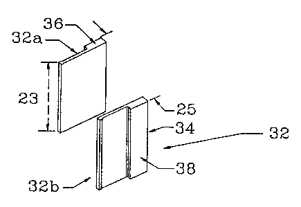
A nine tooth segment 20 is shown in Fig. 1. Segment 20 has a return path
22 having a radial depth 21, an axial length 23, and a circumferential width
25
as more clearly shown in Fig. 2. Circumferentially spaced teeth 24 are formed
on the inner radial end or inside circumferential surface of return path 22.
The
teeth point radially inwardly and the teeth define circumferentially spaced
slots
26. Segment 20 possesses two axially extending radial side surfaces 28 (only
one
of which is completely shown in the perspective). The overall radial depth 27
of
the segment, which is about 0.8 inches (20.3 mm), is a sum of the radial depth
21 of the return path 22 and the radial depth of a tooth. The radial depth 21
of
the return path is about 0.35 inches (8.9 mm) and the radial depth of a tooth
is
about 0.45 inches (11.4 mm). The axial length 23 of a press molded segment is
about 0.947 inches (24 mm). The tips 30 of teeth 24 are circumferentially
wider
than the remaining body 31 of the teeth. The wider tip results in lower flux
densities in that part of the tooth. In designing a stator with half of the
above
number of teeth, it is even more desirable to make the tooth tip 30 wider than
the
tooth body 31 itself, resulting in semi-closed slots 26, as shown and
described.
By arranging twelve of segments 20 in a circular configuration, each
axially extending radial side surface 28 lies on a radial line extending from
the
center of the circular configuration, and the tips of the teeth are all
pointed
radially inwardly. In this manner a complete stator is formed the outer
diameter
WO 94/06192 PCT/US93/08200~
-10-
of which is approximately 8.29 inches (210 mm). Axially extending radial side
surfaces 28 of the return path 22 of each segment may be pressed molded or
machined to have tongue and groove mating surfaces 33 as shown in Fig. 7 or
half lap mating surfaces 35 as shown in Fig. 8.
Although it has been determined that the nine tooth segment is optimal,
other configurations are possible. The largest numYier of segments in a stator
is
equal to twice the total number of teeth in an arrangement where each segment
is a half tooth. Two half tooth segments combined to form a single tooth
segment 32 shown in Fig. 2 where each segment is a circumferential path of a
single tooth. Segments 32 possess a simple, curvilinear return path 34, two
axial
ends 36 (only one of which is shown in Fig. 2) and two axially extending
radial
side surfaces 38 (only one of which is shown in Fig. 2). The dimensions, such
as the axial length 23 of half tooth segments 32 and the overall radial depth
27
of a half tooth segment may be the same as the dimensions for segment 20. Two
hundred and sixteen of the half tooth segments 32 can be arranged
circumferentially (creating spaced slots between the teeth) to form a complete
annular stator. The dimensions of such a stator can be the same as the
dimensions of the stator produced with segments 20. Due to limited die life
and the cost of a high tonnage press, a stator which contains a large number
of
segments is not desirable for economic reasons. As the number of segments
increases, dimensional tolerance can also become a critical factor.
Nevertheless,
in certain circumstances a stator which is made of half tooth segments might
be
satisfactory. At the other extreme, a stator having one hundred and eight
teeth
can be composed of two segments each having fifty-four teeth. This is the
maximum number of teeth on a segment. With respect to dimensional tolerance
and dynamic behavior the fifty-four tooth segment is the most desirable. A
large
number of stators can be made during the operational life of each die.
However,
due to its complex geometry, production of the die required to make this
segment
is relatively expensive. In addition, depending on stator diameter,
maintaining
uniform material density throughout each segment might be difficult. With
respect to construction of the segment and ease of winding, a more reasonable
WO 94/06192 ~ ~ ~ ~ ~ ~ PCT/US93/08200
-11-
solution is to produce a segment which has twenty-seven teeth (four segments
per
stator). A twenty-seven tooth segment 40 is shown in Fig. 3. Generally, the
axial length of any one of the press molded segments such as segments 20, 32
or
40 is 0.947 inches (24 mm) or one third the axial length of a tripart segment.
Because iron losses are controlled on the microscopic level, the axial length
of the
segments is not constrained by electromagnetic properties. The axial length of
a segment is limited only by the precision with which the mold can be made,
and
the uniformity of material density with which the part can be made. It appears
as if these factors currently limit the axial length of the half tooth
segments 32 to
approximately 2-2.5 inches (about 50.8 to 63.5 mm). If possible, it is
desirable
to make the length of the segments the same as that of the motor, however it
is
not necessarily feasible to design one piece segments of such a length that
will
produce acceptable performance specifications. In that case, a plurality of
segments each having an axial length of 0.947 inches (24 mm) can be placed
axially end-to-end to increase the axial length of the stator. That is, a
completed
tripart segment can be produced by creating two additional identical segments
each having an axial length of 0.947 inches (24 mm) and laminating the three
segments together mechanically or with an adhesive, to create a tripart
segment
as shown more clearly in Fig. 3, wherein press molded segment 40 is composed
of three identical sections 42, 44, and 46, each section having an axial
length of
0.947 inches. I~lo additional insulating material is required between such
laminated sections. To date, segments having nine teeth produced in a one shot
molding process having a final axial length of 1.5 inches (38.1 mm) were
destroyed by the force necessary to eject the segments from the mold. The
difficulty in ejecting the segment from the mold and the safety of the die
itself
also determines the maximum axial length of the segment. If the correct
combination of die lubricant, temperature and compressive force is found, it
is
likely that segment lengths in excess of 1.5 inches are attainable.
Stators composed of the tripart segments 20, 40 and mono segment 32 of
the invention can be wound by a number of methods. In a preferred method, the
method made simple by the fact that stators of the invention can be produced
in
CA 02143637 2002-09-18
_12-
sections, is partially illustrated in Figs. 4a through 4c and 5. In Fig. 4a
segments of
Fig. 1 are aligned linearly creating a single row of teeth pointing in the
upward
direction. The teeth are then wound to create the wave winding shown in Fig.
6. The
segmented structures of the invention, with teeth, are structures that permit
winding
without using a mandrel. Wave winding is more fully shown and described in
U.S.
Pat. No. 5,004,944. Wave winding is characterized by a short end turn compared
to
the commonly used lap winding. Wave winding leads to a more compact and lower
resistance winding. In certain cases, the wave winding requires less time to
complete
than a lap winding, resulting in savings in production costs. The winding
shown in
Fig. 6 is the winding for a three phase motor. For multiple turns per slot
motors, the
wave winding may not be desirable. In that case, the press molded segments can
be
wound by lap winding. Winding is preferably carried out with thin, insulated
wire,
such as, for example Thirty gauge wire 37. The open structure of the segments
lined up
linearly facilitates wave winding and the use of parallel, insulated thirty
gauge wire
1 S produces a flexible structure permitting formation of three segments into
the required
cylindrical shape. The wound stator results in motors and generators having a
high
continuous power to weight ratio, generally greater than 1.0 horsepower per
pound. In
preparing the segments for the winding process, the inside surfaces of the
slots are
usually lined with thin insulating paper sold under the trademark NOMEX (not
shown) to protect the winding from damage by the stator core composed of the
molded iron segments and to provide additional insulation from ground. If the
number
of teeth in a stator is large or the size of the slots is small, inserting
paper insulators
can be difficult and time consuming. The alternative is to coat the segments
in a
fluidized bed with an H-class coating. This is a high temperature coating,
withstanding temperatures up to about 130°C'.. Such a coating is sold
by Dexter
Electronic Materials T)ivision, located in Industry, California and Olean, New
York.
The product can be purchased by referring to order No. I7I~1 SEG
WO 94/06192 PCT/US93/08200
-13-
conformal coating powder, an epoxy resin coating powder. This results in a
hard
protective insulating surface on the segments where the copper wires are
wound.
The axially extending radial side surfaces 28 at which the segments are joined
to
each other are kept clean of coating material to allow for the required
physical
contact between them.
As can be seen, with respect to winding simplicity it is advantageous to
have a relatively small number of teeth per segment as shown in Fig. 4b to
avoid
large curvatures in each segment. However, since each individual segment
requires some handling, a large number of segments could increase the total
manufacturing cost for the finished stator winding. On the other hand,
reducing
the number of segments (by increasing segment size) also introduces larger
amounts of curvature as shown in Fig. 4c when the segments are linearly
aligned
on a flat surface. The larger amount of curvature can increase the winding
difficulty. The segment approach provides for a wide variety of designs and
options. Forming the segments into a cylindrical stator is done after the
winding
is completed.
Formation of a stator with winding can also be accomplished by using a
partial jig as shown in Fig. 5. In Fig. 5 eleven stator segments 20 are
arranged,
as shown, on a jig 50. Jig 50 has an axial length equal to or slightly larger
than
the axial length of the stator. The end sections 52 of jig 50 have bores 54
for
receiving threaded fasteners 56 that engage threaded stops members 58. As
illustrated by phantom lines 60, bores 54 are sufficiently large to allow
adjustment
of stop members 58. By this arrangement segments 20 can be circumferentially
arranged on the inside circumferential surface of the jig in a tight fitting
manner
by adjusting the stops 58 and screwing down fasteners 56.
In the assembly shown in Fig. 5, winding the stator is facilitated because
the stator segments are circumferentially positioned and the wire bundles can
be
brought up through the unclosed ends of jig 50. After the assembled eleven
segments are wound, stop members 58 are removed from the jig and the last
section is positioned to complete the circular stator. Winding is then
completed.
This arrangement will reduce the probability of a wire becoming pinched
between
WO 94/06192 PCT/US93/08200
r'
-14-
segments, as may happen when forming the circular stator after winding in
accordance with the method described relative to Figs. 4a through 4c and Fig.
6.
Thereafter, the winding structure can be varnished.
After the winding process is completed, the resulting structure is formed
into a cylindrical shape and accurately sized using cylindrical clamps or a
metallic
ring 62 or rings composed of aluminum or steel, as shown in Fig. 9; the
winding
has been omitted for clarity. Such a ring 62 or housing has an inner diameter
smaller than the outer diameter of a circumferentially assembled stator at
ambient
temperatures. Differential thermal expansion techniques, corresponding to
heating
of clamps or ring 62 and/or cooling of the segments, can be employed during
assembly of the structure to produce, after return to ambient temperature, an
assembly interference fit between ring 62 and the stator formed of the
circumferentially arranged segments. For example, the.segments may be cooled
to reduce their diameter to smaller than the inner diameter of ring 62. The
ring
is then fitted around the circumferential stator. When the segments warm to
ambient temperature an interference fit results. The coefficient of thermal
expansion of the molded segments is approximately 8.0 X 10⁶/°F and the
coefficient of thermal expansion of ring 62, if made of aluminum, is 13.3 X 10-
6/°F and if made of steel is 6.0 X 10'x/°F.
As previously alluded to above, when using the H-class coating material
it is undesirable to coat all surfaces of the segments. This requires masking
of
those surfaces to keep them free of the coating material. It is economical to
reduce labor required in masking the segments to a minimum. One method of
achieving this objective is to assemble, in an interference fit, the segments
comprising the core as described above, in a thin wall tube 90 which acts as a
containment ring for the segments, as shown in Fig. 10. The containment ring
90, made of steel or aluminum, should be the same axial length as the core,
and
the wall should be approximately .050" to .070" thick. The interference fit of
the
containment ring and segments will directly prevent deposition of the H-class
coating on return path 22 and indirectly prevent deposition of the H-class
coating
on axial extending radial side surfaces 28, as each side surface is forced to
abut
WO 94/06192 ~ ~ ~ ~ "~ PCT/US93/08200
-15-
an adjacent side surface. A teflon or nylon cylinder which has an outer
diameter
equal to the inner diameter of the core is then inserted in the inner
diametral
cavity of the core structure to prevent deposition of the H-class coating on
tooth
tips 24. The H-class coating is then applied to this assembly, and the
cylindrical
masking fixture is then removed from the inner diameter of the core. The
coated
structure is placed in an oven at 300° to 450°F for 1-2 hours to
cure the coating.
Excess coating is removed from the outer diameter of the containment ring
using
a turning process on a lathe.
The winding 92 is then applied to the resulting coated
core/containment ring structure, preferably using wave winding techniques.
Winding is accomplished similar to the partial jig method described above,
except
the core structure defines a complete annular structure. The wound core
structure
is then varnished and assembled in an interference fit with finned ring or
housing
62 which is similar to ring 62 shown in Fig. 9 as described above.
The ring 62 or rings used for sizing the stator assembly will become a
permanent part of the stator assembly, comprising what could be considered the
housing. The primary purpose of this housing is to maintain physical contact
between adjacent segments under all operating conditions, in order to prevent
excessive deformation of the stator. The housing is made of steel or aluminum
as discussed above, and may have multiple, radially outward oriented cooling
fins
64 on its outer surface as shown, in Figs. 9 and 10 to enhance the heat
dissipation
characteristics of the motor. The complete structure can then be either
encapsulated in epoxy by vacuum or pressure casting methods or varnished with
a suitable solution in a process similar to that normally used in the
manufacturing
process of conventional electric motors. As in any manufacturing process of
electrical motors, the winding is subjected to testing methods for possible
damage
to the wire insulation. These methods are commonly known as surge and hi-pot
tests.
Shown and described to this point have been segments wherein the teeth
are positioned on the radial inner concave portion of a segment. Fig. 11 shows
two press molded segments 80 arranged circumferentially. These segments each
WO 94/06192 PCT/US93/08200
-16-
have nine teeth, wherein the teeth 82 are formed on the radial outer convex
portion of the segment and point in the outwardly extending direction. Such a
stator is inherently easier to wind than the stators described above because
the
teeth point in the radially outward direction.
Segments 80 have a return path 84, the axial length 85 of which is greater
than the axial length of a tooth body. The teeth 82 of such segments are
substantially centered on the outside convex face of return path 84 which
construction defines shoulders 88. It is not currently possible to form this
segment without using a machining process. In this case, the segment is
pressed
with the teeth being the same axial length as the segment. Then the end
sections
of each segment are ground to form the shoulders. To assemble a complete
annular stator core, the concave inside surfaces of the return paths of twelve
segments 80 are positioned around the periphery of a cylinder (not shown) so
that
the axial side surfaces of a segment contact a corresponding surface of
adjacent
segments and so that the teeth extend in the radial outward direction. The
cylinder is made of aluminum or other non-magnetic metal which is a good heat
conductor and has a length substantially equal to or greater than the axial
length
of the return path of the segments. The cylinder acts as a heat sink for heat
generated by the segments and windings. In order to ensure that the segments
remain in place during winding and when used in an electro-mechanical
transducer having a high power to weight ratio annular rings 86, which in
cross
section are rectangular, are positioned, in an interference fit, around the
shoulders
88 of segments 80 circumferentially arranged on the cylinder. Annular rings 86
are made of a non-magnetic material such as stainless steel or aluminum. After
fitting the annular rings around the shoulders the annular structure may be
wound,
with thin insulated wire, to complete the stator.
In a transducer, the stator, with its aluminum cylinder and annular rings
86, would be stationary and a rotor, mounted for rotation, for instance, on
the
ends of the cylinder rotates about the stator. The heat produced from the
working
transducer can be removed by circulating a cooling fluid through the cylinder.
WO 94/06192 ~ . r~ PCT/US93/08200
-17-
The cooling fluid would enter and exit the cylinder from fittings
communicating
with the inside of the cylinder positioned on the structure used to mount the
rotor.
While preferred embodiments have been disclosed and described, it will
be recognized by those with skill in the art that variations and modifications
are
within the true spirit and scope of the invention. For instance, a stator may
be
formed of six segments having nine teeth each and one segment having fifty-
four
teeth. Any combination of segments is possible. It is noted that the invention
is
also not limited to stator having one hundred and eight teeth. The appended
claims are intended to cover all such variations and modifications.
~..~-~ ', i~r~l;~~-~3'~'~.;l~v~~