Note : Les descriptions sont présentées dans la langue officielle dans laquelle elles ont été soumises.
WO 94/15762 PCT/US93i12663
1
ERGONOMIC UTILITY KNIFEfBOX CUTTER AND METHOD OF MAKING
BACKGROUND OF THE INVENTION
gield of the Invention
The present invention relates to utility knives, and
methods of making such knives. More particularly, the
present invention relates to utility knives which are
particularly adapted for use in cutting open corrugated
cardboard shipping boxes, and include also a cutting guide
serving to guard the exposed end of the cutting blade in
such use. Still more particularly, the present invention
relates to such utility knives which include a somewhat
bulbular or ergonomically-shaped handle or body, a cutting
blade movable in the body to extend a cutting portion of
the blade outwardly of the body at one end of the latter,
externally accessible means for moving the cutting blade
between the extended cutting position and a retracted
position of withdrawal into the handle, and provision for
storage~of several spare blades within the handle.
Related Technoloav
The field of utility knives includes many examples of
previous attempts extending over many years all directed
to providing a utility knife which satisfies one or more
of the many concerns for such knives. Among the concerns
addressed are making a utility knife Which is inexpensive,
safe in a variety of uses, rugged, reduces or prevents
damage to the contents of cardboard boxes opened with the
knife, is durable, easy to use, is easily grasped and
provides good purchase on the knife for security and
certainty in its use even while the user's hands may be
moist and slippery, reduces the fatigue inherent in some
of the strenuous uses of hard cutting for which such
knives are used, provides conveniences in the use and
maintenance of the knife, is attractive, and provides for
WO 94/15762 PGTIUS93I1?6f'
2
the storage of spare knife blades within the utility knife
itself.
For example, United States Patent No. 3,l92,624,
issued in l965 to D. Gringer, is believed to teach a
utility knife in which a handle provides a forward
longitudinal cavity in which is slidably received a blade
carrier member, and a rear cavity in which are received a
number of spare blades. The blade carrier member carries
a double-ended cutting blade, and is movable
longitudinally of the forward cavity between a retracted
safety position with the blade entirely within the handle,
and an extended cutting position in which a triangular end
part of the blade extends forwardly out of the handle.
The handle is vertically split and includes two portions
which are almost mirror images of one another. A screw
secures the two handle portions together and allows their
separation with the use of a screwdriver for substituting
one of the spare blades for a used cutting blade. A
similar utility knife is presented in United States Patent
No. 3,879,847, issued in l975 to D, Roll in which blades
may be changed without disassembly of the handle by
forward extension therefrom of a forward part of a
channel-like blade carrier member. As Roll points out,
his utility knife no longer requires the inconvenience of
carrying a screwdriver with which to open the handle of
prior utility knives. However, his knife also appears not
to offer the convenience of spare blade storage in the
knife handle.
An alternative type of utility knife is represented
by the 1931 Geriaan Patent No. 531,248, and descendants of
the disclosed design. This design of utility knife
includes a flattened tubular handle, with a blade carrier
slidable in the handle between a retracted position
sheathing the blade entirely in the handle, and an
extended cutting position in which part of the blade is
exposed forwardly of the handle. A spring-arm part of the
'~ WO 94I15762 ~ ~ ~ 3 ~ 7 3 PCTIUS93112663
3
blade carrier includes a lug receivable in detent notches
of the handle to retain the carrier in selected positions,
including the retracted position and various positions of
blade extension. A button member is secured to the spring
arm for disengaging the lug from the detent notches and
moving the blade carrier to a selected position. Some
members of this design family include differing handle
designs, differing means of securing the blade carrier in
position, and use differing types of blades. For example,
to the common single-edge razor blade is a favored blade for
many of these utility knives although it has many
deficiencies in such use. That is, the razor blade is
brittle, thin, and not very rugged. Consequently, a razor
blade may break off if, for example, a twisting or bending
moment is imposed on the blade in use. Certain other of
these knives use a trapezoidal-shaped double ended
all-purpose (AP) blade, which is considerably more rugged
than a razor blade.
United States Patents Nos. 2,840,903 3,195,23l;
3,525,l52: 3,621,570: and 4,570,342, may be considered as
representative design descendants of the l931 German
patent discussed above. Generally, this type of knife is
made with a handle of folded sheet metal, having a rather
small edge radius opposite to the blade edge and against
which cutting pressure may be exerted by the user. All of
these knives are relatively thin, and provide only a small
handle edge surface area against which manual cutting
pressure may be exerted. This small handle edge radius
and small edge surface area can combine to make many of
these knives uncomfortable to use, especially in hard
cutting use. Even when the user is wearing gloves, some
of these knives are so thin that an uncomfortable pressure
groove is soon formed in the user's hand after a period of
hard cutting. Users then find themselves shifting the
knife in their hand to avoid the sensitive pressure
groove, and in the process attempting to use the knife in
WO 94I15762 ~~ ~ ~~ ~ ~ ~ ~~, PC'T/US93I126~z
4
a less than optimum grasp. Understandably, this type of
use contributes to fatigue and injuries. While some of
these knives provide a handle with somewhat increased
manual surface area, a11 are deficient to some degree With
respect to the grasp or purchase on the knife afforded to
a user. Especially in hard use, the thin, fragile, or
difficult to control knives of the above category are not
well accepted by users.
A further branch of design in the utility knife area
is represented by those utility knives adapted more
especially for their use in opening cardboard cartons or
boxes. In this use, the carton is generally held in front
of the user With one hand and arm, and is cut by drawing
the knife with the other hand toward the user across the
side wall of the carton. Because such use frequently
involves the need for speedy work, and the cardboard does
present considerable resistance to cutting, flesh wounds
are common when the knife blade springs free at the end of
a cut and catches the user's arm. In this use particular
-20 attention must be given to protecting both a user of the
knife, and the contents of a cardboard carton to be opened
with the knife, from being inadvertently cut. For this
use, United States Patent No. 3,178,812, issued in 1962 to
A.J. Lurie, depicts a utility knife having a pair of
- 25 spaced apart plate-like blade guards, one for within and
the other for outside of a carton. The inner guard is to
protect the carton contents during cutting of the carton
sidewall, and is carried at the end of a hook-like
extension of the handle. This type of utility knife would
30 seem to present inconveniences in use because of the
necessity to provide for entry into the carton of the
inner plate-like guard. A similar hook-like guard is seen
in United States Patent No. 4,167,810, issued in 1979 to
R. Gilbert. The Gilbert teaching includes a formed wire
35 hook-like inner guard for protecting the contents of a
carton frto~ the blade while the carton is opened. A hard
i .,
WO 94I15762 ~ ~. ~ ~ ~ ~ J PCT/US93112663
point is provided for punching a hole in the carton for
subsequent insertion of the formed wire hook.
An alternative form of blade guard, this one for
protecting the knife user, is seen in United States Patent
5 No. 4,675,996, issued in 1987 to T. DuBuque. The Dubuque
knife includes a pair of spring-loaded pivotal guard
plates secured to the handle of the knife in such a way
that they are asserted to prevent accidental exposure of
the blade edge. The guards are stated to pivot and expose
the blade edge when the knife is drawn along the side of
a carton . The guards are said to roll on the cardboard
surface. Why these pivotal guard plates would not also
pivot away to expose the blade if the knife were
inadvertently drawn across the user's arm, for example, is
not clear from the patent.
An alternative form of blade guard for protecting
both user and carton contents is depicted in United States
Patent No. 4,744,l46, issued in l988 to G.G. Schmidt, and
owned by the assignee of the present application. In the
Schmidt knife a planar plate-like guard member lies
adjacent to, but spaced from, the blade in its extended
carton-opening position. The plate-like guard member
provides a guide surface by which the knife may be guided
along the top corner of a carton to be opened while the
carton side wall is cut to remove the carton top. Because
the edge of the blade is recessed behind the edges of the
guard plate, a user of the knife is not likely to be cut
with the knife. Also, because the blade penetrates the
side wall of the carton a controlled amount immediately
adjacent to the top inside wall of the carton, the
contents are not likely to be injured by the blade. The
Schmidt knife also offers a considerably improved ease of
use because its handle is formed of a sturdy aluminum
extrusion offering a considerably larger surface area
against which cutting pressure can be applied by a user of
the knife, as well as more comfortable rounded outer edge
surfaces of larger radius than some other knives. This knife
also includes features avoiding accidental dropping of the
worn blade when replacing the blade is necessary, and provides
for storage of several spare blades within the knife.
A similar guard member is seen in United States
Patent No. 5,054,198, issued in 1991 to R. Gmoch, differing so
far as the guard feature is concerned only in the angular
relation of the guard to the length of the cutting blade.
SUMMARY OF THE INVENTION
In view of the above, the present invention provides
a utility knife comprising: an ergonomically-shaped handle
portion defining a longitudinal cavity at a forward end, a top
surface and an aft recess substantially adjacent said top
surface, a channel member including a pair of U-shaped
confronting channel portions received in said cavity and
secured to said handle portion, a blade carrier member
received in the U-shaped confronting channel portions of said
channel member for receiving a cutting blade defining a
cutting edge, the blade being received such that said cutting
edge faces substantially away from said top surface, a lock to
retain said blade carrier in a selected position relative said
handle portion, and a spare blade holder member pivotally
received into said aft recess.
The channel member preferably defines a pair of
longitudinal grooves and a pair of longitudinal edge surfaces,
the handle portion having plural longitudinal ribs
respectively engaging said grooves and edge surfaces to
support the channel member in opposition to cutting forces.
The utility knife/carton cutter includes a bulbular
- 6 -
62196-627
6
ergonomic handle port ion having an ex ~ ~ ~ur ~c~ which
provides considerable area for application of manual cutting
force to the knife, and which is stippled or textured in
selected surface portions thereof to provide a user of the
knife with a slip-resistant grasp thereon. The handle portion
defines a forwardly-extending elongate longitudinal cavity
separated by a perforate partition
- 6a -
62196-627
WO 94115762 PCTIUS93112663
7
wall from a rearward upwardly-opening recess. In the rear
recess, a spare blade holder member is pivotally received
and movable between a closed blade-retaining position, and
an open blade-releasing position in which a forward
portion of the spare blade holder member is pivoted
upwardly out of the recess and free of the remainder of
the handle portion. In the forward elongate longitudinal
cavity, a channel member is received. The channel member
includes a tab extending through a perforation of the
partition wall into the rearward recess, there to be
permanently retained against the opposite side of the
partition wall to capture the channel member in the
forward cavity. The channel member defines a pair of
longitudinal grooves and a pair of longitudinal edge
surfaces, each of which are engaged by a respective
longitudinal rib within the forward cavity to support the
channel member in opposition to cutting forces on the
knife. Within the channel member, a blade carrier member
is slidably received. The blade carrier member is itself
channel shaped to receive therein an a11 purpose (AP)
blade. Further, the blade carrier is somewhat tray-shaped
to prevent accidental dropping of an old blade when the
blade carrier is moved outwardly of the channel member to
a blade changing position. This tray shape of the blade
carrier also eases insertion of the replacement blade into
the carrier. The blade carrier includes an integral
spring arm portion distally carrying a button member
outwardly extending through congruent longitudinal slots
of the channel member and handle portion. An enlarged
inner collar portion of the button member is receivable
into semicircular enlargements of the channel member slot
to lock the blade carrier member in selected positions of
its mov~nent. An outer end portion of this button member
is accessible to the user on the side of the knife for
unlocking the blade holder and moving the blade to
selected storage or use positions. The channel member
WO 94/15762 PC'TIUS9311?"~
21~~~'~3
8
also defines an integral plate-like guide and blade guard
outwardly of the handle portion. This plate-like blade
guard shields the blade in its carton-opening position and
is angulated toward intersection with the blade to further
reduce the possibility of accidental user contact with the
blade. Also, the angulation of the guide/guard plate
improves separation of the blade from contents of a carton
in that position of the blade. The blade guide/guard does
not intersect with the blade, however. Thus, when the
blade is extended farther outwardly past the guide/guard
plate, an end part of the blade is available for a variety
of utility uses.
As may be appreciated from the above, the present
invention provides a utility knife which offers
unprecedented comfort and convenience in use. The
ergonomic design of the handle portion provides a good
grasp on the knife with plenty of surface area so that
cutting forces do not cause discomfort from concentrated
forces on a small area of the user's hand. The blade
guide/guard provides both improved protection to the user
and improved protection to the contents of a carton when
the knife is put to such carton opening use. Spare blades
are conveniently stored in the rear recess of the knife
handle and are easily accessed without the need for a tool
or any disassembly of the knife. When a blade change is
needed, the tray-like design of the blade carrier presents
the old blade for easy removal and disposal with little
chance of a dropped blade. Also, insertion of the new
blade into the knife is additionally eased because the
user need only lay the new blade into the tray-like
carrier, with engagement of the blade on a pair of
location tangs, and withdraw the blade carrier into the
handle to a use or storage position. Because the handle
portion of the knife may be made of polymer material
having a considerably lower coefficient of heat transfer
than conventional knives with metal handles, the present
WO 94I15762 ~ ~4 PCTnJS93l11.663
9
knife is much warmer and more comfortable to use in cold
environments, such as refrigerated food storage
warehouses.
These and other advantages of the present invention
will be apparent from a reading of the following detailed
description of a single preferred embodiment of the
invention, taken in conjunction with the following drawing
f figures .
BRIEF DESCRIPTION OF THE DRAWING FIGURES
Figure 1 provides a side elevation view of a utility
knife/box cutter according to the present invention:
Figure 2 is a side elevation view of the utility
knife/box cutter seen in Figure 1, with a spare blade
storage member pivoted upwardly out of a handle portion of
the knife to a blade releasing position, and the cutting
blade of the knife advanced out of the handle to one of
two use positions therefor;
Figure 3 provides an exploded perspective view of the
utility knife/box cutter with the spare blade holder
member and other component parts of the knife shown in
positions to better illustrate their structure and
cooperation in the knife;
Figure 4 is an enlarged fragmentary cross section
view generally at line 4-4 of Figure 3, and with the spare
blade holder member pivoted into its blade retaining
position within the handle portion;
Figure 5 provides an enlarged fragmentary cross
sectional view similar to Figure 4, but showing the
utility knife from the opposite direction of view at the
same 4-4 section line:
Figure 6 is a cross sectional view taken at line 6-6
of Figure 2, also shown enlarged to better depict details
of the structure; and
Figure 7 is a fragmentary view showing the utility
knife/box cutter of the present invention in use to cut
WO 94115762 PCTJUS93I12~~3
21~3~73 to
open a corrugated box, and depicting additional salient
features of the invention.
DESCRIPTION OF THE PREFERRED EMBODIMENT
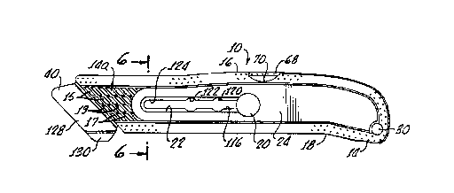
Viewing Figure 1, a utility knife/box cutter to is
shown in side elevation view. The depicted knife 10 is
right-handed, a left-handed knife being the same in all
respects while being a mirror image of the right-handed
knife. The utility knife l0 includes a somewhat bulbular,
elongate, and ergonomically-shaped handle portion,
generally referenced with the numeral 12. Handle portion
12 includes a peripheral portion 14 which is textured or~
stippled to provide a good grip for a user of the knife
10. A side surface portion 14a of the handle portion 12
is also textured to provide secure engagement of the
user's right thumb, recalling that the depicted knife 10
is right-handed. The surface portion 14a defines a
plurality of shallow recesses 15, each shaped like a
parallelogram, and cooperating to define plural
longitudinal ribs 17 and angulated ribs 19. The ribs 17
and 19 are each disposed to provide purchase of a user's
thumb on the surface 14a to resist the predominant cutting
forces in the use of the knife 10. That is, the ribs 17
and 19 are diposed generally perpendicularly to the
primary (arrow 17a) and secondary (arrow 19a) cutting
forces exerted by a user's thumb on the knife 10 during
use thereof.
Further, the handle portion 12 includes both an upper
outwardly convex curved handle surface portion 16, and a
longitudinally spaced lower outwardly concave curved
handle surface portion 18. The handle portion 12 is also
somewhat thick and rounded (viewing Figure 6) so that the
curved surface portions 16,18 cooperate to provide a
handle laying naturally in the palm of a user's hand, with
convex surface 16 against the palm, and the fingers
WO 94/15762 ~ ~ !~ ~ ~ ~ 3 PCT/US93I12663
11
wrapped generally leftwardly of the concave curved surface
18.
Figure 1 depicts the utility knife in a safe storage
condition with a cutting blade (not seen in Figure 1)
withdrawn into the handle portion 12. As will be seen, an
operating button 2o extends outwardly through a slot 22 on
a side surface 24 of the handle 12 , and is used to move
the cutting blade from the storage position to one of two
use positions, or to a blade changing position.
Turning now to Figure 2, the utility knife 10 is
shown With a spare blade storage member 26 pivoted
upwardly at its forward end 28 out of the handle portion
12. The spare blade storage member 26 is pivoted in the
handle portion 12 by a pivot pin 30. Within the spare
blade storage member 26, a trapezoidal pocket 32 receives
a plurality of trapezoidal all-purpose utility blades 34.
As will be seen, the pocket 32 communicates with a
slightly smaller window 36 (best seen in Figure 3) opening
away from the viewer of Figure 2 so that spare blades
cannot escape in that direction, but so that a finger may
be used to bring the blades forward for removal and use of
the nearest blade. At this point, it is well to note that
the handle portion 12 and spare blade holder member 26 are
both formed of a strong, shape-retaining, but somewhat
yieldable, injection molded engineering thermoplastic.
For example, the portion 12 and member 26 may be formed of
a fibre reinforced polymer (FRP). A specific example of
the type of material which may preferably be used to form
the handle 12 and member 26 is a glass fibre reinforced
Nylon 6 material, although there are other materials in
the market such as ABS and Delrin which will also serve
well in the present use.
Figure 2 also shows the button member 20 advanced
forwardly from the storage safe position of Figure 1 to a
first use position shown in dashed lines, and in which a
forward portion 38 of a cutting blade advances outwardly
WO 94115762 PCTlUS93J12'
~~.~36~3 12
of the handle portion 12 behind a plate-like blade
guide/guard member 40, to the position shown entirely in
dashed lines. Alternatively, the button member 20 may be
advanced to a second use position shown in solid lines on
Figure 2, in which the cutting blade 34 extends beyond the
guide/guard member 40 so that the portion 38 is partially
exposed, as seen in solid lines on Figure 2. Still
alternatively, as will be explained, the button member 20
may be advanced forwardly still further in slot 22 to a
to blade changing position so that one of the spare blades 34
may be substituted for the cutting blade.
Considering now Figures 3-6 in conjunction, and
recalling that structure already described by reference to
Figures 1 and 2, it is seen that the handle portion 12
defines both an elongate forwardly extending cavity 42,
and an upwardly and rearwardly opening rear recess 44. A
partition wall 46 (best seen viewing Figures 4 and 5)
separates the cavity 42 and recess 44, and defines an
aperture 48 communicating therethrough. The recess 44 is
cooperatively defined by a pair of spaced apart side walls
50, extending upwardly from a lower wall 52 (viewing
Figures 3 , 4 , and 5 ) . The lower wall 52 also defines a
rear abutment surface 54 (seen in Figure 4), the
importance of which will be described below. Side walls
50 include arcuate end parts 56 and define a pair of
aligned bores 58 (viewing Figure 3). The spare blade
holder member 26 at an arcuate end part 60 includes a bore
62 cooperable with the bores 58 to receive the headed
pivot pin 30. After its receipt into the bores 58,62, the
far end of pin 30 is swaged to permanently retain both the
pin 30 in these bores, and the spare blade holder member
26 in the recess 44. The arcuate end parts 56 and 60 are
disposed toward the lower side of the handle portion 12.
That is, the end parts 56 and 60 are diposed toward the
lower concave surface portion 18 and away from the upper
convex surface portion 16 so as to assist in forming a
WO 94/l5762 ~ ~ 3 ~ ~ ~.~I PGTlUS93/I1663
13
somewhat angulated shape for the handle portion 12 in side
view, recalling Figures 1 and 2. Thus, the combination of
the rounded cross sectional shape, upper convex surface
portion 16, lower concave surface portion 18, and the
relative lowered position of the arcuate end parts 56,60
all cooperate and contribute to providing an overall
ergonomic shape for the knife 10.
Viewing the spare blade holder member 26 in greater
detail, it is seen to include an upper wall part 64~which
completes the outer convex surface 16 when the spare blade
holder member is pivoted inwardly of the recess 44, and a
lower wall part 66 . Both of the wall parts 64 , 66 bound
the pocket 32. The upper wall part 64 includes a forward
portion 68 which is accessible with a finger nail via a
crescent-shaped groove 70 in the nearer of the two side
walls 50, viewing Figure 3, to pivot the spare blade
holder member 26 out of the recess 44. Extending into the
pocket 3 2 , and cooperating to define the window 3 6 , the
spare blade holder member 26 includes a flange-like wall
portion 72 spanning between the wall portions 64,66. At
the front of pocket 32 and also spanning between the wall
portions 64,66, the spare blade holder member 26 includes
a trapezoidal shaped flange-like wall portion 74.
Depending from the upper wall part 66 is a transverse rib
76 receivable into one of the upper notches 80 of the
blades 34.
At its forward end 28, the spare blade holder 26
includes a depending J-shaped wall portion 80, which at
its free end 82 is somewhat flexible. The free end 82 of
wall portion 80 defines a forwardly opening transverse
notch 84. Viewing Figure 4, it is seen that the partition
wall 46 includes a pair of transverse stiffening ribs
86,88 extending between the side walls 50, and
respectively disposed immediately above and below the
aperture 48. When the spare blade holder member 26 is
pivoted into the recess 44, the notch 84 receives the
WO 94I15762 PCTlUS9311'''3
~I~3~'~3 14
upper one (86) of the ribs 86,88 to retain the holder
member 26 in cavity 44. Because the material from which
the handle member 12 and spare blade holder member 26 is
formed is somewhat yieldable, the spare blade holder 26
may be pivoted out of recess 44 with the force of a finger
nail in groove 70 lifting wall portion 68. That is, the
depending wall portion 80 will yield elastically to allow
the spare blade holder member 2 6 to pivot out of recess
44. This outward pivotal movement brings an abutment 54a
of the member 26 into engagement with the abutment 54 of
the lower wall 52 to limit further outward pivotal
movement of the spare blade holder member 26.
Also viewing Figures 3-7 in conjunction, it is seen
that the cavity 42 of handle portion 12 receives an
elongate channel member 90. In fact, the channel member
90 defines a pair of confronting channel portions 92,94
separated by a w_eb portion 96. At its aft ~ end, the
channel member 9o includes a tang 98 extending from the
web portion 96 through the aperture 48 into recess 44, and
there being cut out in a generally C-shape to form a
laterally displaced tab 100. The web portion 96 also
defines a pair of longitudinal grooves 102,l04, while the
channel portions 92, 94 at their free side opposite the web
portion 96, define a pair of side surfaces 106,108.
Within the cavity 42, the handle portion 12 includes
two pairs of longitudinal r~ ibs.110,112. The ribs 110,l12
respectively are received into grooves Z02,104, and engage
side surfaces 106,108, to securely position the channel
member in the cavity 42. Additionally, the channel member
90 includes an upper pair and a lower pair of nubs l14
extending respectively upwardly and downwardly from the
channel member adjacent the forward end thereof. When the
channel member 90 is inserted into the cavity 42 during
manufacture of the knife 10, its outer surfaces are snugly
engaged by the somewhat yieldable material of the handle
member. The ribs l10,112, engage grooves 102,104, and
WO 94/1S762 ~ ~ PCTIUS93112663
side surfaces 106,108, respectively, to further insure
sturdy attachment of the channel member 90 into the handle
portion 12, and to resist cutting forces. And further,
the nubs 114 wedge into the cavity 42 to provide
5 additional securement for the channel member 90. One of
the side walls 50 de=fines a staking aperture 50a (best
seen viewing Figure 4 ) through which a staking tool may
laterally enter recess 44 to laterally displace the tab
l00. Once this staking operation has been performed, the
10 channel member 90 is permanently captured in the cavity
42.
Channel member 90 also defines a longitudinal slot
l16. This slot 116 includes a semi-circular enlargement
118 at the aft end thereof, and a pair of spaced apart
15 semi-circular enlargements 120,122 spaced forwardly of the
aft enlargement 118. Also, slot 116 includes a forwardly
extending slot portion l24 forward of the enlargement 122.
With the channel member 90 in the cavity 42, the slot 22
of handle 12 is congruent with slot l16. Forwardly of the
handle portion 12, the channel member 9o integrally
includes the plate-like blade guide/guard 40. In order to
define the guide/guard 40, the channel member 90 includes
a first inner and laterally angulated portion 126.
Forwardly of the portion 126, the channel member 90 also
includes a second outer and laterally angulated plate-like
portion 128, which is larger than the portion 126, and is
angulated laterally in the opposite direction. At its
lower extent, the second portion 128 includes an outturned
plate portion 130 serving like a ski tip to facilitate
sliding of the guide/guard 40 over the outer surface of a
carton, as will be seen.
Within the channel member 90 is slidably received a
cutting blade carrier member 132, which itself is channel
or tray-shaped. That is, the blade carrier member 132
includes a web portion l34, with an upper l36, and a lower
138, laterally extending wall part. The upper wall part
WO 94/15762 PCTlUS93lIZf'-
~'1436~3 16
136 includes a pair of spaced apart notches l40 in which
respective tangs 142 extend laterally to respectively
engage the forward one of the notches 80 of the cutting
blade 34, and to engage the aft end edge 34a of this
cutting blade (viewing Figure 3). At its forward end, the
wall part l36 also includes an inturned tab 144 engageable
with the forward end edge 34b of the cutting blade 34.
Integrally formed as part of the web l34, the carrier
member 132 includes a spring arm portion 146 which near
IO its distal end I48 defines an aperture 15o.
As is seen in Figure 3, the button 20 is defined as
the outer end portion of a button member referenced with
numeral l52. The button member l52 includes a shaft l54
with an enlarged chamfered collar portion l56, and a rivet
end section 158 extending therefrom. During manufacture
of the knife 10, with the blade carrier member l32 in the
channel member 90, the button member 152 is receivable
inwardly through the slots 22 and 116 of the handle
portion 12 and channel member 90, respectively, to dispose
the enlarged collar portion 156 in the slot enlargement
118, and to extend the rivet section 158 through the
aperture 150. An opening l60 (best seen viewing Figure 3)
in the handle portion 12 aligns with the slot enlargement
118, and with rivet section 158, so that a riveting tool
may be laterally inserted to head section 158.
Thereafter, the blade carrier member l32 is permanently
captured in channel member 90. The enlarged collar
portion 156 is sized for a snug laterally but not
longitudinally movable fit in the enlargements 118,120,
and 122. Thus, when the collar portion 156 is received in
one of these slot enlargements and is retained therein by
the bias applied by the integral spring arm portion 148,
the blade carrier member Z32 is not moveable along channel
member 90. However, lateral pressure on button 20 is
effective to depress the collar portion l56 out of the
slot enlargements l18-1Z2, and to allow the blade carrier
WO 9d115762 ~ I ~ 3 6 '~ 3 ~T~~3~12663
17
member to be moved along the channel member 90 by use of
button 20 with the shaft portion 154 being moveable
longitudinally of slot 116.
When the button member 20 is moved to the forward end
of slot 116, the blade carrier member l32 is advanced to
a blade changing position partially outwardly of the
channel member 90. In this position of the carrier member
132 , a blade receiving recess 162 cooperatively defined by
the web l34, walls 136,138, tab 144, and the collar
portion l56 of button member 20 is accessible to remove a
warn blade 34, and to replace this blade with a fresh one.
A user of the knife 10 need only to turn the knife to with
the side seen in Figure 1 upwardly, and slide the button
fully forward in its slot. The old blade is presented
15 to be picked out of recess 162, and will not fall
therefrom. Subsequently, the user need only lay the =rash
blade into the recess l62, engaging the forward one of
the tangs l42 with the forward one of the notches 80 of
the fresh cutting blade, and then sliding the button 20
20 rearwardly to one of the positions defined by enlargements
l18-122.
Figure 7 depicts the knife 10 in use as a box cutter
with a cutting blade 34 extended to the carton-opening
position (i.e., button member 2o at enlargement 120).
This figure illustrates that the outer plate-like portion
l28 of the blade guide/guard 40 is preferably angulated at
an angle of about 14 degrees with respect to the length of
the knife 10, and that the tip of the cutting blade is
recessed a preferred distance l64 behind the forward edge
of the plate-like portion l28. This preferred angulation
is believed to provide the best combination of protection
for carton contents, as depicted in Figure 7, and
protection for a user of the knife against accidental cuts
when the blade recess distance l64 is about 3/l6th inch.
While the present invention has been depicted,
described, and is defined by reference to one particularly
WO 94/15762 pCT/US93112~"'
~143~'~3 18
preferred embodiment of the invention, such reference does
not imply a limitation on the invention, and no such
limitation is to be inferred. The invention is intended
to be limited only by the spirit and scope of the appended
claims, which also provide a definition of the invention.
What is claimed is: