Note : Les descriptions sont présentées dans la langue officielle dans laquelle elles ont été soumises.
CA 02143794 2004-05-18
GK-ISL-713
1
KEY AND INSTALhATION DOUBhE CYLINDER FOR A SECURITY LOCK
BACKGROUND OF THE INVENTION
a) Field of the Invention
The invention is directed to a key and an installation
double cylinder for a security lock with two cylinder halves
which are connected with one another, a cylinder core and
tumblers which are constructed as core pins and housing pins
and can be brought into line by means of the key which can be
inserted into the keyway to release the cylinder core for
rotation.
b) Description of the Related Art
A key and installation double cylinder of this kind is
known from CH-A-626 679 by the present applicant. The two
cylinder halves are connected and reinforced by a crosspiece
of chromium-nickel steel. The cylinder housing of the two
cylinder halves is formed by successive disks which are
connected with one another in a stationary manner. This
installation double cylinder already offers high security
against break-in.
OBJECT AND SUMMARY OF THE INVENTION
The primary object of the present invention is to
increase security against break-in.
Therefore, in accordance with the present invention,
there is provided a key and installation double cylinder for ~~
security lock comprising a key having a bit, a first cylinder
half for positioning at an inner side of an access portal, a
second cylinder half for positioning at an outer side of said
access portal, a cylinder core and tumblers which are
constructed as core pins and housing pins and can be brought
into line by means of said key, said tumblers being located in
said first cylinder half only, said second cylinder half being
free of core pins and housing pins, said cylinder core
including a rotor disposed in said second cylinder, said rotor
being solid except for a keyway, said key for being inserted
into the keyway to release the cylinder core for rotation,
said key having, at its bit, a lengthening element by which
CA 02143794 2004-05-18
GK-ISL-713
la
the tumblers in an oppositely located cylinder half can be
brought into line for free turning upon an insertion of said
key from an outer side of the double cylinder, said key having
a standard element which is disposed in said rotor upon
insertion of said key from the outer side of the double
cylinder, said lengthening element being connected by a swivel
to said standard element.
The object of the invention is met in a key and
installation double cylinder of the type mentioned above in
that the key has, at its bit, a lengthening element by which
the tumblers in an oppositely located cylinder half can be
brought into line for free turning. In the installation double
cylinder according to the invention, locking operation is also
ensured when one cylinder half has no tumblers. In this
cylinder half without tumblers, the rotor or a rotor half can
be produced, e.g., from hardened steel. When
'.
installing the double cylinder, this cylinder half is generally
arranged on the outside. The cylinder half with the tumblers is
accordingly located on the inside of the door. The hardened-
steel rotor arranged on the outside of the door protects the
tumblers arranged on the inside and would have to be removed in
order to break in, e.g., it would have to be cut out along its
entire length which would be extremely involved. Since the key
extends substantially along the entire length of the double
cylinder, there is no need for a coupling so that manufacture is
simplified. Since the outer sleeve can be produced without
tumblers and since no coupling is required, as was just
mentioned, the cylinder can be adapted exactly to any door
thickness on the keying side. Accordingly, the cylinder can be
prevented from projecting out on the outside and there is no need
to attach an escutcheon.
According to a further development of the invention,
the rotor is continuous and is provided with a thickened center
part. The thickened center part effectively prevents the rotor
from being broken off and pulled out.
According to a further development of the invention,
the rotor has an insert which is drilled with a determined
drilling pattern. The number of locking permutations can be
doubled in a simple manner by rotating the insert.
When the lengthening element at the key is arranged so
as to be movable and foldable according to a further development
of the invention, the key can be given a conventional key length
and will not be conspicuous in a bunch of keys. The key
preferably comprises a standard element and the lengthening
element. The length of the key can be adapted to cylinders of
any length by the appropriate length of the lengthening element.
It is essential that the key be designed in such a way
that it locks only from the outside or from both the outside and
inside. Accordingly, locking authority in a security area can be
structured in a more deliberate fashion than was previously
possible. In addition to the key according to the invention, the
3
installation in question can also have conventional keys for
locking from the inside.
Further advantageous features are contained in the
dependent claims, the following description and the drawing.
An embodiment example of the invention is explained
more fully in the following with reference to the drawings.
BRIEF DESCRIPTION OF THE DRAWINGS
In the drawings:
Fig. 1 is a view of a key, according to the invention,
and an installation double cylinder, according to the invention,
in which the individual parts are spread out for illustrative
purposes;
Fig. 2 shows a variant of an installation double
cylinder, according to the invention, in which the individual
parts are again spread out;
Fig. 3 shows another variant of an installation double
cylinder according to the invention;
Fig. 4 shows a key according to the invention in
partial section;
Fig. 5 shows another plan view of the key according to
Fig. 4; and
Fig. 6 shows a schematic view of the control bore holes
of a key according to the invention.
DESCRIPTION OF THE PREFERRED EMBODIMENTS
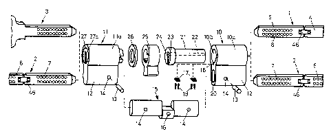
Figure 1 shows a cylinder half 10 with a housing l0a
which has a cylindrical recess lOb for receiving a rotor 21. The
rotor 21 is produced from hard material, in particular hardened
steel, and is outfitted with hard-metal pins 22. A key guide 24
extends along the entire length of the rotor 21. The rotor 21 is
inserted into the opening lOb from the rear side of cylinder half
10 and contacts the housing l0a at the rear by a flange 23.
Slides 17 which hold the rotor 21 in the pull out position by the
214~~~
4
action of spring elements 19 when the key is pulled out are
inserted in a longitudinal groove 18 of the recess lOb. The
cylinder half 10 preferably has no tumblers and, in conformity
with the rotor 21, no radial bore holes. In a break-in attempt,
the rotor 21 which is produced from resistant material could only
be cut out with a great deal of effort. Since the flange 23
contacts the housing l0a at the inside, it is also impossible to
pull the rotor 21 out of the housing l0a from the keying side.
The cylinder half 10 is connected with a second
cylinder half 11 by a crosspiece 15. The two ends of the
crosspiece 15 engage, respectively, in a recess 20 of a cylinder
pocket 12. The crosspiece 15 is connected with the cylinder
halves 10 and 11 in a stationary manner by transverse pins 13
which are inserted into bore holes 14. A threaded bore hole 16
for a locking screw which fixes the double cylinder in the door
lock is provided in a central thickened portion of the crosspiece
15.
The second cylinder half 11 likewise has a cylinder
housing lla in which a rotor 27 is supported. This rotor 27 is
secured at the back by a ring 26. Cylinder half il can be
constructed in a manner known per se, i.e., it can have
conventional tumblers which can be brought into line by a
conventional key 3 for releasing the rotor 27. After inserting
the key 3 into the key guide 27a, the rotor 27 can accordingly be
rotated along with the driver 25. On the other hand, if the key
3 is inserted into the key guide 24 of cylinder half 10, only the
rotor 21 can be turned and, in so doing, does not carry along the
driver 25. Accordingly, the key 3 cannot turn the driver 25 and,
consequently, a locking bolt of the lock cannot be actuated. The
double lock cylinder is generally inserted into a door in such a
way that cylinder half 10 is arranged on the outside and cylinder
half 11 is arranged on the inside. The double lock cylinder can
then only be actuated with the key 3 from the inside.
2143~~~
However, it is possible to actuate the rotary lock
cylinder from the outside with keys 1 and 2 shown in Figure 1.
Each of these keys 1 and 2 has a lengthening element 5 and 7,
respectively, which is provided with bore holes 8, known per se,
S and is arranged at the front end of a standard element 4 and 6,
respectively. When the key 1 is inserted into the lock cylinder
from the outside, the lengthening element 5 lies in the key guide
27a of rotor 27 and brings the tumblers of cylinder half 11 in
line by means of the control faces of bore holes 8. The rotors
21 and 27 and, along with them, the driver 25 can then be turned.
However, the rotary lock cylinder cannot be operated by key 1
from the inside, since the standard element 4 which then lies in
rotor 27 has no corresponding bore holes 8.
However, it is possible to operate the rotary lock
cylinder from the outside and from the inside with key 2 which
has corresponding bore holes 8 at the lengthening element 7 and
standard element 2 as is shown in Figure 1. A lock installation
can accordingly have keys 1, 2 and 3 shown in Figure 1. As was
already explained, these three keys have different locking
possibilities. In this way, locking authority in the security
area can be organized more expediently. Of course, a lock
installation generally has a plurality of double lock cylinders
and many keys.
The double lock cylinder shown in Figure 2 has a rotor
30 which is produced from a continuous cylindrical piece of
hardened steel. The rotor 30 has a thickened portion 31
approximately in the center, a driver 53 being slid onto this
thickened portion 31. The driver 53 engages in a groove 54 of
the rotor 30 by a shoulder 53a and is accordingly connected with
rotor 30 so as to be fixed with respect to rotation relative
thereto. Each end 55 and 56 of the rotor has a recess 36 and 37,
respectively, for an insert 33, 32 and is supported in
corresponding recesses 58 and 57 of the cylinder housing lla and
214394
6
10a. A key guide 44 extends along the entire length of the rotor
30.
The inserts 33 and 32 are drilled according to a
determined drilling pattern and receive core pins 35. The
cylinder housings lla and l0a have conventional housing pins, not
shown, which cooperate with the core pins 35 in a known manner.
Insert 32 is preferably shorter than insert 33 and,
correspondingly, recess 37 is shorter than recess 36. The end 55
of the rotor 30 is accordingly substantially sturdier than the
end 56 and offers great resistance to tampering, e.g., with a
cutter. Apart from high security, a substantial advantage of the
lock cylinder according to Figure 2 consists in that the locking
possibilities can be doubled by rotating the inserts 32 and 33.
A substantial increase in the number of locking permutations is
accordingly made possible in a very simple manner without
additional production costs.
The housings l0a and lla can be lengthened by means of
lengthening elements 28 and 29. A key 1 and 2 associated with
the latter can be adapted in a simple manner to the respective
length of-the double cylinder by producing the lengthening
element 5 and 7 with a corresponding length. The standard
element 4 and 6 need not be adapted.
In the construction according to Figure 3, a rotor 38
is provided which has a recess 41 at its end 40 for an insert 42
only on the inside. The rotor 38 likewise has a keyway 44
extending along its entire length. The other end 39 of the rotor
38 has no bore holes for tumblers and is solid with the exception
of the keyway 44. In this case also, a driver 43 is slid onto
the rotor 38 so as to be fixed with respect to rotation relative
to it. As in rotor 30, this rotor also has a thickened center
part 31 which effectively prevents the rotor from being pulled
out of the cylinder housing. In other respects, the lock
cylinder shown in Figure 3 is constructed in the manner described
above.
~~4379~
Figures 4 to 6 show a key 2 with standard element 6 and
lengthening element 7. As will be seen from Fig. 5, the key can
be shortened by swiveling the lengthening element 7 around an
articulation 46, i.e., it can be shortened to the conventional
length for a key of this type. Reference number 7a shows the
lengthening element in the working position and reference number
7b shows the lengthening element in the folded in position.
Folding can be effected in the directions indicated by the double
arrows 52 and 60.
The articulation has a connection plate 47 which is
swivelably connected with the standard element 6 and with the
lengthening element 7 by means of transverse pins 48. Pins 49
which are displaceable in a defined manner are supported in
stepped bore holes 51 of standard element 45 and lengthening
element 7 and contact a planar end side 47a of the plate 47 under
the influence of a pressure spring 50 in each instance. The
lengthening element 7 is fixed in position 7a by pins 49, but can
be swiveled out of this position by a comparatively small lateral
force. In position 7b, the pins 49 contact end sides 47b (Figure
6) and also fix the lengthening element 7 in this folded in
position. The key 2 can accordingly be brought to a conventional
key length in a simple manner. This is also true of the key 1
shown in Figure 1. Constructions in which the lengthening
element 7 cannot be swiveled are also possible. Finally,
constructions in which the bit of the key 2 can be reduced in a
telescoping manner are also possible.
Figure 6 shows a possible arrangement of bore holes on
the bit of the key 2.
While the foregoing description and drawings represent
the preferred embodiments of the present invention, it will be
obvious to those skilled in the art that various changes and
modifications may be made therein without departing from the true
spirit and scope of the present invention.