Note : Les descriptions sont présentées dans la langue officielle dans laquelle elles ont été soumises.
2I4543~
BACKGROUND OF THE INVENTION
Field of the Invention
This invention relates to a low temperature starting
system for internal combustion engines running on middle
distillate fuels and other low volatility alternative-fuels,
including single and multi-cylinder.compression ignition,
spark ignition, and surface ignition engine~configurations.
The invention is applicable to internal combustion
engines operating on a wide variety of liquid and gaseous
fuels in vehicle applications, stationary applications, and
portable applications such as generator sets. The invention
allows for extremely low temperature starting of an engine
with minimal expenditure of cranking energy, minimal
cranking duration and speed, and minimal time between
initiating the starting system and sustained engine
operation.
Internal combustion engines operate by combustion
processes which take place in the cylinders (combustion
chambers of the engine). In spark ignition engines a
combustible air/fuel mixture is drawn into the combustion
chamber where a spark or ignition source is used to ignite
the mixture causing expansion of the combustion gases,
thereby producing power at the crankshaft. The air/fuel
mixture must be inducted at a temperature sufficient to
promote partial vaporization of the fuel. If the temperature
of the mixture is too low, vaporization of the fuel will not
be sufficient to produce a combustible mixture at the
ignition source during the compression stroke, and the
engine will not start.
The minimum ambient temperature at which unaided
starting can occur depends on the type of fuel used. Low
volatility fuels such as JP5,JP8, and diesel fuels will not
allow spark ignition engine starting even at room
temperature without low temperature starting aids.
- 1 -
G:\~IHIdN\PATENTS\9U319.DOC
214~43~
In compression ignition engines air is drawn into the
combustion chamber where it is compressed. Compression
causes the temperature of the air ~o increase. When the fuel
is injected into the combustion chamber, it mixes with the
hot air and spontaneously combusts if a sufficient quantity
of air-fuel mixture in the combustion chamber is above the
auto-ignition temperature of the fuel. Auto-ignition causes
the combustion gases to expand and power is produced at the
crankshaft. The auto-ignition temperature of conventional
compression ignition fuels is typically quite high, for
example diesel fuel has an auto-ignition temperature range
between 700 - 900~F. The maximum combustion chamber
temperature prior to sustained combustion is dependent on
the compression ratio of the engine.. If the mixture
temperature in the combustion chamber does not reach the
auto-ignition temperature, the injected (atomized) fuel will
not ignite and the engine will not start. Auto-ignition is
discussed in detail in Internal Combustion Engines and Air
Pollution by Edward F. Obert (Intext Educational
Publishers).
At low ambient temperatures, the air-fuel mixture in
the combustion chamber does not reach the auto-ignition
temperature upon compression due to the low temperature of
the inducted air and the high rate of heat loss to the
engine components during compression. If the rate of heat
build-up in the combustion chamber does not exceed the rate
of heat transfer out of the combustion chamber, the engine
will not start.
Description of the Prior Art
Ancillary fuels, such as ether, have been used as an
aid in starting internal combustion engines at low ambient
temperatures. United States patent number 4938180 employs a
controlled ether injection system to allow low temperature
starting. The high volatility and rapid preparation rate of
ether during the compression stroke creates a combustible
- 2 -
G:\1IN10R0\PA1EA75\90319.DOC
214~43~
mixture at low temperatures which aids in starting spark
ignition engines. The low auto-ignition temperature of the
air/ether mixture aids in starting compression ignition
engines.
However, there are many drawbacks to using ether as a
starting aid. Its low auto=ignition temperature causes
premature combustion and undesirably~high rates of . ..
combustion pressure rise (knock) in compression ignition
engines, and may also cause overspeeding of the engine upon
startup since compression ignition engines usually do not
have any means of controlling the rate at which the
air/ether mixture is inducted.
The high volatility, anesthetic properties, and low
auto-ignition temperature of ether also present a safety
hazard with regard to storage and use. In addition, ether
tends to dry the cylinder walls of the engine resulting in
excessive engine wear.
Numerous other methods have been employed to improve
low temperature starting capabilities. Many of these have
involved preheating major engine components such as the
engine block, cylinder head, etc. These methods require very
large expenditures of energy due to the large mass of metal
that is heated. Some compression ignition engines have
electrically powered glowplugs in pre-combustion chambers,
which permits the retention of a bulk temperature sufficient
to ignite the injected fuel at low ambient temperatures.
Glowplugs are not normally used in open chamber compression
ignition engines since the area of the exhaust valves must
be reduced below the optimal size to allow space for the
glowplug. Substantial electrical power is required to
operate a glowplug and the minimum ambient temperature at
which the engine will start depends on the engine design.~A
further drawback is that as the temperature decreases the
cranking time increases. Engine cranking, especially at low
temperatures causes excessive engine wear since the engine
- 3 -
C:\.IHiOPD\PA7EHf5\90319.OOC
_ 2~4543~
components do not receive optimal lubrication at such low
cranking speeds. Fuel ends up on the cylinder walls diluting
resident lubricating oil, which dilutes the oil in the
crankcase.
Other starting methods involve preheating the inducted
air or air/fuel mixture to improve starting. United States
patent number 4682576 assigned to Mazda Motor Corporation,
Hiroshima, Japan employs electric heating elements placed in
the induction system of a compression ignition engine to
heat the air in conjunction with a valve system which causes
high intake velocities during cranking to create compressed
air in the cylinder through inertia. Electric heating
elements in the inducted air stream typically require
substantial energy input for a moderate increase in air
temperature at cranking speeds.
In some instances, a flame source has been installed
into the induction system whereby some inducted air is
heated and some inducted air is used to support flame
combustion. This method is limited in that increasing the
inducted air temperature requires increasing the combustion
heat supplied by the flame and in so doing the oxygen
content of the air is depleted, impeding the tendency for
combustion of the fuel in the combustion chamber.
An object of the invention is to allow compression
ignition engines and low volatility fueled spark ignition
engines to start at extremely low ambient temperatures with
minimal cranking time (reduced engine wear) and minimal
energy expenditure without using ancillary fuels. It is
assumed that at low temperatures the fuels would have
appropriate pour and cloud points.
Another object is to reduce exhaust emissions and white
smoke during the start-up and warm-up periods at low ambient
temperatures by improving the combustion processes during
the start-up and warm-up period.
- 4 -
C:\.IN10ND\PA2EHT5\90314.DCC
CA 02145435 2005-05-18
SUMMARY OF THE INVENTION
Accordingly the present invention provides a cold
starting system for a fuel-injected, compression ignition or
spark assisted internal combustion engine operating on middle
distillate fuels and other low volatility alternative fuels,
comprising a means for switching between a start-up mode in
which a fuel-injection system for said internal combustion
engine is inactive and a normal mode in which the fuel-
injection system is active, an air intake duct for supplying
intake air to the engine during normal operating conditions, a
throttle means for restricting air flow to said engine through
said air intake duct during start-up so as to prevent the
engine from taking in excess cooled or partially heated air, a
means for mixing fuel with said intake air in the intake duct
in said start-up mode so that an air-fuel mixture is supplied
to the engine and an auxiliary heating means operating
independently of said engine for pre-heating said air-fuel
mixture in said start-up mode at a flow rate limited by said
throttle means to a temperature sufficient to ensure
sustainable combustion without undue ignition delay during a
normal engine cycle prior to attainment of normal engine
operating conditions whereby said engine can be started on
said pre-heated air-fuel mixture supplied through said intake
duct and then switched to fuel injection when normal operating
conditions have been attained.
The expression "undue delay" means undue ignition delay
that leads to excessive rates of combustion pressure rise,
which must be avoided.
In a preferred embodiment of the invention a metered
quantity of fuel is added to the intake air prior to pre-
heating, and the engine is started in a fuel-metered mode.
- 5 -
CA 02145435 2005-05-18
After ignition and an appropriate warm-up period, the engine
is switched over to the diesel fuel injection mode.
The invention involves two main components, namely the
induction system heat exchanger and the heating source for
the heat exchanger, which are added to the internal
combustion engine to allow low temperature starting. The
heat exchanger in conjunction with an airflow restriction
device is used to allow highly efficient heating of the
inducted air or air/fuel mixture during cranking of the
engine, such that auto-ignition temperatures are reached in
compression ignition engines and combustible air/fuel
mixtures are generated in spark ignition engines, thereby
allowing the engines to start more rapidly with less
20
- 5a -
~14543~
cranking energy, less cranking speed and at extremely low
temperatures.
The heat exchanger is heated by a heating source which
may be a fuel fired burner (wick or wickless), an electrical
heating device, a chemical heating device, thermal storage
device, or other means.
Tests~~have shown that the invention will allow engine
starting (hand starting of small internal combustion
engines, battery starting of large engines) down to
extremely low ambient temperatures (-50.0°C ) within a few
revolutions of the crankshaft at low cranking speeds. During
warm-up the heating source is left on to continue heating
the intake air or air-fuel mixture such that combustion is
improved and emissions and white smoke are reduced. The
heating source is turned off by a manual or thermoelectric
switch as the engine approaches operating temperature. At
very low temperatures white smoke may re-occur when the
heating source is shut off; in this case auxiliary heat is
supplied to the intake air or air-fuel mixture through a
heat exchanger which is heated by the engine exhaust
manifold.
The heat exchanger is used to efficiently transfer heat
from a heating source to the inducted air or air/fuel
mixture during engine cranking. The efficiency of the heat
exchanger is improved by limiting the mass flow of air or
air-fuel mixture through it with the throttle means. In the
case of a carburetted spark-ignition or surface-ignition
engine, the carburetor choke valve may be placed in the
closed or semi-closed position to limit the airflow into the
engine and thus limit the mass flow of air through the heat
exchanger.
In the case of a compression ignition (diesel) engine,
the mass flow of air through the heat exchanger may be
limited by placing a restrictive device such as an orifice
or valve in the induction airstream and/or by restricting
- 6 -
C: \~INKiPU\ PATEMS\90a 19.DOC
2145435
the air flow path inside the heat exchanger. Restricting the
airflow increases the residence time of the air or air/fuel
mixture in the heat exchanger so as to heat the air or
air/fuel mixture to a higher temperature.
The heat exchanger may be placed in-line with the main
induction system. If a carburetor or air/fuel mixing device
is used in~the induction system the heat exchanger is placed
between the carburetor or fuel metering device and the
combustion chamber of the engine. If an air/fuel mixing
device is not present in the induction system, the heat
exchanger is placed in the intake air induction system
between the air filter and the combustion chamber.
The heat exchanger may also be placed off to the side
of the main induction system as an auxiliary system whereby
all of the air or air/fuel mixture entering the engine
during starting is diverted through the heat exchanger by
means of a diverter mechanism in the main induction system.
After the engine has started the diverter mechanism is
positioned such that the air or air/fuel mixture is allowed
2fl to flow into the engine through the main induction system
thereby allowing normal engine operation.
The induction air heat exchanger may be heated by a
variety of heating sources. The type of heating source
depends on the application. Fuel fired burners ( wick and
wickless types), electrical energy, chemical energy,
thermal storage devices or other means may be used to
provide heat to the induction air heat exchanger. Fuel fired
burners require minimal electrical energy supply (small
batteries e.g. two D - cells) to cause initial ignition of
the fuel. Combustion of fuel in the burner is used to
provide the necessary heat.
The invention also provides a method of cold starting
an internal combustion engine operating on middle distillate
fuels and other low volatility alternative fuels, comprising
the steps of supplying a restricted flow of intake air to
C:\.INfORD\PA7ENT5\90319.DOC
2145435
the engine; and heating the intake air during cold starting
to a temperature sufficient to ensure sustainable combustion
without undue ignition delay during an engine cycle prior to
attainment of normal engine operating conditions.
There are thus four basic configurations of the
invention depending on the type of internal combustion
'engine to which it is applied.
In an auxiliary heat~exchanger system, where only
intake air is heated, the heat exchanger is placed off to
the side of the main induction system as an auxiliary system
such that all of the inducted air (only air) during starting
and warm-up passes through the heat exchanger. As the engine
warms up a thermoelectric or manual device opens a diverter
valve which allows the inducted air to pass through the main
induction system. In this way the heat exchanger can be made
small since the air passes unrestricted through the main
induction system when the engine is warmed up.
In an auxiliary heat exchanger system, where an air-
fuel mixture is heated, the heat exchanger in conjunction
with an auxiliary carburetor or other air/fuel mixing device
is placed off to the side of the main induction system as an
auxiliary system, such that all of the inducted air/fuel
mixture during starting and warm-up passes through the heat
exchanger. As the engine warms up a thermoelectric or manual
device opens a diverter valve which allows the engine to
operate on inducted air or air/fuel mixture passing through
the main induction system. In this way the heat exchanger
can be made small since the air or air-fuel mixture passes
unrestricted through the main induction system when the
engine is warmed up.
In a main induction system heat exchanger, where only
intake air is heated, the heat exchanger is positioned in
the main induction system such that all the intake air is
heated. During normal engine operation at load all of the
inducted air must pass through the heat exchanger regardless
- g _
C:\.IN10R0\PAS~NTS\90319.DOC
214~43~
of whether heat is being applied to the heat exchanger or
not. As a result, the heat exchanger must be quite large
such that it does not unduly impede the airflow and thereby
reduce engine power. This heat exchanger configuration will
require a higher pre-heat temperature than the auxiliary
heat exchanger system.
In a main inductiomsystem heat exchanger, where an
air-fuel mixture is heated, the heat exchanger is positioned
in the main induction system between the combustion chamber
and the carburetor or other air/fuel mixing device and heats
the air/fuel mixture as it is inducted into the engine.
During normal engine operation at load all of the inducted
air-fuel mixture must pass through the heat exchanger
regardless of whether heat is being applied to the heat
exchanger or not. As a result the heat exchanger must be
quite large such that it does not unduly impede the airflow
and thereby reduce engine power. This heat exchanger
configuration will also require a higher pre-heat
temperature than the auxiliary heat exchanger system.
As previously noted the heat exchanger requires a means
of restricting the inducted air or air/fuel mixture passing
through it during starting and warm-up. The restriction
device limits the mass flow of air or air-fuel mixture
through the heat exchanger such that heat is more
effectively transferred to the air or air/fuel mixture.
Limiting the quantity of air or air/fuel mixture
inducted through the heat exchanger reduces the chance that
low temperature ambient air or air/fuel mixture may enter
the combustion chamber without being preheated. It was
determined that when a small quantity of very high
temperature air or air fuel mixture was inducted into the
combustion chamber of an engine, starting/cranking times
were reduced and starting occurred at lower ambient
temperatures than when a greater amount of moderately high
temperature air was inducted into the combustion chamber.
- 9 -
C:\~IH10PD\PA1EHT5\90319.DOC
~~4543~
The restriction device also effectively enrichens the
combustion mixture whether applied to a spark ignition or
compression ignition engine by reducing the amount of
airflow to the combustion chamber without reducing the fuel
flow. Enrichening the air/fuel mixture or decreasing the
induction airflow without decreasing the amount of fuel
metered per engine revolution statistically increases the
probability that a~sufficient number of fuel molecules will
~be properly prepared in the combustion chamber in time to
support and sustain combustion.
BRIEF DESCRIPTION OF THE DRAWINGS
The invention will now be described in more detail, by
way of example only, with reference to the accompanying
drawings, in which:-
Figure 1 is a horizontal sectional view of the engine
and heat exchanger components;
Figure 2 is a vertical sectional view of the heating
source ( diesel fuel fired wick type burner );
Figure 3 is a side view of the bottom portion of the
heater;
Figure 4 is a horizontal sectional view of the engine
and heat exchanger components in a second embodiment of the
invention;
Figure 5 a vertical sectional view the engine and heat
exchanger of the second embodiment;
Figure 6 a side view of the bottom portion of the
heater;
Figure 7 is a plan view of a third embodiment of a heat
exchanger; and
Figure 8 is an vertical sectional view of the heat
exchanger shown in Figure 7; and
Figure 9 is a graph showing pressure against crankshaft
angle for a compression ignition engine.
- 10 -
C:\.IN10RD\PA'1~NTS\90314.DOC
DESCRIPTION OF THE PREFERRED EMBODIMENTS
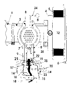
Referring now to Figures 1 to 3, the cold-starting
system comprises cylinder head (intake valve area) 1, main
induction system 2, diverter valve 3, air filter casing 4,
air filter element 5, air filter casing cover 6, heat
exchanger 7, heat source shroud 8, insulation 9, and
diffuser screen 10. Air supply cap ll~fits onto heat
exchanger 7 and is connected through air supply tube 12 to
air filter casing 4.
The heater comprises perforated combustion plates 13,
wind baffle plates 14, fuel level control float 15, needle
valve and seat 16, fuel inlet tube 17, fuel tank 18, and
fuel wick 19, wick advance-retraction lever 20, flame
extinguishing flaps 21, spring-loaded ignition device 22,
ignition power leads 23, diverter valve lever 24, wick guide
25, and heat source (fuel fired burner) 26.
This configuration of the low temperature starting
system was used to allow hand starting of a compression
ignition, single cylinder, naturally aspirated, four-stroke
direct injection diesel engine (2 kW generator set)
operating on arctic diesel fuel and synthetic lubricants at
-50.0 ~C. The lowest ambient temperature at which the engine
could be manually started without using a starting aid was -
e
5.0 C.
Upon initiating the low temperature starting system,
°' diverter valve 3 is positioned (as shown by the solid
outline ) by the diverter valve lever 24 such that no air
may flow through the main induction system 2 without first
passing through the heat exchanger 7. Next the heat
exchanger 7 heating source 26 is turned on by first raising
the arctic diesel fuel soaked wick 19 through the wick guide
25 via adjusting the wick advance-retraction lever 20.
The ignition device 22 is then engaged such that
electric energy from two D cell batteries (not shown) passes
through the ignition power leads 23 to the ignition device
- 11 -
C:\YIN10RD\PA7~H75\90319.DOC
22. Electrical energy is converted into heat by the ignition
device 22 which ignites the arctic diesel fuel soaked wick
19. In an emergency situation, such as battery failure, the
fuel soaked wick 19 can be ignited by a match, lighter or
other heat source. Blue flame combustion of the arctic
diesel fuel occurs between the perforated combustion plates
13, causing'the hot.combustion products ~o rise and pass
between the heat exchanger 7 and the insulated 9 heat source
shroud 8. This results in external heating of the finned
heat exchanger.
The insulation 9 of the heat source shroud 8 may be on
the outside of the heat source shroud 8 as shown in Fig. 2
or on the inside of the heat source shroud 8. A fuel tank
18, fuel level control float 15, and needle valve and seat
16 are used to control the fuel level in the heating source
26 such that the wick 19 is properly saturated with fuel.
Wind baffle plates 14 are used to prevent wind currents from
affecting the combustion flame.
Upon cranking to start the engine, ambient air is
ducted through the air filter casing 4, into the air filter
element 5, then through the air supply tube 12 and air
supply cap 11. The air then passes through a diffuser screen
10 which restricts the flow such that the heat exchanger 7
can effectively raise the air temperature to a value near
the temperature of the heat exchanger 7 without allowing any
low temperature or partially heated air to enter the engine
combustion chamber.
The heated air enters the main induction system 2 and
then proceeds into the cylinder head 1 where it is
compressed inside the engine and thus further heated such
that auto-ignition temperatures are reached and sustained
combustion can occur. Combustion causes expansion of the
gases in the engine thereby producing the necessary power to
start the engine.
- 12 -
G:\~IH16RD\PA2ENSS\90I19.DOC
_ 214~~3~
After startup the engine is allowed to warm up for a
few minutes at which time the diverter valve 3 is opened
manually or by a thermoelectric switch position indicated
by the dotted outline such that the air entering the engine
is not restricted, thereby allowing the engine to produce
maximum output power. Next the heat source 26 is shut off by
adjusting the wick advance-retraction lever 20 to retract
the wick l9~and by deploying the spring loaded flame
extinguishing flaps 21 to extinguish the flame.
Testing at -50.0 °C ambient temperatures with arctic
diesel fuel required 4 minutes of preheating applied to the
heat exchanger 7 by the heat source 2f at which time the
generator set engine was hand started with one pull on the
recoil starting mechanism. The engine was allowed to warm up
before shutting off the heating source 26 and only a minimal
amount of white smoke was observed during start up. The
diverter valve 3 was opened after warm-up to allow air to be
inducted through the main induction system 2 to allow
unrestricted airflow into the engine for operation under
load. Exhaust heat from a heat exchanger on the exterior of
the exhaust manifold (not shown) was then used to heat the
inducted air to allow efficient engine operation with
minimal exhaust emissions and without white smoke.
It should be noted that configuration no. 3 (Main
Induction System Heat Exchanger, Heating of Air Only)
provided similar test results to those outlined above in
configuration no. 1. The engine started at -50.0 °C on
arctic diesel fuel with approximately 4 minutes of heat
exchanger preheating.
Referring now to Figures 4 to 6, like parts have like
reference numerals. This configuration of the low
temperature starting system, which includes a carburetor 33,
was designed to allow a spark ignition engine to start and
operate on JPS, JP8 and similar middle distillate fuels. The
test engine was a small generator set engine originally
- 13 -
G:\~INIdtD\P7~1EM5\9C~319.DOG
214~43~
designed to operate on gasoline that could not be started on
either JP5 or JP8 fuels at room temperature without the
application of a starting aid. The low temperature starting
system as described by configuration no. 4 allowed the
engine to be started on both fuels at -38.0 °C. Lower
ambient starting temperatures are probable but have not been
attempted- to date. , ~ ~ '
Upon initiating the low temperature starting system,
the carburetor choke valve is closed to restrict the airflow
into the heat exchanger. Next the heat source 26 of heat '
exchanger 7 is turned on by first raising the fuel-soaked
wick 19 through the wick guide 25 by adjusting the wick
advance-retraction lever 20. The ignition device 22 is then
engaged such that electric energy from two D cell batteries
(not shown) passes through the ignition power leads 23 to
the ignition device 22. Electrical energy is converted into
heat by the ignition device 22 which ignites the fuel soaked
wick 19.
I'n an emergency situation, such as battery failure, the
fuel soaked wick 19 can be ignited by a match, lighter or
other heat source. Blue flame combustion of the fuel occurs
between the perforated combustion plates 13, causing the hot
combustion products to rise and pass between the heat
exchanger 2 and the insulated 6 heat source shroud 5.
This results in external heating of the finned heat
exchanger. A fuel tank 12, fuel level control float 9, and
needle valve and seat 10 are used to control the fuel level
in the heating source 19 such that the wick 13 is properly
saturated with fuel. Wind baffle plates 8 are used to
30~ prevent wind currents from affecting the combustion flame.
Upon cranking to start the engine, ambient air passes
through the air filter casing assembly 4_then through the
carburetor 3 (carburetor choke valve placed in the closed
position). As the air passes through the carburetor 3, fuel
- 14 -
c:w~nonweA,~rsv9oma.ooc '
_ ~14~4~~
is drawn into the airstream by the vacuum generated in the
carburetor 3 from the choking effect.
The air/fuel mixture then enters the heat exchanger 2
at low pressure due to the carburetor 3 choke used to
restrict the air flow. The mixture is heated by the heat
exchanger 2 such that the fuel vaporizes forming~an easily
ignited combustible mixture which enters the combustion
chamber through the cylinder head intake port 1. The
w combustible air/fuel mixture is then ignited by~the spark
ignition device spark plug in the combustion chamber causing
the combustion gases to expand and produce the necessary
power to start the engine.
After startup, the engine is allowed to warm up for a
few minutes at which time the carburetor 3 choke valve is
opened such that the air entering the engine is not
restricted, thereby allowing the engine to produce maximum
output power. Next the heat source 19 is shut off by
adjusting the wick advance-retraction lever 14 to retract
the wick 13 and by deploying the spring loaded flame
extinguishing flaps 15 to extinguish the flame.
Testing at -38.0°C ambient temperatures required 4
minutes of preheating applied to the heat exchanger 2 by the
heat source 19, at which time the generator set engine was
hand started with one pull on the recoil starting mechanism
using JP5 and JP8 fuels.
It was determined that the starting and operating
characteristics of engines which require the heat exchanger
to heat an air/fuel mixture could be improved by modifying
the inside of,the heat exchanger to incorporate V-shaped or
square shaped circumferential internal grooves. At -38.0°C
the test engine started and operated significantly better
with the addition of the internal grooves to the inside of
the heat exchanger.
The engine was allowed to warm up before shutting off
the heating source 19 and only a minimal amount of white
- 15 -
C:\. IN.OPD\PA7ENt5\90719.ooC
2I4~43~
smoke was observed during start up. The carburetor 3 choke
valve was opened after warm-up to allow air to be inducted
without restricting the airflow into the engine for
operation under load. Due to operational instability
difficulties and excessive white smoke, exhaust heat from a
heat exchanger on the exterior of the exhaust manifold (not
shown) was then used to heat the inducted air to~allow
v ' efficient~engine operation with minimal exhaust emissions
. and without white~smoke.
It should be noted that Configuration no. 2 (Auxiliary
Induction System Heat Exchanger, Heating of Air/Fuel
Mixture) provided similar test results to those outlined
above in Configuration #4. The engine started at -38.0°C on
JP5 and JP8 fuels with approximately 4 minutes of heat
exchanger preheating.
Referring now to Figures 7 and 8, the heat exchanger
comprises a brass tube 100, approximately 2.5 cms. square in
cross section and 8.5 cms. long. A set of vertical flue
tubes 101, which are finned on the outside, pass through the
tube 100 without communicating with the interior thereof so
as to carry hot air through the tube 100. Intake air flows
through throttle 102 in end piece 103 and through connecting
pipe 104 to the tube i00. From there, after being heated, it
passes through connecting pipe 105 to intake manifold 106.
The volume of air within the tube 100 is approximately 25
cc.
The burner is similar to that of the embodiment shown
in Figures 5 and 6. The combustion plates 13 have a
plurality of small holes 107. The small holes permit air to
pass through to the wick 19. The result is a spreading out
of the blue flame combustion 108 from the wick 19, which
tends to fill the whole space between the combustion plates
and increase the quantity of heat generated by the burner.'
Small flame jets appear at the holes 107, with the wick just
providing the vaporized fuel to feed the blue flame
- 16 -
C:\~IHiORp\PATENTS\903::.DOC
_ 214~~~~
combustion between the baffle plates 13. The hot combustion
gases then pass through vertical tubes 101, exchanging heat
with intake air flowing through tube 100. Cover 109 helps to
prevent downdraughts through the heat exchanger vertical
tubes 101.
In this embodiment, atomized fuel from reservoir 18 is
metered~into the throttle 102 through nozzle 110 of fuel
pipe 111.~During the cold starting operation of the diesel
engine, the normal.diesel fuel injection system is ~ w
disengaged, and the engine aspirates a hot mixture of air
and atomized fuel in the manner of a carburetor. After
starting, the engine is switched back to normal operation
using fuel injection.
Figure 9 shows the auto-ignition point A for a
15. compression ignition engine under normal operating
conditions and will be recognized by one skilled in the art.
The object of the arrangement described is to heat the
intake air to a temperature sufficient to achieve auto-
ignition upon cold starting and to ensure sustainable
combustion without undue ignition delay prior to attainment
of normal operating conditions. When fuel is added to the
air in the throttle 102, with the arrangement described, the
air in the heat exchanger 100 should be heated to about
290°F (determined by measuring the temperature of the brass
wall of tube 101). The throttle 102 is 0.25 inches in
diameter, and the size of nozzle 110 is 0.0135 inches (#80
drill size).
With fuel metered into the throttle 102, a homogeneous
hot air charge is metered into the engine. This ensures that
the whole charge ignites at the compression ignition
temperature in contrast to the conditions that prevail when
a fuel charge is injected directly into the combustion
chamber. In the latter case, the fuel ignites first just at
the periphery of the spray.
- 17 -
C:\~INIOH~\PA1~M'S\90719.DOC
- . 214535
Under certain conditions, the fuel pipe 111 can be
dispensed with if the intake air is heated to a much higher
temperature, in the order of 700-800°F. In this case, the
normal diesel fuel injection system is turned on.
Engine knock is another factor that has to be
considered. It has been found that knock can be controlled
~by not letting the~air~temperature get too high, since this
is conducive to premature ignition.
For mechanically blown, super-charged engines, an air
bleed may be provided from the high pressure side of the
blower to the air intake of the system.
The invention thus provides a practical cold starting
system for compression ignition engines. It can also be used
to reduce the cranking requirements at higher temperatures
and thus permit the use of lighter duty cranking motors and
batteries in compression ignition engines.
- 18 -
C:\~IELORD\PATEHTS\90314.DOC