Note : Les descriptions sont présentées dans la langue officielle dans laquelle elles ont été soumises.
WO 94/08322 PCr/US93/09256
, 2145877
METHOD, APPARATUS AND SY:i I tM FOR TRANSMITTING AND RECEIVING
DATA IN A MOVING LINEAR CHAIN
Field of the l"~e..lion
The present invention relates to an information transmission and reception
system, modeled on a linear chain, for use primarily in collision avoidance. In a
linear chain utilizing the invention, a data signal is sent from a first and forward
most unit through the chain to a last unit. The information sent from the first unit
is transmitted rearwardly by each subsequent unit in the chain wherein each unitmay interpret and modify the signal being sent. At any point in the chain, a unit
may analyze the l,ansn,itted signal to obtain information about conditions forward
of that unit. Appropriate actions may then be taken by an operator of any unit.
Background of the l,~ tion
Many devices have been proposed to assist the motorist of a vehicle in
avoiding collisions. One area of the art can be considered proximity detectors
which rely on the amplitude of a received signal to indicate that a certain minimum
distance has been established. These devices require that the lead automobile
and the following automobile possess the same equipment. These devices
generally utilize an auxiliary emitter and receiver to indicate the relative distance
between a lead automobile and a following automobile. Devices of this nature rely
on amplitude of the l,ans"~illed waves to trigger a warning system on a following
automobile. For example, a lead car emits light waves and when a following car
encounters these waves, an alarm is triggered to indicate to the following motorist
that she or he is in close proximity to the lead car. A representative patent in this
field is U.S Patent No. 3,892,483 issued to Saufferer on July 1, 1975. Sauffererdiscloses a distance warning device for vehicles. His invention concerns the
rearward transmission of waves so that a following vehicle would receive the
SU~STITUTE SHEET
CA 0214~877 1999-03-17
waves and either indicate that the following vehicle was too
close, or automatically brake the following vehicle to avoid a
collision. Saufferer relies on wave detection or monitoring of
wave amplitude as the means for determining distance between
the two vehicles.
Another area of the art can be considered distance
measuring devices that rely on the Doppler effect. These
devices are autonomous -- they do not require that another
vehicle have a compatible system. These devices generally
utilize a wave emitting and receiving component located on the
primary vehicle. By emitting wave energy and analyzing the
reflected wave, an approximation as to distance between the
primary vehicle and another object can be determined. When a
certain minimum value corresponding to a minimum safe distance
is reached, the motorist of the primary vehicle is alerted or
his or her vehicle is caused to slow in response thereto. A
representative patent in this field is U.S. Patent No.
4,833,469 issued to David on May 23, 1989. David discloses a
proximity sensing system that uses the Doppler principle to
warn a motorist of a vehicle that he or she is approaching an
object at an unsafe speed. This is accomplished by comparing
the relative speeds of the vehicle to the measured object.
Both of these systems, the proximity detectors and the
distance/velocity devices using the Doppler principle, look
only to the vehicle directly in front of or behind the
motorist. These systems are designed to warn a motorist that
an unsafe condition may exist based upon distance
considerations. These systems are reactive and not proactive
i.e., these systems warn a motorist only after a hazardous
situation has been encountered.
Under many circumstances, knowledge of the condition of a
vehicle directly in front of a motorist is adequate. That, of
course, is the purpose of brake lights and turn signals.
However, as the nations' highways become more and more
congested, more and more ~'chains" are formed. These chains, a
term used from the common phrase "chain reaction", occur when a
linear progression of vehicles closely follow one another. It
is in these situations that accidents are very likely to occur
.
L
., .. . ., , . , ~ ... . . ~
CA 0214~877 1999-03-17 .
2a
- especially when driving conditions are poor such as during a
snow storm or in dense fog. For example, from 1981 to 1989 783
people died on California
X
, ,._ ~ . , ~ ....... ..
W O 94/08322 2 1 ~ 5 8 7 7 PC~r/US93/09256
~, 3
highways because of fog related accidents. Clearly, many of these accidents
could have been avoided if each motorist in the chain of vehicles knew of the
preceding vehicle's actions without relying upon significantly impaired, external
visual cues.
Often, a motorist immediately observing the brake lights of a preceding
vehicle does not realize his or her minimum stopping distance may be greater
than that of the preceding vehicle. Or even more common, a prececling vehicle
can see a h~ardous condition and be prepared to respond; however, those
motorists following this vehicle are shielded from that critical information and must
only rely on the brake lights of the preceding vehicle to inform them of forth
coming adverse conditions. This problem is best exemplified where a tractor and
trailer truck obstructs a motorist's view of conditions in front of the truck. For
example, if the brakes of a vehicle in front of the truck are applied, the motorist
following the truck must wait for the truck to apply its brakes, change lanes, or
otherwise become aware of the condition that requires braking or avoidance.
In chains, the delay from motorist to motorist in responding to brake lights
of the vehicle in front of him or her becomes significant. On the average, it takes
0.25 seconds for the human brain to observe and analyze a condition, and an
additional 0.25 seconds for a corresponding reaction to the observation to occur.
Consequently, each motorist in a chain of vehicles imparts an average of a 0.5
second delay in response to the system. In a five automobile chain, the last
motorist will observe a brake light on the preceding vehicle no sooner than two full
seconds after the situation has ma"i~sled. However, if the last motorist in a chain
was able to determine whether or not any precedi, Ig motorist, other than the
immediately preceding motorist, in the chain was braking, then that motorist could
ANTICIPATE braking, thus he or she could begin decelerating prior to observing atraditional indication that there was a need to brake.
During adverse driving conditions, a reaction delay is even more
undesirable. The above described situations assume that a motorist's perceptionsare not impaired. However, in adverse driving conditions such as bad weather,
smoke, or dust, etc., a motorist's ability to perceive h~ards is significantly
reduced. Further, a motorist's ability to observe the condition of a preceding
Sl~BSTlTUTE SHEET
W O 94/08322 PC~r/US93/09256
2~s~
.. ",_,
vehicle is aiso impaired. In addition, road conditions may cause the effective
braking distance of a vehicle to be significantly grealer than when traveling during
favorable road conditions. The ability to anticipate hazardous conditions by
receiving information not subject to human reaction delays and not subject to
5 visibility limitations would significantly decrease the occurrences of chain reaction
type, multiple vehicle collisions and injuries.
Therefore, there is a need for a distant early warning system for use by
moto, isLs and the like to provide information to such operators about actions and
conditions occurring in front of them. Information such as whether or not
10 preceding vehicles in a chain of vehicles are decelerating would permit a motorist
to prepare to avoid hazardous conditions that could damage property or injure
persons.
SUMMARY OF THE INVENTION
The present invention comprises a method, an apparatus, and a system for
receiving, perceiving, and l,ans",itting electromagnetic signals through a series of
movable, independent units in a substantially linear chain of units. Each unit has
a processing unit coupled to an emitter, a detector, means for detecting
20 deceleration of the unit, and means for detecting deceleration of a preceding unit.
A simple form of the invention is disclosed wherein the means for detecting
deceleration of the unit comprises monitoring an inertial sensor or the unit's
deceleration device. The means for detecting deceleration of a preceding unit
comprises monitoring a range computing device such as a Doppler device or a
25 direct angle measuring device, or by a passive device such as brake light
monitoring device, e.g. a frequency and amplitude sensitive photoelectric detector.
A general form is also disclosed wherein a preceding unit encodes the transmitted
signal to contain information relating to deceleration of that unit and/or any
preceding units from which information relating to deceleration is obtained. To
30 enhance the utility of the apparatus, a display panel is provided for displaying the
information contained in the signal. Finally, a complex form is disclosed wherein
the encoded signal comprises information relating to the number of units in the
SUBSTITUTE SHEET
CA 0214~877 1999-03-17
chain, the number of decelerating units in the chain, the
length of the chain of units, the average velocity of the
units, and mass of the chain, as well as other non-operational
information such as vehicle identification, motorist
information, etc. A more sophisticated display panel is
provided to more adequately display the complex information
contained within the signal.
The principal object of the invention is to provide all
units in a chain of units with information concerning the
actions taken by or conditions of preceding units. In the
simple form, each unit has a single state binary emitter for
transmitting an identifiable signal, and a corresponding
detector. The emitter transmits an identifiable signal upon
(1) detecting a decrease in relative velocity of a preceding
unit, (2) receiving via the detector the identifiable signal,
or (3) detecting a decrease in relative velocity of the unit
itself. In this manner, all subsequent units in the chain are
informed that a preceding unit is decelerating, even if the
unit cannot be seen directly or an immediately preceding unit
is not decelerating. A feature relating to this form of the
invention limits the effective transmission/reception distance
of the apparatus to avoid signal overlap.
In the general form, each unit continuously emits a
variable state encoded signal. As a first unit approaches a
second unit, the detector of the first unit receives the
signal. The processing unit then is set to analyze the
information encoded in that signal. Four distinct states are
provided for: A first transmitted bit indicates that the
second unit has or has not detected the deceleration of any
unit preceding it; a second transmitted bit indicates that the
second unit has or has not begun decelerating. Consequently,
there are three distinct pieces of information: Whether the
first unit is within range of the second unit; whether any
units that may precede the second unit are decelerating; and
whether the second unit is decelerating.
In the complex form, each unit continuously emits a signal
comprising "packets" of information in the manner of binary
transmissions used in digital communications. The use of a
CA 0214~877 1999-03-17
5a
standard protocol permits the mass transfer of large volumes of
data information. As stated above, such packets may include
the number of units in the chain, the number of decelerating
units in the chain, the length of the chain of units, the
average velocity of the units, and mass of the
X
W O 94/08322 21~5~1~ PC~r/US93/09256
6 _~
chain, as well as other non-operational information such as vehicle identification,
motorist information, etc. Such information may find use in personal areas or inpublic areas such as law enforcement.
In a preferred embodiment of the apparatus, a motor vehicle comprises
each independent unit. The emitter is mounted so as to face rearwardly and the
detector is mounted so as to face forwardly. In this embodiment, the signal is
transmitted rearwardly from the vehicle. If a following vehicle is within the range of
the emitter, the following unit may receive the signal, process it, and display and
forward the signal with or without augmentation, depending upon the conditions.
If a following vehicle is equipped with the present apparatus, a system of the
invention is formed.
Therefore, a system of a preferred embodiment comprises two or more
units equipped with the apparatus which are in data communication with each
other. Each unit receives a data encoded signal and may convert the signal to anaudio and /or visual display. In addition, each unit may augment the received
signal to provide following units with an appropriately updated, data encoded
signal.
A method of the invention comprises l,ansri,itting a data encoded signal
rearwardly to the direction of normal travel by a first unit, receiving the dataencoded signal by a second unit, processing the signal into appropriate audio
and/or visual form while augmenting the signal with information pertaining to the
receiving unit if necessary, and ll~nslllillil1g the combined data information in a
direction opposite to the normal direction of travel of the second unit.
Therefore, it is an object of the present invention to provide an apparatus
for use in a system having two or more apparatus wherein the status of a first unit
is l,ans",illed rearwardly so that it may be received by a second, following unit
whereupon the second unit may receive and analyze the data signal and transmit
it with possible augmentation concerning the status of the second unit to a third
unit, and so on.
It is also an object of the present invention to provide a methodj an
apparatus, and a system that eliminates delayed human reaction time when
reacting to preceding decelerating or stationary units. A benefit of this invention is
~SmUTE SHEET
WO 94/08322 PCI~/US93/09256
21~S877
that by providing each unit in a chain o, units with information about units
preceding it, an operator of a unit can be better prepared for adverse conditions.
It is another object of the presen~ invention to provide an information
condui~ commencing from the first unit t~ the last unit in a chain. By providing5 such information, any unit in the chain OT units c~n analyze the i-,ror",alion coniai,)ed in the conduit to determine ,f specific action is required.
It is a further object of the present invention to provide the dror~,nentioned
information to a motorist independant of visibility conditions, thereby significantly
decreasing a motorist's reliance on visual cues exterior to the unit where such
10 cues may be absent or limited.
A feature of the present invention provides for indicaiing to an operator of a
unit that a chain of units has forrr!ed and tnai the operator's unit is part of that
chain; that ~t least one unit in the chain may be decelerating and/or that an
immediately precedirg unit is decelerating.
Another feature of the present invention provides for a first unit to have a
rearwardly facing light so~rce, p~eferabiy a blue light, to indicate to a following
unit, possibly not possessing the present invention, ihat a motorist in a unit
preceding the first unit is braking and that caution should be exerc;sed.
Yet another feature of the present invention provides for the lransr"ission
20 and reception of additional information such as the number of units in the chain,
the numb~r and identity of units in the chain being braked. the length of the chain
of units, the average velocity of the units, and mass of the chain, as well as other
non-op~rational information such as vehicle identification, motorist information,
etc. Reception of this i"tor~"ation when processed by a microprooessor permits
25 an operator to obtain information about current operating conditions that would
otherwise be unavailable to him or her. This information can be further processed
by the microprocessor to provide the operator with additional information such as
rscomm.qnded safe follov~/ing distances.
BRIEF DESCRIPTION OF THE DRAWINGS
urE SHEE~
2145877 ~'CT/IJS 93~0~25 6
8 IPEA/US 1 1 0C~ lgg4
Fig. 1 is a simplified illustration of three vehicles that have formed a chain and
the status of their display panel lamps and transmitted signal;
Fig. 2 is a si,..pli~ied illustration of five vehicles that have formed a chain and the
status of their display panel lamps and transmitted signal;
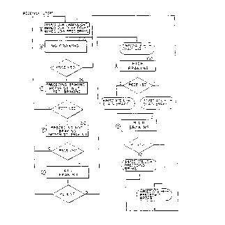
Fig. 3 is an algo-ill,n,ic state mechine logic diagran. of the l,ans.t-iller portion of
a preferred emboJi.-~el)t of the invention;
10 Fig. 4 is an algo~ill.,-.ic state machine logic diagram of the receiver portion of a
preferred e..,l~odl...ont of the invention;
Fig. 5 is a schematic di~grarn of a processing unit of a preferred embodiment ofthe invention.
DESCRIPTION OF THE PREFERRED EMBODIMENTS
A general embodi---e.)t of the present invention can be characterized as a
movable unit or vehicle having installed therein an e"~iller, a detector, a
' ) deceleration indicator, a processor, and a panel indicator. In this embodiment,
the emitter is constructed so as to produce a highly directional RF signal. Signal
frequency is chosen to be very high while output power is chosen to be very
low. A high frequency is chosen to enhance the directional nature of the signal
so that it will be cGnfil-ed to a relatively small area, and a low power output is
chosen so that the effective transmitting distance is approximately six car
lengths. Radio frequency signals are chosen as the mode of transmission and
reception as they are not subject to degradation during adverse driving
conditions as might light waves. The direction of signal emission is
substantially rearward in relation to the vehicle's normal direction of travel so
that only vehicles in a substantially linear chain will be in communication as
opposed to including vehicles adjacent the chain.
~MEI~DED SHEEr
- w 2145g7~ PCT/lJS 93/Og25 6
g IPE~4/US 1 1 OCT t994
The detector is constructed similar to the emitter so as to have greatest
sensitivity in a direction substantially forward in relation to the vehicle's normal
direction of travel so as to receive RF signals transmilleJ by e,.,iller equipped
vehicles forward of it and within the range of signal transmission. the
decel~ration indicator provides information relating to a negative change in
velocity of the vehicle, and be conveniently associated with the vehicle's
braking system. A processing unit is coupled to the ~---iller, detector, and
deceleralion indicator, and operates to interpret the incoming signol and provide
the vehicle operator with information pertaining to vehicles preceding him or her
via the panel indicator and appropriately update the incoming signal for
retra..s...ission via the a...iller.
In the vehicle chain illusl-al~d in Fig. 1, each panel indicator 30a-c
displays to the motorist of each corresponding vehicle information about his or
her vehicle (is she in a chain~, about the vehicle directly preceding her (has that
15 motorist applied his brakes), and about the vel.icles precad:ng the followed
vehicle (have any brakes been applied by motorists that aren't associated with
the i,n",ediately preceding vehicle in the chain). The aforementioned conditionsare indicated by lamps 34, 36, and 38 on each panel indicator 30.
"Chain Formed" lamp 34, which may be white in color, informs the
2~ motorist if he or she is part of a chain of vehicles, i.e., two or more. "Chain
Brake" lamp 36, which may be blue in color, informs a motorist that some
motorist preceding the followed vehicle has applied his or her brakes and that it
may be necessary to exercise caution, especially if a hazard has not yet been
identified. "Brake" lamp 38, which may be red in color, informs the motorist if
25 the brakes of the iri"..ed;ately preceding vehicle have been applied.
Also illustrated in Fig. 1 is the state of information transmitted by emitters
1 2a-c. Emitters 1 2a-c transmit a data signal comprising in this embodiment a
four bit header (1110) which acts as a handshake protocol followed by two bits
of data information, and then by a two bit terminator which can signal the end
30 of the series of information or relate to error detection and/or correction, e.g., a
Ha.",l,ing code. Relating to the transmitted two bits of information, the first bit
,~MENDE~ SH~ET
214587 7 PCT~ 93 / 0 ~
_ ~o . IPE;4/US 1 - CCT
concerns the "Chain Brake" aspect; and the second bit concerns the "Brake"
aspect. Each processing unit 20 controls what data is sent to it respective
emitter 1 2a-c from the data signal received from a corresponding detector 1 Oa-c
and the data obtained from the vehicle itself. The following describes the logicperformed by any processing unit 20 when l,ansn,illi--g a data encoded signal.
Trans".illed bit 1 is set low (a value of "O") unless one of two
conditions are met: Detector 10 receives a valid l.ezd2r (indicating
that the receiving vehicle is in a chain) and a high value for bit 1
(ir.d;cali-)~ that at least one motorist other than the ;mn.ediately
preceding motorist is braking), or detector 10 reeeives a valid
header (indicating that the receiving vehicle is in a chain) and a
high value for bit 2 (indicating that the ~--ot~rist directly preceding
the receiving vehicle is braking). Bit 2 is by default set low unless
the vehiele's brakès are aetivated.
Therefore, the following are repre~ent~live of the disli,)ct information states that
can be trJns,--illed by a vehicle. Also shown is the state of the received signaand the state of a display panel after receipt of the signal. For simplicity, the
terminator bits have been ol~illed and the header bits have been separated by a
dash (-) from the data bits.
Byte received 0000-00: Header False Chain Brake Low Brake Low
Display Panel Status: White Off Blue Off Red Off
Byte sent 1 1 10-00: Header True Chain Brake Low Brake Low
The detector has not received an appro"riate header. This indicates either that
the motorist is not within the effective l~ans"-ission/reception range of a
preceding vehicle equipped with the invention, or that a preceding vehicle does
not have the present invention. Consequently, unless the motorist applies her
brakes (thereby meeting the condition for sending bit 2 high), the emitted signal
has both bits set low. It should be noted that "0000" is chosen for simplicity.
Any combination of bits other than the valid combination, i.e., "11 10" can be
received, but will not be considered a valid header.
Byte received 1110-00: Header True Chain Brake Low Brake Low
~4,M~ND~D SH~E~
21~5877 ÇGr~ 93~t~"r r
-
11 IPEA/US 1 1 OCT t99~
Display Panel Status: White On Blue Off Red Off
Byte sent 1110-00: Header True Chain Brake Low Brake Low
The detector has received an appropriate header so the motorist is in a chain; no
motorist in the chain is braking in front of him; and the motorist is not braking.
If the motorist was braking, the transn,illed signal would be 1110-11.
Byte received 1 110-01: Header True Chain Brake Low Brake High
Display Panel Status: White On Blue Off Red On
Byte sent 1110-10: Header True Chain Brake High Brake Low
The detector has received an appropriate header so the motorist is in a chain; no
motorist preceJ;n~ the ;.--,ncd;ately preceding vehicle is braking; the i.nmed;ately
preceding motorist is braking; and the motorist is not yet braking. If the
motorist was braking, the ll~.ls",illed signal would be 1110-11.
Byte received 1110-10: 1 leedar True Chain Brake High Brake Low
Display Panel Status: White On Blue On Red Off
Byte sent 1110-10: Header True Chain Brake High Brake Low
The detector has received an appropriate header so the motorist is in a chain; amotorist in the chain other than the immediately preceding motorist is braking;
and the motorist is not braking. If the motorist was braking the transmitted
signal would be 1 1 10.1 1
~') Byte received 1110-11: Header True Chain Brake High Brake High
Display Panel Status: White On Blue On Red On
Byte sent 1110-10: Header True Chain Brake High Brake Low
The detector has received an appropriate header so the motorist is in a chain; amotorist other than the immediately preceding motorist in the chain is braking;
the in",.eJiately preceding motorist is braking; and the motorist is not braking.
If the motorist was baking, the tra.)s",illed signal would be 1110-11.
From the foregoing, it can be seen that two distinct functions are
performed by the processing unit -- display control and emitter control. Figs. 3and 4 show the logic performed by the processing unit. The three digit
numerals represent distinct states that the processing unit must address. The
illustrated logic permits the design and construction of suitable electronics for
AM~ ED 51IEFr
CA 0214~877 1999-03-17
From the foregoing, it can be seen that two distinct
functions are performed by the processing unit -- display
control and emitter control. Figs. 3 and 4 show the logic
performed by the processing unit. The three digit numerals
represent distinct states that the processing unit must
address. The illustrated logic permits the design and
construction of suitable electronics for carrying out functions
required by the invention. Fig. 5 represents a simple design
for carrying out the logic using readily available NAND and NOR
gates, and flip flops. Flip flops A, B, and C represent the
input logic, flip flops CL, CB, and PB represent memory for
"Chain Formed," "Chain Brake,ll and "Brake," and flip flops D,
E, and F represent the output logic. Flip flop UC represents a
control logic for a rear mounted blue light which will be
discussed below.
Turning then to a more complex example, in Fig. 2 a first
vehicle D has no vehicles in front of it and therefore cannot
receive a valid header. Consequently, display panel 3Od has no
lamps illuminated. In addition, the motorist of vehicle D is
not braking so the transmitted byte is "1110-00".
A second vehicle E receives the signal transmitted by
emitter 12d via detector lOe. Upon signal processing by
processing unit 20e, display panel 30e of vehicle E is
activated and the "Chain Formed" lamp 34 is caused to
illuminate. Because received bits 1 and 2 are low, neither the
"Chain Brake" lamp 36 nor the "Brake" lamp 38 is caused to
illuminate. The motorist of vehicle E, however, has determined
that deceleration and/or braking is necessary and has therefore
applied her brakes. Consequently, processing unit 20e causes
emitter 12e to send bit 2 high, i.e. "01", to indicate that the
motorist of this vehicle has applied her brakes.
Vehicle F receives the "1110" header and the "01" data
information and processing unit 20f determines that the vehicle
is part of a chain because it has received a header and that
there are no vehicles ahead of vehicle E that are braking
because bit 1 was received low. Furthermore, it has determined
that the motorist of vehicle E is braking because bit 2 was
received high. Therefore, control panel 30f has illuminated
~r~
CA 02145877 1999-03-17
12a
the "Chain Formed" lamp 34 and "Brake" lamp 38. Simul-
taneously, processing unit 20f sends bit 1 high because one of
the
~ ,. . .
: ~, ,, ".. .
4 5 ~ 7 ~ fSCj,~ 93/ ?25tC
13 IPEA/US ~ 1 OCT 1994
conditions neces~v-~ for se..Jin~ bit 1 high has been met: ~,rocess;n~ unit 20f
received a header and bit 2 high. Recause the ,llotGriat of vehicle F has not
~pplied his brakes, ~ lall.iLl~d bit 2 is low.
Vehicle G receives the header "1110" and the "10" data information and
process;.,y unit 20g dete.,..ines that the vehicle is part of 8 chain bec~use it has
received a valid header and that there is at least one motorist ahead of vehicle F
that is brakinQ because bit 1 was received high. Further~..ore, it has deterl,-ined
that the motorist of vehicle F is not t"akiny bec~se bit 2 was receivcd low. In
turn, processin~ unit 209 c~!~ses panel 305 to illu,..;nate the "Chain ro"ned"
Iamp 34 and "Chain Brake" lamp 38 and sends bit 1 high because one of the
condiliGns necessary for sending bit 1 high has been met: processing unit 209
has received bit 1 high. And beca~se the motorist of vehicle G has applied her
brakes, trans".illed bit 2 is sent high.
- ~inally, vehicle H, the last vehicle in the chain, receives the header
1~ "1 1 10" and nl 1 n data information and processing unit 20h determines that the
vehicle is part of a chain because it has received a valid header, that there is at
least one motorist ahead of the immediately preceding vehicle that is braking,
snd that the motorist of vehicle G is applying her brakes. Consequently,
processing unit 20h causes panel 30h to illuminate all three lamps 34, 36, and
7~ 38 and sends bit 1 high and bit 2 low ~because the motorist of vehicle H is not
yet braking).
It should be noted that this motorist of vehicle H is aware of vehicle E's
deceleration as soon as that motorist applies his or her brakes. The motorist ofvehicle H does not have to wait for possible action by the motorists of vehiclesF or G to apply brakes to know that a pote"lially hazardous condition exists. Ina chain with 10 vehicles where the first vehicle is braking, the present invention
will provide the motorist at the end of the chain with this information a full four
secor,Js earlier than by relyin3 a on human reaction chain.
The foregoing disclJssion was directed primarily towards multiple vehicles
moving at high speeds in close proximity to one another. tlowever, the
preferred en~t,od;,..ent atso provides an enhanced means for detecting a stalled
4.~1tA~ r~r
,"~, . , ... , , . , . ... ~ . ... , . .. " . ., .. . . . " . . ... ... . . .... .. ...... . ........ ..
. . . . . .. ... .... ... . . .. .
- 7 ~ ;7~t-' 93 /~ 5 G
14 ~P~JS 1 ~ OCT ijS4
vehicle ecl-uipped wim the i.~ .lliGn if its e.,-er~cncy ~:ashe.s have been
activated. To better iliustrate, the following example is provided.
A disabled vehicle is partially on the side of a road. The ~--utori~ has
teu.pc._.ily left her vehicle to summon aid. Assume that the roads are slippery
and the v~c~lhcr is foggy with visibility less than 50 ..._I_ri. The Inoluri .l has
activated her vehicle's e",er~e..cy flashers ll.e(~by causing the plocessing unit
to set t,--ns...illad bit 2 high. In aJ.liliG.), activation of the e...e~tncy flashers
c~ses the RF a.~ lir;cr of the inve..liGn to increase output power, ll.L.eby
i. .craasi. .y the
~,;
, ,
. .. , , .. .. ~ . . . . .. .. . . . . . .. . . . . . . . . . ..
CA 0214~877 1999-03-17
14a
distance within which a similarly equipped vehicle may receive
the transmitted signal.
At a distance of approximately 100 meters, an approaching
vehicle will begin to receive the transmitted header and bit 2
high. Consequently, the display panel of the approaching
vehicle will indicate that a chain has formed by illuminating
the "Chain Formed" lamp, and will also indicate that the
disabled vehicle has been braked by illuminating the "Brake"
lamp. Even if there is a vehicle between the disabled vehicle
and the motorist, the display panel will illuminate the "Chain
Formed~' and "Brake" lamps, assuming the intermediate vehicle is
also equipped with the invention. Because RF signals do not
degrade in situations where visible light does, the approaching
motorist knows that he has entered a chain and that brakes or
the like are being regularly applied by a vehicle directly
ahead, or that a vehicle has its emergency flashers activated.
Should another vehicle be following this motorist, their panel
will indicate that some motorist ahead is regularly applying
his or her brakes, or that someone has activated their
emergency flashers and that extreme caution should be
exercised. This is a situation wherein the "Chain Brake"
indicator is very beneficial -- even in a situation where a
unit in the "chain" is stationary.
Even if a vehicle's emergency flashers have not been
activated, the preferred embodiment provides a means for
detecting any vehicle equipped with the invention and whose
ignition system is energized when approached from the rear of
that vehicle. Because the invention and more particularly the
preferred embodiment continuously sends at least the header
portion of the transmitted byte, any vehicle equipped with the
invention, and approaching from the rear of a transmitting
vehicle, will receive the header and indicate to the motorist
that his or her vehicle is in a chain. While detection of a
valid header indicates that a chain has formed, detection of
the valid header when there are no other visual or audible cues
to indicate the presence of another vehicle provides the
motorist with more, and perhaps critical, information relating
to upcoming vehicles that might otherwise be undetected. In
CA 0214~877 1999-03-17
14b
adverse weather conditions, this information can be extremely
beneficial even without receipt of a "Chain Brake" or "Brake"
bit.
X
wo g4/08322 2 1 4 5 8 7 7 PCI/US93/09256
To illustrate, say in the above described scenario that the motorist has slid
off the road and has become unconscious. His vehicle is stalled and the
emergency flashers have not been activated. Visibility has now decreased to lessthan 5m. Because his ignition is still energized, his emitter is still transmining a
5 header signal. An approaching vehicle traveling at an appropriately slow speedfor the weather conditions will encounter the Iransmilled signal at approximately
25m and consequently the "Chain Formed" lamp will illuminate. The fact that the
motorist is now part of a chain in such adverse weather conditions and the fact
that the motorist cannot visibly detect the immediately preceding vehicle provides
10 the motorist with enough information so as to indicate that she should exercise
extreme caution.
The inventor acknowledges that the present invention is directed towards
each vehicle having the invention. However, the inventor has provided a means
for motori~ls following an invention equipped vehicle to benefit from its presence.
15 A rear deck mounted blue light is coupled to the processing unit and is activated
by the same mechanism . In this manner, a vehicle following such an equipped
vehicle could observe an illumined blue light, thereby indicating to the following
motorist that if brake lights are not seen, the observed vehicle is part of a chain
and that some motorist of a vehicle in the chain has applied his brakes. While the
20 following motorist could not t,ansmit this information to any vehicles following him,
the motorist benefits from the information possessed by the observed vehicle.
In another embodiment of the present invention, a more complex system is
proposed that permits the signal emanating from emitter 12 to contain information
beyond the header plus two a bit signal. For example, the emilled signal can be
25 a multiple word binary signal. In this manner, words of information can be sent in
packets.
In this alternative embodiment, information in addition to "Chain Formed",
"Chain Brake", and "Brake" would be sent. To illustrate, each vehicle would havean on-board computer that contains information about that vehicle: the number
30 and identity of units in the chain, the number and identity of braking units in the
chain, the length of the chain of units, the average velocity of the units, and mass
of the chain, as well as other non-operational information such as vehicle
~81~TllrE S~EE~
WO 94/08322 PCI'/US93/09256
214~7'1 16
identification and motorist information. With this information, a motorist receiving
such an information packet could be informed as to whether he or she is driving
in a safe manner for the particular chain that he or she is a part. Another practical
use of this information would be to lrai ,s~er relative velocity information to a
5 vehicle's cruise control. The cruise control would increase or decrease the
vehicle's velocity in response to the information received about the chain.
The inventor has contemplated the ability of the present invention to send
and receivc such data communication bi-directionally. In this embodiment, the
complex form of the invention is utilized in addition to a forwardly directed emitter
10 and a rearwardly directed detector. In this manner, each vehicle comprises a
node in the communication network. By utilizing a standard communications
protocol such as ISO X.400, each node could communicate to an adjacent node
which would then pass this information bi-directionally through the chain of
vehicles. The motorist or occupant of any vehicle in the chain could specify what
15 information was to be transmitted and what information was to be received to or
from the chain, or to or from any vehicle in the chain. An enhanced display unitsuch as a CRT will enhance the benefits associated with this embodiment of the
invention.
~SmUTE SHEEr