Sélection de la langue

Search

Sommaire du brevet 2146927 

Énoncé de désistement de responsabilité concernant l'information provenant de tiers

Une partie des informations de ce site Web a été fournie par des sources externes. Le gouvernement du Canada n'assume aucune responsabilité concernant la précision, l'actualité ou la fiabilité des informations fournies par les sources externes. Les utilisateurs qui désirent employer cette information devraient consulter directement la source des informations. Le contenu fourni par les sources externes n'est pas assujetti aux exigences sur les langues officielles, la protection des renseignements personnels et l'accessibilité.

Disponibilité de l'Abrégé et des Revendications

L'apparition de différences dans le texte et l'image des Revendications et de l'Abrégé dépend du moment auquel le document est publié. Les textes des Revendications et de l'Abrégé sont affichés :

  • lorsque la demande peut être examinée par le public;
  • lorsque le brevet est émis (délivrance).
(12) Demande de brevet: (11) CA 2146927
(54) Titre français: OEIL D'ANCRAGE POUR BACHES ET ASSIMILES
(54) Titre anglais: AN ANCHORING EYELET FOR TARPAULINS AND SIMILAR COVERINGS
Statut: Réputée abandonnée et au-delà du délai pour le rétablissement - en attente de la réponse à l’avis de communication rejetée
Données bibliographiques
(51) Classification internationale des brevets (CIB):
  • E04H 15/32 (2006.01)
  • A44B 13/00 (2006.01)
  • E04G 5/12 (2006.01)
  • E04G 21/28 (2006.01)
(72) Inventeurs :
  • SõLBECK, PETER (Danemark)
(73) Titulaires :
  • POLYSHEET A/S
(71) Demandeurs :
  • POLYSHEET A/S (Danemark)
(74) Agent: GOWLING WLG (CANADA) LLP
(74) Co-agent:
(45) Délivré:
(86) Date de dépôt PCT: 1993-09-30
(87) Mise à la disponibilité du public: 1994-04-28
Licence disponible: S.O.
Cédé au domaine public: S.O.
(25) Langue des documents déposés: Anglais

Traité de coopération en matière de brevets (PCT): Oui
(86) Numéro de la demande PCT: PCT/DK1993/000314
(87) Numéro de publication internationale PCT: WO 1994009232
(85) Entrée nationale: 1995-04-12

(30) Données de priorité de la demande:
Numéro de la demande Pays / territoire Date
1278/92 (Danemark) 1992-10-20
1564/92 (Danemark) 1992-12-28

Abrégés

Abrégé anglais


An anchoring eyelet for tarpaulins and similar coverings of a thermoplastic foil material is designed as a substantially an-
nular disc (I) made of plastic. The eyelet has an eyelet opening (2) and is designed in its peripheral part with increased resiliency
by means of indentations which may be formed by radially extending resilient tongues (3) or lobes. This avoids any tendency of
the eyelets to become detached after being pressed in, while forming notches at heavy loads.

Revendications

Note : Les revendications sont présentées dans la langue officielle dans laquelle elles ont été soumises.


P A T E N T C L A I M S
1. An anchoring eyelet for tarpaulins and similar
coverings of a thermoplastic foil material, which eyelet
is designed as a relatively thin, flat and substantially
annular disc (1) of plastic material provided with an
eyelet opening (2), c h a r a c t e r i z e d in that
the peripheral part of the eyelet disc is designed with
indentations to provide increased resiliency to said
peripheral part.
2. An anchoring eyelet according to claim 1,
c h a r a c t e r i z e d in having radially extending
resilient tongues (3) or lobes at the periphery of the
eyelet disc (1).
3. An anchoring eyelet according to claim 2,
c h a r a c t e r i z e d in that the tongues (3) are
evenly distributed along the circumference of the disc
(1) and have a distance (b) between their outer ends
corresponding substantially to the width (a) of each
tongue at its foot.
4. An anchoring eyelet according to claim 3,
c h a r a c t e r i z e d in that the radial length (c)
of each tongue (3) is 5-15 per cent, preferably 10 per
cent, of the maximum diameter of the eyelet disc between
diametrically opposite tongue tips.
5. An anchoring eyelet according to claim 3 or 4,
c h a r a c t e r i z e d in that the indentations (4)
between the tongues have rounded bottoms (5).
6. An anchoring eyelet according to any one of the
preceding claims, c h a r a c t e r i z e d in that
the thickness of the eyelet disc (1) is smaller at the
periphery than at the internal edge around the eyelet
opening (2).
7. An anchoring eyelet according to claim 6,

c h a r a c t e r i z e d in that the thickness of the
eyelet disc (1) decreases substantially evenly towards
the periphery of the disc.
8. An anchoring eyelet according to claims 2 and
7, c h a r a c t e r i z e d in that the individual
tongues (3) or lobes (3) have a substantially lens-
shaped convex cross-sectional profile at right angles
to the corresponding radius of the eyelet disc.
9. An anchoring eyelet according to any one of the
claims 3-5 and 8, c h a r a c t e r i z e d in that
further cuts in the form of holes (8) have been formed
in the resilient tongues or lobes (7).
10. An anchoring eyelet according to any one of the
preceding claims, c h a r a c t e r i z e d in that
the eyelet disc (6) is designed with a reinforcing ring
(10) around the eyelet opening (9).

Description

Note : Les descriptions sont présentées dans la langue officielle dans laquelle elles ont été soumises.

21~ 27
An anchoring eyelet for tarpaulins and similar coverings
The invention rela~es to an anchoring eyelet for
~arpaulins and similar coverings of a thermoplastic foil
material, which eyelet is designed as a relatively thin,
flat and substantially annular disc of plastic material
provided with an eyelet opening.
Tarpaulins of a thermoplastic foil material,
possibly with a net reinforcement, is used extensively
for covering scaffolding in connection with construction
10 works and for numerous covering purposes, for example
for protection of materials and equipment stored out in
the open.
For the purpose of fastening to su~porting struc-
tures or interconnection, the tarpaulins are provided
15 with anchoring eyelets which are pressed into the foil
material in direct connection with the extrusion such
as is known from international patent application No.
W0 91/00801
The tarpaulin eyelets used so far are shaped as
20 relatively thin and stiff annular discs having a
circular, relatively sharp-edged outer periphery.
~ or tarpaulins with inserted eyelets of this type
there may be a certain risk of notch formation at the
eyelet edges, partly in connection with the pressing of
25 the eyelets into the foil material, the consequence of
which is that at later heavy loads, for example wind
loads and tensile infllle~cP~ on the eyelets from the
anchor straps, the eyelets risk becomi~g detached from
the foil material.
This problem is remedied according to the invention
through a design of anchoring eyelets which are charac-
terized in that the peripheral part of the eyelet disc
is designed with indentations to provide increased
resiliency to said peripheral part.
~ .
.

-
219;692
la
For conventional barrel type eyelets intende to be
fastened in leather and similar materials by clenching
it is known from US-A-872,237 to provide an outwardly
turned flange portion forming the head of the eyelet
5 with slots forming a series of petals which can be
individually seated in the material to allow an even
setting of the eyelet also in presence of a foreign
substance on the material.

W O 94/09232 PC~r/D K93/00314
21~S927
The design of the peripheral part of the eyelet
disc with increased resiliency through the provision of
indentations has proved in practice to ~li mi nate or at
least highly reduce the above tendency to notch forma-
5 tion, as transversely acting load forces seeking todetach the tarpaulin from the eyelets are substantially
transformed into shear forces in the plane of the
tarpaulin, because the peripheral edge zone of the disc
acts as a supple joint between the relatively stiff
10 middle part of the eyelet disc and the surrounding foil
material of the tarpaulin.
The indentations may be designed in various ways.
In a very simple embodiment, the increased suppleness
may thus be obtained by designing a ring of holes of an
15 arbitrary shape within the periphery of the disc.
However, a preferred embodiment is characterized
in that indentations are formed by radially extending
resilient tongues or lobes at the periphery of the
eyelet disc.
This also entails the further advantage that the
external peripheral length of the eyelet discs is
increased in consequence of the radially ext~ing
tongues.
The desired resiliency of the peripheral part of
25 the eyelet disc may further be increased by designing
further openings in the form of holes in the resilient
tongues or lobes.
In comparison with conventional eyelets, which are
often exposed to considerable wear at the eyelet opening
30 edge despite their implementation in a relatively stiff
material, the increased resiliency of the peripheral
part of the disc opens up a favourable possibility of
reinforcement of the central part of the disc around the
eyelet opening, for example by means of a reinforcing
35 ring.

W094/09232 PCT/DK93/00314
2 ~ 7
The anchoring eyelets according to the invention
may be pressed into the foil material directly in
~onnection with the extrusion, while the material is
still soft, but may also be fastened by heat s~ ng or
5 adhesion. IndepPn~ently of the fastening method it may
be appropriate for the indentations between the tongues
to have a rounded bottom, in order to ensure sturdy
sealing to the foil material.
The invention will now be explained in further
lO detail with reference to the drawings, in which
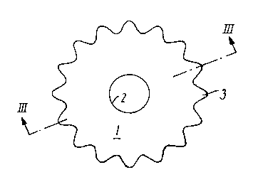
Fig. l is a plane view of an embodiment of an
anchoring eyelet according to the invention,
Fig. 2 is an enlarged partial view of the eyelet
of Fig. l,
Figs. 3 and 4 show sectional views along the lines
III-III and IV-IV of Figs. l and 2, respectively, and
Figs. 5 and 6 show a modified embo~;~e~t.
The anchoring eyelet shown in Fig. l is designed
as a substantially annular disc l having an eyelet
20 opening 2 which is shown in a position in the centre of
the disc l, but which may also be in an off-centre
position.
In accordance with the invention, the peripheral
part of the eyelet disc l is designed with increased
25 resiliency by means of indentations which, in the
embodiment shown, are formed by radially ext~n~;ng
resilient tongues 3 at the periphery of the disc.
The disc l is made of a suitable thermoplastic
material such as l; ne~r low-density polyethylene (LLDP),
30 and the resiliency of the tongues 3 is increased by the
fact that the thickness of the disc l decreases from the
inner edge at the eyelet opening 2 towards the periphery
of the disc at the end of the tongues 3, such as it
appears from Fig. 3. The tongues 3 are preferably evenly
35 distributed along the circumference of the disc l, for
.

W094/09232 PCT/DK93/00314
6~2~ _
example at an angle of division v of 22.5 as shown in
Fig. 2, corresponding to a total of 16 tongues.
The shape of the individual tongues 3 may suitably
be so that the width a of the tongue is substantially
5 equal to the distance b between the ~freely extending
ends of neighbouring tongues, corresponding to an angle
u of 45 between the two side edges of the tongue.
The radial length c of each tongue is adapted to
the periphery of the disc and may be from 5 to 15 per
lO cent, preferably about lO per cent thereof, wh~ch has
proved to give a suitable elastic deforma~ility of the
tongues.
To ensure sturdy sealing at the fastening of the
eyelets in a thermoplastic foil material, which may be
15 done either by pressing in connection with extrusion of
the material as explained in said international patent
application, or by subsequent heat sealing or adhesion,
the indentation 4 between the tongues is preferably
designed with a rounded bottom as shown in Fig. 2.
The tapering of the disc towards the periphery is
also, as shown in Fig. 3, implemented at the bottoms 5
of the tongues, and correspondingly, the individual
tongues 3 have a lens-shaped convex cross section as
shown in the enlarged sectional view in Fig. 4, so that
25 all the way round along the circumference, the disc 1
exhibits a uniformly slight material thickness adapted
to the foil in which the eyelets are to be placed.
In the modified embodiment shown in Figs. 5 and 6,
the resiliency of the peripheral part of the eyelet disc
30 6 is further increased by circular holes 8 being formed
in the radially exten~;ng tongues 7, of which there are
eight in this embodiment.
At the same time, the strength of the disc 6
immediately around the eyelet opening 9 is increased by

W094/09232 21~ 6 9 2 7 PCT/DK93/00314
means of a reinforcing ring 10, which may, for example,
be made of metal.

Dessin représentatif
Une figure unique qui représente un dessin illustrant l'invention.
États administratifs

2024-08-01 : Dans le cadre de la transition vers les Brevets de nouvelle génération (BNG), la base de données sur les brevets canadiens (BDBC) contient désormais un Historique d'événement plus détaillé, qui reproduit le Journal des événements de notre nouvelle solution interne.

Veuillez noter que les événements débutant par « Inactive : » se réfèrent à des événements qui ne sont plus utilisés dans notre nouvelle solution interne.

Pour une meilleure compréhension de l'état de la demande ou brevet qui figure sur cette page, la rubrique Mise en garde , et les descriptions de Brevet , Historique d'événement , Taxes périodiques et Historique des paiements devraient être consultées.

Historique d'événement

Description Date
Inactive : CIB de MCD 2006-03-11
Demande non rétablie avant l'échéance 1998-09-30
Le délai pour l'annulation est expiré 1998-09-30
Réputée abandonnée - omission de répondre à un avis sur les taxes pour le maintien en état 1997-09-30
Demande publiée (accessible au public) 1994-04-28

Historique d'abandonnement

Date d'abandonnement Raison Date de rétablissement
1997-09-30
Titulaires au dossier

Les titulaires actuels et antérieures au dossier sont affichés en ordre alphabétique.

Titulaires actuels au dossier
POLYSHEET A/S
Titulaires antérieures au dossier
PETER SõLBECK
Les propriétaires antérieurs qui ne figurent pas dans la liste des « Propriétaires au dossier » apparaîtront dans d'autres documents au dossier.
Documents

Pour visionner les fichiers sélectionnés, entrer le code reCAPTCHA :


Pour visualiser une image, cliquer sur un lien dans la colonne description du document. Pour télécharger l'image (les images), cliquer l'une ou plusieurs cases à cocher dans la première colonne et ensuite cliquer sur le bouton "Télécharger sélection en format PDF (archive Zip)" ou le bouton "Télécharger sélection (en un fichier PDF fusionné)".

Liste des documents de brevet publiés et non publiés sur la BDBC .

Si vous avez des difficultés à accéder au contenu, veuillez communiquer avec le Centre de services à la clientèle au 1-866-997-1936, ou envoyer un courriel au Centre de service à la clientèle de l'OPIC.


Description du
Document 
Date
(aaaa-mm-jj) 
Nombre de pages   Taille de l'image (Ko) 
Page couverture 1995-08-07 1 16
Abrégé 1994-04-28 1 46
Description 1994-04-28 6 203
Revendications 1994-04-28 2 62
Dessins 1994-04-28 2 20
Dessin représentatif 1998-02-11 1 3
Courtoisie - Lettre d'abandon (taxe de maintien en état) 1997-10-28 1 185
Taxes 1996-08-16 1 43
Taxes 1995-08-21 1 43
Rapport d'examen préliminaire international 1995-04-12 8 225
Correspondance de la poursuite 1995-04-12 1 21