Note : Les descriptions sont présentées dans la langue officielle dans laquelle elles ont été soumises.
21~7544
-
TOOL SUPPORT AND
PRESENTATION DEVICE
Background and Summary of the Invention
The present invention relates generally to support devices for elongate tools
or tool heads such as the small burs used by dentists. More specifically, the invention
concerns such a device that, when lidded, protectively supports the tools and optionally
permits sterilized cleaning thereof and, when unlidded, presents the tools for easy removal
by popping open and splaying the tools in a frustoconical array. The invention will be
described in a preferred embodiment to be particularly useful with tools such as dental burs.
Dental burs are tiny drill or auger bits which are used by dentists in
combination with high speed drills to ~-lmini~ter dental procedures. These procedures
inclllcle the drilling and filling of cavities resulting from tooth decay. The burs are very
small and they come in many shapes. For instance, to enable a dentist to perform intricate
site-specific excavation, a minute drill point may be required. Alternatively, to perform
relative large-scale excavation, a larger point or drill tip may be required.
Typically, these burs are characterized as having cylindrical bottom portions.
The cylindrical bottoms are usually received in and fixedly secured in the drill's chuck.
Thereafter, various drilling procedures may be undertaken. Because a dentist may require
a number of different burs during any one procedure, it is desirable to store the burs in a
20 central location, such as a bur holder. It is also desirable to be able to conveniently and
easily access the burs throughout the ~lministration of a dental procedure. It is of
paramount importance that the burs remain in a clean, sterilized condition. Having many
densely packed burs in a holder increases the chances that a bur will be inadvertently
contacted and thereby cont~min~ted.
Thus, it is desirable to have a device which centrally holds or stores dental
burs and presents them, on demand, in a fashion which greatly reduces the chances of
inadvertent cont~min~tion and facilitates their extraction from the holder.
21~7~4~
Conventional tool support devices may be characterized as follows. U.S. Pat.
No. 4,327,060, entitled "STERILIZING-CONTAINING DEVICE FOR DENTAL TOOLS"
issued to Nisii, discloses an open top container for receiving a dental tool support in the
form of an open-bottom cylinder provided with threads around its upper and lower ends
which are engaged in threads in the upper end of the container. The open-bottom cylinder
is provided with plural bores into which various dental burs are received. The burs are
received such that their top portions, or drill heads, remain within the container, in a
substantially vertical orientation relative to the base of the container. Removing the burs
from the container is complicated by the fact that only a short portion of each bur's
10 cylindrical shaft rises above the cylinder. This is undesirable because the burs are presented
for removal in a crowded confi~,uration. Moreover, only a small portion of each entire bur
is presented for removal. This is undesirable because, while one bur is removed, another
adjacent bur may be inadvertently plucked thereby increasing the chances of, among other
things, cont~rnin~tion.
U.S. Pat. No. 2,978,110 entitled "RACK-LIKE HOLDER FOR SMALL
ARTICLES" issued to Haskins discloses a case with a hemispherical holder body for holding
articles such as dental drills. Specifically, Haskins discloses a cylindrical holder having a
base, a cover, and a holder body disposed within the base having plural fingers for holding
articles such as dental drills, pencils, lipsticks, and spools of thread. The body may be flexed
20 inwardly or outwardly after the manner of a diaphragm. Centrally disposed on the holder
is a stem which extends upwardly. When the cover is closed, the holder is collapsed within
the base with a bottom portion thereof resting on the base. When the cover is removed, the
stem may be grasped by the user and the holder pulled upwardly to extend it outwardly from
the base wherein the articles held in the fingers are exposed and accessible.
Haskins discloses, in one embodiment (see Fig. 5), a coil spring interposed
between the base and the holder to prevent the diaphragm from resting on the base due to
the weight of articles held in the fingers. The holder in Haskins does not automatically
214754~
present the tools upon removal of the container's cover. Rather, the user must physically
grasp the stem on the holder and pull the stem upwardly to present the tools. The tools are
thereafter presented in a substantially vertical orientation relative to the base. By having
to reach into the holder to extract held tools, the chances of cont~min~tion are greatly
increased. Further, when the tools are in the stored position within the container (see Fig.
1), the respective weights thereof tend to draw the top portions of the tools toward the
center where they may inadvertently contact one another.
To minimi7e the risk of cont~rnin~ting the tools following sterilization, and,
to facilitate the extraction thereof, it is desirable to have the tools automatically presented
10 in an outwardly arrayed or frustoconical manner. Neither Nisii nor Haskins provides for the
tools to be automatically presented in a splayed manner or frustoconical array. Rather, both
display or present the tools in a vertically orientation relative to the base with either the tool
heads or tails in close proxil-~iLy. This is inconvenient and increases the chances of
inadvertently touching thereby cont~rnin~ting adjacent tools.
Moreover, the holder disclosed in Haskins is a solid disc-like structure with
no provisions to promote the relative independent movement of the held tools. It is
desirable that the held tools be able to move relatively independent of one another in their
held positions to decrease the chances of one tool inadvertently cont~Tnin~ting another tool
or accidentally puncturing a dentist's glove. Without relative independent movement
20 between adjacent tools, when one tool is removed, any downward force perpendicular to the
diaphragm plane, such as that caused by the dentist's hand, will cause other adjacently held
tools to be drawn toward the point of application of the force.
Further, when sterilizing held tools such as dental burs, it is necessary that all
portions of the bur, specifically the bottom held portions be sterilized otherwise there is a
risk that all of the burs will be cont~rnin~ted. The fingers disclosed in Haskins into which
the bottom portions of the articles, i.e. dental burs are held, provide for a firm, flush fit such
2147544
that if the held articles were to be sterilized or cleansed, the bottom portions thereof would
remain unsterilized.
With these problems in mind, it is an object of this invention to provide a
device to hold and support plural tiny tools, such as dental burs, and to present the tools,
upon demand, in an arrangement providing convenient access to the user and reducing the
chances of inadvertent cont~min~tion. Such a device will have a flexible diaphragm with
characteristics enabling it to change its shape to effect the presentation of held tools.
It is another object of this invention to employ the use of a diaphragm to hold
tiny tools, wherein the diaphragm employs a construction to promote the relative
10 independent movement of the held tools. The relative independent movement of the tools
while in their held position greatly reduces the chances that adjacent tools may contact one
another or be drawn toward a user's hand when a tool is removed.
It is another object of this invention to provide a device to hold and support
plural tiny tools (such as dental drill bits) while they are being sterilized and cleaned. Such
a device will have holders or collets for receiving and holding each tool, and each collet will
have a cross-section which allows for the entire tool, specifically the bottom portions, to be
sterilized.
It is yet another object of this invention to provide a device to hold, support
and present plural tiny tools, which device may be operated using only one hand. Such a
20 device will enhance greatly the convenience with which tools may be inserted and extracted,
or loaded and used.
It is a further object of the invention to provide a device for holding and
displaying tools which has a reduced height so that such device is more compatible with
sterilization and other procedures.
In sl1mm~ty, the invention in its preferred embodiment achieves these and
other objects in the form of a tool support and presentation device having a circular base
with a central, vertical spindle extending upwardly and a circular or disk-shaped cover with
21475~4
a central, cylindrical barrel designed to mate with the base's spindle. Within the base and
extending around the bottom of the spindle is a coil spring. The spring presses upwardly
against a flexible, resilient circular disc. This circular disc has flanges that are tucked under
the shoulder on the top edge of the base. Collets of square cross section are held within
holes in each flange, and each collet holds one tiny tool.
When the cover is removed, the spring urges the resilient circular disc
upwardly and the tiny tools splay out to allow easy digital access to each of them. The cover
presses the spring down when it is mounted on the vertical spindle, which has a locking
protuberance for mating with a slotted key-hole structure in the cover's barrel. When the
10 cover is in place, the tools move to a substantially vertical orientation and the cover prevents
them from escaping from the device, despite vibration and movement within their collets.
When the device is closed the tools may be cleaned using autoclaving, ultrasonic or other
cleaning techniques. During autoclaving, the square cross section collets provide clearance
and support for the complete cleaning of the tools, which have substantially cylindrical
shafts. Tiny cylindrical tools can be cleaned more efficiently and effectively when held in
a collet having a square cross section.
In one embodiment, a hand-held device is provided with a cylindrical base
having upwardly extending walls defining an opening, an upwardly extending spindle joined
to the base, and a cylindrical cover mounted to the upper end of the spindle. The walls
20 include a recessed portion defining an ~nn~ r shoulder. A resilient diaphragm spanning
the opening defined by the base's walls is fitted at its periphery with an ~nmll~r ring
dimensioned to fit around the base's wall, specifically the recessed portion thereof. The
diaphragm is provided with apertures or collets into which tiny tools may be placed.
Support structure is provided intermediate the ends of the spindle and supports the
diaphragm thereby providing a surface against which the diaphragm may be bent or
stretched.
21~75~4
When the ~nn~ r ring is drawn along the base's wall in the direction of the
base, the diaphragm is bent or stretched over the support and the held tools are presented
in an outwardly arrayed or splayed manner. The resilience of the diaphragm causes it to
rebound or assume its original shape upon cessation of the drawing action by the user. In
its original shape, the diaphragm, and particularly the collets, orient the tools in a vertical
upright manner. In its flexed shape, the diaphragm is bent or stretched and the tools are
presented in a splayed manner.
Embodiments of the present invention may include an offset member mounted
around the spindle for rotation thereabout, having radially outwardly extending selection
10 arms or flanges. A tab connected to one of the selection arms may be shifted relative to
the base, which cause the selection arms to tilt the individual collets so that the overall
height of the device may be reduced.
Usually, dentists wear gloves to protect from viral tr~nsmi~ion to/from the
patient. With prior art tool support devices having the tool heads packed closely together
as they exit the autoclave, often the dentist would have difficulty picking the desired tool
without interfering with an adjacent tool. At worst, the glove might be pricked by a sharp
adjacent tool, and the prophylactic protection of the glove comproll~ised. With the invented
tool support and presentation device, the tools automatically splay for their presentation in
a configuration that, while permitting dense packing for autoclaving, yet are automatically
20 and convelliently separated for selective use.
These and additional objects and advantages of the present invention will be
more readily understood after a consideration of the drawings and the detailed description
of the preferred embodiment.
Brief Description of the Drawings
Fig. 1 is a side-plan view of the invented device shown in its lidded
configuration, made in accordance with its preferred embodiment, with portions of the
device broken away to show detail.
21475~
Fig. 2 is a side-plan view of the device corresponding to Fig. 1 but showing the
device in its unlidded configuration with the supported tools splayed for presentation.
Fig. 3 is a top-plan view of the device corresponding to Fig. 2.
Fig. 4 is a side-plan view of an alternative embodiment of the device with
portions of the device broken away to show detail.
Fig. 5 is a top-plan view of the device corresponding to Fig. 4 along lines 5-5
showing the device with the supported tools tilted therein.
Fig. 6 is a side-plan view of an alternative embodiment of the device with
portions of the device broken away to show detail.
Fig. 7 is a side-plan view of the device corresponding to Fig.6, but showing the
device with the supported tools splayed for presentation with portions of the device broken
away to show detail.
Detailed Description of the Preferred Embodiment
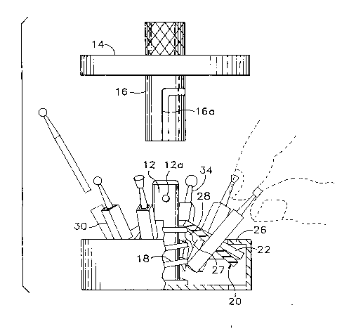
Referring to Figs. 1-3, the device has a cylindrical base 10 defining a plane,
and an inner member shown generally at 11. Base 10 includes a central portion 10_ and an
outer portion lOb. Inner member 11 in accordance with the preferred embodiment of Figs.
1-3 includes an elongate spindle 12 mounted on central portion 10_ and a coil spring 18
received by spindle 12. Cylindrical cover 14 has a centrally mounted cylindrical barrel 16
designed to mate with inner member 11, and more specifically spindle 12. Cylindrical cover
20 14 includes non-abrasive shock-absorbing lining 14_ which both prevents the tools from
escaping the device and protects them while they are held therein.
A resilient shape-retentive diaphragm 20 preferably formed from any suitable
deformable material such as an elastomer, is in the form of a disc mounted on inner
member 11 adjacent the base. Diaphragm 20 has an outer surface 20_, an inner surface
20_, and a central, an intermediate, and a peripheral region 20_, 20, and 20e, respectively.
When diaphragm 20 is mounted on the inner member, inner surface 20_ faces the base and
spring 18 presses upwardly against, or biases, diaphragm 20 at central region 20ç.
214754
~- 8
Diaphragm 20 preferably inchldes plural flanges 22 which extend radially
outwardly from central region 20_ to form intermediate region 20d and peripheral region
20e. The flanges are tucked under an outer member 26, which may take the form of an
inwardly projecting shoulder 26 on the top edge of base 10. Intermediate region 20d
includes apertures 32 each of which receives a collet 30. Collets 30 are elongate and have
square cross sections best shown in Fig. 3, which cross sections are orthogonal to the long
axes of each collet. It will be appreciated that collets 30 may have other polygonal or multi-
linear cross sections such as that of a triangle or pentagon. Each of the flanges is separated
from the other flanges by plural cutout regions, or spaces, 27, most easily seen in Fig 3.
10 Pairs of adjacent spaces promote the relative independent movement of the corresponding
flange by allowing each flange controllably to move up and down, and controllably to twist
slightly, relative to the base without interfering with adjacent flanges. Each space 27
termin~tes at a radially inward extreme with hole structure 28 for further promoting such
relative independent movement (and reducing the tendency of diaphragm 20 to tear).
Although the device has been described as having a cylindrical base and
circular diaphragm, it will be appreciated that the base and diaphragm may come in a
variety of shape and sizes. For instance, the base and diaphragm may be rectangular,
triangular or other preferably regular shapes. Moreover, it is contemplated that coil spring
18 may be a leaf spring or any of a variety of springs or other biasing mech~ni~m,~ capable
20 of urging the central region of the diaphragm upward or otherwise flexing it into a convex
shape.
Referring now to Figs. 1 and 2, it may be seen that diaphragm 20 has two
configurations during different phases of the operation of device 10. Fig. 1 shows diaphragm
20 in its generally planar configuration and Fig. 2 shows the diaphragm in its arcuately
flexed configuration.
In its planar configuration (see Fig. 1), the surface of diaphragm 20 lies in a
plane generally parallel to the plane defined by base 10 and collets 30 extend generally
_ 21~7~
orthogonal to the plane defined by the base, i.e. they are orientated substantially vertically
when the base is on a horizontal support surface. Put another way, in the planar
configuration of diaphragm 20, planes transversing each collet orthogonal to the long axis
thereof are subst~nti~lly parallel to the plane defined by the base.
In its flexed configuration (see Fig. 2), diaphragm 20 is flexed convexly away
from the base such that planes transversing each of the collets orthogonal to the long axes
thereof are relatively ~n~ rly offset from the plane defined by the base. This orients
collets 30 and the tools held therein in a frustoconical array.
When cover 14 is removed, the disc assumes its flexed configuration as spring
18 urges the central region of diaphragm 20 upwardly and tiny tools 34 splay out
frustoconically to allow easy access to each of them. Barrel 16 on cover 14 counteracts the
upward force of spring 18 and presses diaphragm 20 into its planar configuration when the
cover is mounted on spindle 12. Spindle 12 has a locking protuberance 12_ for m~ting,
when so mounted, with slotted key-hole structure 16_ in the cover's barrel. When the cover
is in place, tools 34 are in a substantially vertical orientation relative to the horizontal base,
such as that shown in Fig 1, and cover 14 prevents them from escaping from the device.
The tools may vibrate and move slightly within their collets, but they will not escape the
devlce.
When device 10 is closed, the tools may be cleaned using autoclaving,
20 ultrasonic or other cleaning equipment. During autoclaving, the square cross section of the
collets provides clearance and support for the complete cleaning of the tools, which have
substantially cylindrical shafts. Tiny cylindrical tools may be cleaned more efficiently and
effectively when held in a collet of square cross section. The corners of the collets provide
for the releace of cont~min~n1.c and the flow of fluids due to their non-conforming cross
sections relative to the cross section of the held tools. As discussed above, the importance
with regard to the square cross section is that each tool is free, to some degree, to move
within the collet thereby facilitating cleaning thereof. While collets having square cross
21475~
_
sections are particularly preferred, those of skill will appreciate that the use of collets of any
useful cross section, including a round one, are within the spirit and scope of the invention.
Referring now to Figs. 4 and 5, an adaptation of the preferred embodiment
of Figs. 1-3 which will reduce the overall height of the device may be seen as an offset
member indicated generally at 80. Offset member 80 is mounted on spindle 12 for rotation
thereabout. Member 80 has plural selection arms 82_, 82_, 82_, 82d, 82e, 82f, 82g, 82h, 82:,
and 82i, referred to collectively as selection arms 82 which selection arms are adjacent each
collet. Selection arms 82 extend radially from a central hub 81. Further, a tab 84 is
provided either on one of the selection arms or attached to hub 81 and extends outwardly
through a tab slot 86 in base 10. Tab 84 may be moved arcuately within tab slot 86 thereby
rotating offset member 80 about the spindle such that each of the selection arms 82 tilts a
corresponding one of the collets such that planes transversing each of the collets orthogonal
to the long axes thereof are relatively angularly offset from the plane defined by the base.
By tilting the collets in this way, the overall height of the device is reduced m~king it more
compatible with sterilization and other logistic procedures.
Usually, dentists wear gloves to protect from viral tr~n~mi~ion to/from the
patient. With prior art tool support devices having the tool heads packed closely together
as they exit the autoclave, often the dentist would have difficulty picking the desired tool
without interfering with an adjacent tool. At worst, the glove might be pricked by a sharp
20 adjacent tool, and the prophylactic protection of the glove will have been compromised.
With the invented tool support and presentation device, the tools semi-automatically splay
for their presentation in a configuration that, while pelll~iLIhlg dense packing for autoclaving,
yet are semi-automatically and conveniently separated for use.
Moreover, the individual tools are located each on a flange which underlaps
a shoulder portion of the base. These flanges are provided with apertures in which the
collets are received. Thus, a tiny tool may be placed in each collet and held for cleaning
or storing. Separating each flange is a space termin~ting in hole structure located near a
2147544
central portion of the diaphragm. These spaces and hole structure promote the relative
independent free movement of each flange by allowing each flange to move up and down
and slightly to twist, relative to other adjacent flanges without interfering with them.
Thus, a person desiring to insert or remove a tiny tool from the collet need
only remove the cover, whereupon the central region of the diaphragm is automatically
urged upwardly relative to the base, presenting the collets or tools in an outwardly arrayed
manner. Thereafter, the user may conveniently pluck or insert a tool from or into the
frustoconically arrayed collets. The spaces between the plural flanges allow each flange to
move relatively independently of one another with the result that when a user, e.g. a dentist,
attempts to remove or insert a tool into the collet, any inadvertent downward or lateral
force, such as in a direction perpendicular to the diaphragm or on the collet itself, will cause
only the flange in which the collet is located to bend downwardly. Adjacent flanges will
remain substantially in place and will not be drawn toward the direction of the applied
force, as would be the case if there were no spaces between the flanges.
After the desired tool has been inserted into or removed from the collet, the
cover may be replaced which brings the tools to a substantially vertical orientation for easy
storing. In their stored positions, the tools are held protectively in place by the cover which
also prevents the tools from falling out if the device were to be inverted.
An alternative embodiment, also known as a hand-held embodiment, is shown
in Figs. 6 and 7, generally at 50. Preferably right cylindrical device 50 may be seen to
include a cylindrical base 52 defining a plane, which base has an upwardly extending wall
portion 54 defining an opening. Wall portion 54 includes a recessed portion 56, forming an
~nmll~r shoulder 58. Like the preferred embodiment described above, device 50 has an
inner member 60 that is centrally mounted on base 52 and may be seen to include a spindle
61 and an ~nmll~r support 64. Spindle 61 has first and second ends, 62 and 63 respectively,
with first end 62 joined to the base at a central region thereof. Second end 63is joined to
cylindrical cover 66 which cover may be provided with a lanyard loop 68 for ~tt~hing device
21~75~4
_
50 to a key ring or belt (not shown). Cover 66 includes a non-abrasive shock-absorbing
lining 66_ which both prevents the tools from escaping the device and protects them while
they are held therein. Support 64 is fixedly mounted on spindle 61, intermediate first and
second ends 62 and 63 respectively.
Mounted on base 52 and spanning the opening defined by upwardly extending
wall portion 54 is a resilient shape-retentive diaphragm 70. The diaphragm has inner and
outer surfaces 70_ and 70_ respectively and a central region 70_, an intermediate region 70d
and a peripheral region 70e. Diaphragm 70 is provided with integrally formed collets 90 in
the intermediate region 70d.
An ~nmll~r ring 76, having a diameter slightly larger than the diameter of
recessed wall portion 56, is disposed around that portion and joined to diaphragm 70 at
peripheral region 70e. As a result, the combination of diaphragm 70 and ring 76, (which
may be found integrally therewith) when drawn along recessed wall portion 56 toward base
52 in the direction of Arrow A, causes diaphragm 70 to bend, thereby splaying tools 34 in
a radially outward direction relative to inner member 60. Upon cessation of the drawing
action, tools 34 are returned to their original vertical orientation by the resilient rebounding
of peripheral region 70e of diaphragm 70 in the direction of Arrow B and by the return of
tool-holding intermediate region 70d to the generally horizontal orientation shown in Fig.
6.
The bending or stretching of the diaphragm is enhanced by ~nmll~r support
64 and opposed ~nmll~r clamping member 65. Annular support 64 biases central region 70_
upward in relation to a generally opposing force when ring 76 and diaphragm 70 are drawn
along wall portion 56. Clamping member 65 captures central region 70c of diaphragm 70
between annular support 64 and h~lds central region 70_ firmly in place. When a force in
a direction normal to the plane defined by base 52 and toward the base is m:~ml~lly applied
to ring 76, ~nmll~r support 64 opposingly biases central region 70_ c~n~ing the diaphragm
to bend, thereby splaying the held tools. Diaphragm 70 is held in place during this
21~75~
13
operation by clamping member 65. An ~nmll~r groove 73 in the form of a strain break or
relief is provided to promote localized controlled bending and corner formation.
The hand-held embodiment works along the same principles as the prefel,ed
embodiment of Figs. 1-3 described hereinabove. That is, a user may present the held tools
in an outwardly splayed manner to facilitate removal and replacement from or within a
collet. Holding the device in the palm of one's hand, with the base resting flush thereon,
the thumb and index finger may reach up and engage the ~nn~ r ring to which the
peripheral region of the diaphragm is joined. By pulling downwardly in the direction of the
base, the user exerts a force which bends the diaphragm downwardly outwardly from the
10 ~nmll~r support disposed on the device's spindle, thereby ca~l~ing one or more held tools
to splay outwardly for easy access.
Thus a new and innovative design in a tool support and presentation device
has been disclosed which will both hold tiny tools and present them, upon demand, in an
easily accessible configuration. The structure includes a base having a centrally mounted
spindle and a resilient diaphragm mounted on the spindle, the diaphragm having collets for
holding tiny tools. The diaphragm may be either automatically or m~ml~lly flexed to
present the tools in an outwardly arranged or frustoconical configuration. When
automatically flexed, the diaphragm is conrloll~ed by a spring therebeneath to urge a central
region of the diaphragm upwardly. When m~nll~lly flexed, the diaphragm may be drawn
20 by the user along a direction toward the base where during such drawing a central region
of the diaphragm is held in place relative to the spindle, which drawing causes the
diaphragm to flex and thereby present the tools.
It will be appreciated that the pop-and-splay tool support and presentation
device is not limited in utility to the dental field, but is useful generally in fields where
relatively tiny, plural tools might be closely configured and secured for cleaning and/or
storage and yet presented accessibly and perhaps better splayed in preparation for or in
connection with their use.
214754
"t
While the present invention has been shown and described with reference to
the foregoing preferred embodiment, it will be apparent to those skilled in the art that other
changes in form and detail may be made therein without departing from the spirit and scope
of the invention as defined in the appended claims.