Sélection de la langue

Search

Sommaire du brevet 2147978 

Énoncé de désistement de responsabilité concernant l'information provenant de tiers

Une partie des informations de ce site Web a été fournie par des sources externes. Le gouvernement du Canada n'assume aucune responsabilité concernant la précision, l'actualité ou la fiabilité des informations fournies par les sources externes. Les utilisateurs qui désirent employer cette information devraient consulter directement la source des informations. Le contenu fourni par les sources externes n'est pas assujetti aux exigences sur les langues officielles, la protection des renseignements personnels et l'accessibilité.

Disponibilité de l'Abrégé et des Revendications

L'apparition de différences dans le texte et l'image des Revendications et de l'Abrégé dépend du moment auquel le document est publié. Les textes des Revendications et de l'Abrégé sont affichés :

  • lorsque la demande peut être examinée par le public;
  • lorsque le brevet est émis (délivrance).
(12) Brevet: (11) CA 2147978
(54) Titre français: OSSATURE DE PONT SUSPENDU
(54) Titre anglais: SUSPENSION BRIDGE FRAMEWORK
Statut: Périmé et au-delà du délai pour l’annulation
Données bibliographiques
(51) Classification internationale des brevets (CIB):
  • E01D 11/00 (2006.01)
  • E01D 11/02 (2006.01)
(72) Inventeurs :
  • BROWN, WILLIAM (Royaume-Uni)
(73) Titulaires :
  • STRETTO DI MESSINA S.P.A.
(71) Demandeurs :
  • STRETTO DI MESSINA S.P.A. (Italie)
(74) Agent: SMART & BIGGAR LP
(74) Co-agent:
(45) Délivré: 2001-04-03
(86) Date de dépôt PCT: 1993-10-27
(87) Mise à la disponibilité du public: 1994-05-11
Requête d'examen: 1999-12-02
Licence disponible: S.O.
Cédé au domaine public: S.O.
(25) Langue des documents déposés: Anglais

Traité de coopération en matière de brevets (PCT): Oui
(86) Numéro de la demande PCT: PCT/EP1993/002985
(87) Numéro de publication internationale PCT: WO 1994010386
(85) Entrée nationale: 1995-04-26

(30) Données de priorité de la demande:
Numéro de la demande Pays / territoire Date
MI92A002466 (Italie) 1992-10-28

Abrégés

Abrégé français

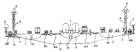
Construction destinée à être utilisée sur un pont suspendu du type comprenant une structure principale essentiellement plate, dont la surface supérieure forme la chaussée sur laquelle circulent les moyens de transport traversant le pont. Cette construction est fixée à un système de suspension formée par une pluralité de poutres verticales (6) reliées à des câbles caténaires (5) ancrés dans les piliers d'extrémités du pont. La construction est constituée d'au moins deux corps longitudinaux en forme de boîte parallèles correspondant à deux chaussées du pont, espacés l'un de l'autre d'une distance égale à leur dimension transversale. Lesdits corps possèdent une section dont le profil est apte à favoriser l'écoulement régulier du vent et ils sont interconnectés, à intervalles réguliers, à l'aide de guides rigides transversaux (4) ayant aussi une forme de boîte et portant à leurs extrémités des moyens permettant leur ancrage dans les poutres de suspension (6).


Abrégé anglais


Framework for a suspension bridge of the type comprising an essentially flat
main structure, the top surface of which
forms the traffic lane for the transport means crossing the bridge, anchored
to a suspension system formed of a plurality of
vertical hangers (6) fixed to catenary cables (5) anchored to end piers of the
bridge. The framework consists of at least two parallel
longitudinal box-like bodies corresponding to two runways of the bridge,
reciprocally spaced by an extent equal to their
transversal dimension. Said bodies have a cross section with a profile apt to
favour the proper flow of the wind stream and they are
interconnected, at regular intervals, by stiff supporting transversal ledgers
(4) having in turn a box-like configuration and carrying at
their ends means for their anchorage to the suspension hangers (6).

Revendications

Note : Les revendications sont présentées dans la langue officielle dans laquelle elles ont été soumises.


CLAIMS:
1. A suspension bridge having a framework comprising a
substantially flat main structure, said main structure having a
top surface which forms a traffic flow lane, a suspension
system formed by a plurality of vertical stays or hangers fixed
to catenary cables anchored to end piers of the bridge, said
framework being anchored to said suspension system, said
framework comprising a plurality of parallel box bodies
extending longitudinally of the bridge and corresponding to two
runways of the bridge, said box bodies being spaced apart a
distance equal to their transverse dimension, and stiff
supporting transverse ledgers by which said box bodies are
interconnected at regular intervals, said box bodies having a
transverse cross section which is an aerodynamic profile.
2. A suspension bridge as claimed in claim 1, wherein
said longitudinal box bodies have upper surfaces that are flat
and under surfaces that are curved with a profile to favor flow
of a wind stream.
3. A suspension bridge as claimed in claim 1, wherein
securement of the framework to suspension hangers is provided
only at the ends of said ledgers.
4. a suspension bridge as claimed in claim 1, having
thereon gratings forming safety runways positioned in free
spaces between the longitudinal box bodies.
5. A suspension bridge as claimed in claim 4, wherein
said gratings have a transparency of the order of 70% so as to
let through a wind stream.
-6-

6. A suspension bridge as claimed in claim 1, wherein
said longitudinal box bodies have dimensions to accommodate
people along their length.
7. A suspension bridge as claimed in any one of claims 1
to 6, wherein said ledgers have a box configuration.
8. A suspension bridge as claimed in claim 7, wherein
said ledgers have dimensions to accommodate people along their
length.
9. A suspension bridge as claimed in any one of claims 1
to 8, wherein said longitudinal box bodies engage in vertical
walls of said ledgers, manholes being provided in said walls to
allow people to pass from said bodies into the ledgers and vice
versa.
10. A suspension bridge as claimed in any one of claims 1
to 9, comprising three parallel longitudinal box bodies, a
central body carrying railway lines, and two lateral bodies
carrying roadway traffic.

Description

Note : Les descriptions sont présentées dans la langue officielle dans laquelle elles ont été soumises.


~.~4'~ 9'~ ~
WC) 9~t/10386 PCT/EP93/OZ'98~
"SUSPENSION BR'IDGE~FRAMEWORK"
__=of~o=._
The present invention concerns suspension bridges comprising an
essentially flat main structure, or framework, the top surface of which
farms the roadway for the transport means crossing the bridge, and a
.s suspension system formed of catenary cables anchored to end piers of the
bridge and of a plurality of vertical stayseor hangers to suspend the
bridge framework to the catenary cables.
It is known that, when planning suspension~bridges one must forced
ly take into account the action of the wind, which not only involves a
substantially static cross-wind pressure, but also vibrations. Two dis
i
tinct planning theories are followed at present:
- on one hand, according to a more ancient technique, the bridge
framework is formed of a trestle structure which is particularly rigid
and of considerable height compared to the width of the bridge; this type
of structure opposes an essentially static resistance to the aerodynamic
wind forces;
- on the other hand, according to a more modern technique, the
bridge framework is formed of a more slender and thus more flexible
structure, which is however apt to oppose an essentially dynamic res7s-
tance.to the action of the wind,
As known, these suspension bridges have vibration frequences of
their own; normally, with no wind, the basic flexural vibration frequency
differs from the basic torsional vibration frequency; both being general-
ly very low. Nevertheless, the action of side winds varies said typical
vibration frequencies, particularly because - e'special~ly in br~idg~es with
large transversal dimensions and/or a wide span, for instance motorway
bridges -- the flat suspended structure behaves, when actually exposed to
side winds; simi lady to a wing surface, hence with a "lifting" effect
which greatly varies from one moment to the next.
As wind incweases its force, the two aforespecified vibration
frequencies tend to approach; up to the paint of coinciding: in these
° 1 _

24446-9 CA 02147978 2000-03-30
circumstances, the structure is thus subjected to so-called
"flutter" conditions, i.e. to flexural-torsional stresses which
may be dangerous for the stability of the whole bridge
framework.
A suspension bridge of this second type - and the
problems connected therewith, particularly those concerning the
flutter phenomena - is described in EP-A-0.233.528, filed by
the same Applicant, to which reference is made for a better
understanding of the present invention.
The main object of EP-A-0.233.528 is a wing
structure, which is rigidly fixed to the lateral edges of the
bridge framework and is meant to increase the flutter speed of
the bridge beyond the top speed of the wind expected in the
bridge area. Nevertheless, said wing structure is conceived so
as to be substantially independent from the framework; in fact,
the EP-A-0.233.528 by no means describes said framework.
Studies carried out by the Applicant on these types
of suspension bridges, including tests in a wind tunnel, have
however proved how also the structure of the framework is of
considerable importance for the behaviour of the bridge in
strong wind conditions.
The object of the present invention is to therefore
propose a suspension bridge framework having an improved
dynamic behaviour under the action of the wind.
The invention provides a suspension bridge having a
framework comprising a substantially flat main structure, said
main structure having a top surface which forms a traffic flow
lane, a suspension system formed by a plurality of vertical
stays or hangers fixed to catenary cables anchored to end piers
of the bridge, said framework being anchored to said suspension
- 2 -

24446-9 CA 02147978 2000-03-30
system, said framework comprising a plurality of parallel box
bodies extending longitudinally of the bridge and corresponding
to two runways of the bridge, said box bodies being spaced
apart a distance equal to their transverse dimension, and stiff
supporting transverse ledgers by which said box bodies are
interconnected at regular intervals, said box bodies having a
transverse cross section which is an aerodynamic profile.
Further characteristics and advantages of the bridge
framework according to the present invention will be more
evident from the following detailed description of a preferred
embodiment thereof, given by way of example and illustrated on
the accompanying drawings, in which:
Fig. 1 is a diagrammatic cross-section view of the
suspension bridge according to the invention;
- 2a -

~J:\.ii
W~ 94/10386 ~ ~ ~ ~ ~ ~ PCT/EP93/02~8~
Fig. 2 is a diagrammatic plan view of a bridge section included
between two successive ledgers;
Fig. 3 is a diagrammatic cross-section view along the line III-III
of fig. 2; and
Figs. 4 and 5 are cross-section views, on an enlarged scale, of a
lateral body of the bridge forming the runway for road traffic and, res-
pectively, of a central body of the bridge forming the runway for railway
traffic.
The suspension bridge shown in fig. 1 comprises three runways and,
precisely, two lateral runways - each forming a three-lane motor-way -
and a central runway for two railway lines.
According to the present invention, each runway is formed by the
top surface of. a longitudinal box-like body (better described hereinaf-
ter> extending throughout the length of the bridge. Fig. 1 shows a cross-
section of the bodies 1 and 2, forming the lateral runways, and of the
body 3 forming the central runway.
According to a first important characteristic of the invention,
these parallel longitudinal box-like bodies are suitably spaced and in-
~terconnected by ledgers 4, with an arrangement leaving a free or substan-
tially free space between one body and the nsxt. The transversal dimen-
sion of said free space is of the same order of magnitude as the traps-
versal dimension of the bodies forming the runways.
Fore precisely; the bodies 1 and 2 have a transversal dimension o~f
12 to 13 m, while the central body 3 has a transversal dimension of 8 to
m, and the flee spaces between said bodies have a transversal dimen-
,- lion pf~ about 5~ i~. hhe l'e~gers '4, whi ch are con~esldent Ly abou't ~SO
'in long,
aye positioned transversally to the bridge - along its full length - et
~eguLar intervals of about 30'm:
The bodies 1, 2, 3~ and the ledgers 4; form the framework of the
bridge; which is suspended to the catenary cables S through a plurality
of hangers 6. Accordingto another important characteristic of the inven-
tion, the hangers 6 are anchored to said framework only in correspondence
_ 3 _

.v
VVO 94/10386 ~ 14'~ 9 ~ ~ PC°f/EP93/029$s
of the ledgers 4, onto anchor plates 7 fixed to the ends of said ledgers.
To the ends of the Ledgers 4 there are also fixed arms 8, outwardly
projecting - beyond the hangers 6 - by an extent of 3 to 4 m; said arms 8
support at their free ends a windbreak barrier 9, of the type of that
forming the object of another patent application being simultaneously
filed by the same Applicant.
In correspondence of the free spaces between each longitudinal box-
like body, as well as on the outwardly projecting arms 8, there are
posi°
tinned gratings G; which have a transparency (ratio between mesh-holes
surface and overall surface) of the order of 70%, and which are therefore
apt to form safety runways, while allowing a substantially free passage
of the wind stream.
Said gratings are moreover sufficently stout to be used as service
ways, also practicable by,motorvehicles. In the illustrated embodiment;
the gratings G~ and G2 can be used as emergency lanes for road tgaffic,
whi le the gratings G3 can be used as service lanes for railway traffic
and the gratings G8 can be used as service lanes for bridge maintenance.
Accarding to the fundamental characteristic of the present inven-
tion; the bodies 1; 2 and 3 - the top surface of which must forcedly be
perfectly flat - have their bot om surface profiled (see, in particular,
figs: 4 and 5) in such a way as to favour a pre-established correct flow
of the wind stream.
Said correct flow is also favoured by the free spaces provided bet-
~reen each box-like body, since the gratings G1; G2 and G3 are - as said -
substantially open to the wind steam.
p'lso the~~ t'ran~sversal ~ l'edgers 4'' have a box--like' configuration (see
fig. 3> and their dimensions - like those of the bodies 1; 2 and 3 - are
such that, aceerding to a still further important characteristic of the
invention, they' can all be crossed by a standing person, and thus be
perfectly inspec ed'throughout the bridge lengtfi.
Some manholes 10 (figs: 1; 4; S) are formed in the vertical walls
4a'af the ledgers ~, into which engage the longitudinal box-like bodies,
.,....,, ,..,.:.,". ,~.~. .:;..:: '...":' ,'. .:::" ,::~~ '~ . .:.o.. ~
~~::.~.:'. ,~r.;:~ : ,,w..~ ..v'...' ..:, .

~f:1 ~: ~~
WO 94/1038b ~ ~ ~ ~ ~ g PCT/EP93I0298~
to allow people to pass from the ledgers into either of the adjacent
box-like bodies; in this way, the whole internal part of the bridge
framework - formed of box-like elements - can be crossed uninterruptedly,
without ever having to go up on the traffic Lanes.
i:~
It is anyhow understood that the invention is not limited to the
. particular embodiment described heretofore, which is only a non-limiting
example of its scope, but that many other embodiments are possible -
especially for what concerns the profile and number of the Longitudinal
box-like bodies, according to traffic requirements on the bridge - all
within reach of a technician skilled in the art, and all thus falling
within the protection field of the present invention.

Dessin représentatif
Une figure unique qui représente un dessin illustrant l'invention.
États administratifs

2024-08-01 : Dans le cadre de la transition vers les Brevets de nouvelle génération (BNG), la base de données sur les brevets canadiens (BDBC) contient désormais un Historique d'événement plus détaillé, qui reproduit le Journal des événements de notre nouvelle solution interne.

Veuillez noter que les événements débutant par « Inactive : » se réfèrent à des événements qui ne sont plus utilisés dans notre nouvelle solution interne.

Pour une meilleure compréhension de l'état de la demande ou brevet qui figure sur cette page, la rubrique Mise en garde , et les descriptions de Brevet , Historique d'événement , Taxes périodiques et Historique des paiements devraient être consultées.

Historique d'événement

Description Date
Le délai pour l'annulation est expiré 2013-10-29
Lettre envoyée 2012-10-29
Inactive : CIB de MCD 2006-03-11
Accordé par délivrance 2001-04-03
Inactive : Page couverture publiée 2001-04-02
Inactive : Taxe finale reçue 2000-12-29
Préoctroi 2000-12-29
Un avis d'acceptation est envoyé 2000-06-29
Lettre envoyée 2000-06-29
Un avis d'acceptation est envoyé 2000-06-29
Inactive : Approuvée aux fins d'acceptation (AFA) 2000-05-19
Modification reçue - modification volontaire 2000-03-30
Lettre envoyée 2000-01-13
Inactive : Renseign. sur l'état - Complets dès date d'ent. journ. 2000-01-13
Inactive : Dem. traitée sur TS dès date d'ent. journal 2000-01-13
Exigences pour une requête d'examen - jugée conforme 1999-12-02
Toutes les exigences pour l'examen - jugée conforme 1999-12-02
Lettre envoyée 1999-04-21
Exigences de rétablissement - réputé conforme pour tous les motifs d'abandon 1999-04-07
Réputée abandonnée - omission de répondre à un avis sur les taxes pour le maintien en état 1998-10-27
Lettre envoyée 1998-04-14
Exigences de rétablissement - réputé conforme pour tous les motifs d'abandon 1998-04-01
Réputée abandonnée - omission de répondre à un avis sur les taxes pour le maintien en état 1997-10-27
Demande publiée (accessible au public) 1994-05-11

Historique d'abandonnement

Date d'abandonnement Raison Date de rétablissement
1998-10-27
1997-10-27

Taxes périodiques

Le dernier paiement a été reçu le 2000-10-10

Avis : Si le paiement en totalité n'a pas été reçu au plus tard à la date indiquée, une taxe supplémentaire peut être imposée, soit une des taxes suivantes :

  • taxe de rétablissement ;
  • taxe pour paiement en souffrance ; ou
  • taxe additionnelle pour le renversement d'une péremption réputée.

Les taxes sur les brevets sont ajustées au 1er janvier de chaque année. Les montants ci-dessus sont les montants actuels s'ils sont reçus au plus tard le 31 décembre de l'année en cours.
Veuillez vous référer à la page web des taxes sur les brevets de l'OPIC pour voir tous les montants actuels des taxes.

Titulaires au dossier

Les titulaires actuels et antérieures au dossier sont affichés en ordre alphabétique.

Titulaires actuels au dossier
STRETTO DI MESSINA S.P.A.
Titulaires antérieures au dossier
WILLIAM BROWN
Les propriétaires antérieurs qui ne figurent pas dans la liste des « Propriétaires au dossier » apparaîtront dans d'autres documents au dossier.
Documents

Pour visionner les fichiers sélectionnés, entrer le code reCAPTCHA :


Pour visualiser une image, cliquer sur un lien dans la colonne description du document. Pour télécharger l'image (les images), cliquer l'une ou plusieurs cases à cocher dans la première colonne et ensuite cliquer sur le bouton "Télécharger sélection en format PDF (archive Zip)" ou le bouton "Télécharger sélection (en un fichier PDF fusionné)".

Liste des documents de brevet publiés et non publiés sur la BDBC .

Si vous avez des difficultés à accéder au contenu, veuillez communiquer avec le Centre de services à la clientèle au 1-866-997-1936, ou envoyer un courriel au Centre de service à la clientèle de l'OPIC.


Description du
Document 
Date
(aaaa-mm-jj) 
Nombre de pages   Taille de l'image (Ko) 
Description 2000-03-29 6 292
Revendications 2000-03-29 2 65
Dessin représentatif 2001-03-11 1 9
Revendications 1995-11-17 2 89
Description 1995-11-17 5 293
Abrégé 1995-11-17 1 79
Dessins 1995-11-17 3 133
Dessin représentatif 1998-02-12 1 23
Courtoisie - Lettre d'abandon (taxe de maintien en état) 1997-11-23 1 185
Avis de retablissement 1998-04-13 1 170
Courtoisie - Lettre d'abandon (taxe de maintien en état) 1998-11-23 1 184
Avis de retablissement 1999-04-20 1 172
Accusé de réception de la requête d'examen 2000-01-12 1 180
Avis du commissaire - Demande jugée acceptable 2000-06-28 1 162
Avis concernant la taxe de maintien 2012-12-09 1 170
PCT 1995-04-25 8 252
Correspondance 2000-12-28 1 36
Taxes 1996-12-03 6 298
Taxes 1999-04-06 2 63
Taxes 2010-09-29 1 38
Taxes 1997-02-23 2 64
Taxes 1995-10-12 1 40
Correspondance de la poursuite 1995-04-25 6 401