Note : Les descriptions sont présentées dans la langue officielle dans laquelle elles ont été soumises.
2148339
PALLET TOP MADE OF CORRUGATE
FIELD OF THE INVENTION
The present invention relates to pallet tops fabricated of cardboard
corrugate.
BACKGROUND OF THE INVENTION
Pallets are used extensively for shipping items in bulk and are
generally made of wood. In some cases the pallet comprises a wooden skid
and the items to be shipped are stacked on top of the skid and held in place
by plastic or metal straps. In order to stabilize and secure the load on the pallet
skid a pallet top is utilized which rests on the top of the load and secured there
by strapping tightly wrapped about the whole assembly. The pallet tops also
provide a surface on which another skid may be placed.
Known pallet tops usually comprise a wooden frame made of four
thin pieces of wood joined to form a rectangular frame. Four metal plate
brackets are provided with each bracket overlapping the adjacent ends of two
pieces of wood and are secured to the wood with screws or nails
The wooden pallet tops are generally constructed as a frame in
order to provide a step portion along the inner perimeter of the frame. This
provides a surface against which the arms of an automated pallet top remover
abut in order to remove the pallet top from the load. An advantage of having
no center portion is that it minimizes the weight and cost of the wooden frame.
There are several drawbacks to this type of pallet top. The lack
- 2148339
of a central portion is a drawback with loads comprising small items in high
volume. This is particularly problematic for loads comprising small items such
as bottles and the like which are prone to wobbling as the skids are being
moved about. Wooden frame pallet tops are prone to splitting and breaking
5 when in place on the pallet due to the very high stresses on the frames
developed by the securing straps. Splitting of the frames is also a frequent
occurrence due to the stresses developed because of the weight of the next
pallet stacked on the low surface area wooden frame.
Further, the wooden frame pallet tops are inconvenient to handle
and may pose an accident risk due to both the weight of the wood and the
danger of slivers or splinters. The wood components can easily become dirty
due to outside storage and may also harbour larvae, microbes, bacteria,
termites and the like which are problematic in for example the food industry.
Certain countries presently by law require special steam treatment of wood
15 pallets prior to entry from a foreign country thereby increasing the expense of
shipping. These pallet tops are expensive to make due to the increasing cost
of wood and are expensive to recycle since they are made of wood and metal.
Therefore, it would be advantageous to provide a new pallet top
which is strong and lightweight; has a filled center portion for increased load
20 stability to provide a higher surface area on which a stacked pallet may rest;
and can withstand the high stresses which are developed when the securing
straps are in place. It would also be advantageous for this new pallet top to be
inexpensive, recyclable and not pose an accident threat when being handled.
2148339
SUMMARY OF THE INVENTION
The present invention provides a pallet top comprising a corrugate
panel member having a bottom surface and a top surface with peripheral
edges. The corrugate panel member has fluting extending in one direction
therethrough and each peripheral edge on the top surface has an elongate
corrugate member attached thereto. Each elongate corrugate member includes
fluting, wherein the fluting of each elongate corrugate member is oriented
substantially perpendicular to the direction in which the fluting of the corrugate
panel member extends. The pallet is provided with a wrap sheet having a
central portion with edges, wherein the central portion is contiguous with the
bottom surface of the corrugate panel member. The wrap sheet includes an
integral flap member along each edge of the central portion and each elongate
corrugate member includes a top surface, wherein the flap members are folded
over the top surface and secured thereto.
In another aspect of the invention there is provided a pallet top
comprising a corrugate sheet having a central portion with edges. The
corrugate sheet includes an integral flap member along each edge of the
central portion which is folded over and secured to the central portion. Each
flap member includes a plurality of parallel crease lines with the flap members
being folded and secured to the central portion so that the flap members form
elongate rectangular tubes
2148339
BRIEF DESCRIPTION OF THE DRAWINGS
The pallet top constructed in accordance with the present
invention will now be described, by way of example only, reference being had
to the accompanying drawings, in which:
Figure 1 is a perspective view of a prior art pallet top;
Figure 2 is a perspective view of a pallet top constructed in
accordance with the present invention;
Figure 3 is a plan view of a blank of a wrap sheet of the pallet top
shown in Figure 2;
Figure 4 is similar to Figure 3 but includes with a corrugate central
section centred on the blank;
Figure 5 is a plan view of the partially assembled pallet top of
Figure 4 with reinforcing side members extending around the periphery of the
central section;
Figure 6 is a sectional view, taken along line 6-6 of Figure 2;
Figure 7 is a sectional view, broken away, of a second
embodiment of a pallet top constructed in accordance with the present
invention;
Figure 8 is a perspective view of a third embodiment of a pallet
top according to the present invention;
Figure 9 is a plan view of the blank of the pallet top shown in
Figure 8; and
Figure 10 is a sectional view along line 10-10 of Figure 8.
2148339
DETAILED DESCRIPTION OF THE INVENTION
Referring first to Figure 1, a prior art pallet top is shown generally
at 20 and includes four pieces of wood 22 joined at the ends thereof by metal
brackets 24 overlapping the end portions of each piece of wood 22 at the
corners. Nails or screws 26 are used to secure brackets 24 to the pieces of
wood 22. Pallet top 20 is mounted onto the top of a stack of goods loaded onto
a pallet bottom or skid (not shown) and secured there by metal or plastic
strapping wrapped about the stack. Pallet top 20 serves as a platform for other
pallets stacked thereon. As mentioned previously, this type of pallet top
constructed of wood is prone to splitting and breaking due to the high stresses
developed when the wooden frame is held in place by the strapping.
Referring now to Figure 2, a pallet top constructed in accordance
with the present invention is shown assembled at 30 and includes a central
planar panel 32, two reinforcing edge pieces 34 positioned along and glued to
opposed peripheral edges of central panel 32 and two other elongate,
reinforcing edge pieces or members 34' positioned along and glued to the other
two opposed peripheral edges of panel 32. The difference between reinforcing
edge pieces 34 and 34' will be discussed below. Central panel 32 and
reinforcing edge pieces 34,34' are made of cardboard corrugate.
Pallet top 30 is provided with a cardboard outer wrap sheet 36
having edge portions or flaps 38 folded over and glued to the top surface of
edge pieces 34,34'. Cover 36 preferably fabricated of corrugate and improves
the flexural strength of the pallet top. However, a significant increase in the
structural strength of pallet top 30 is due to central panel 32 and reinforcing
2148339
edge pieces 34,34' being arranged so that the fluting of each are perpendicular.Figure 3 shows outer wrap sheet 36 as a die cut blank and
comprises a central rectangular portion 44 with flaps 38 having mitred corners
as shown. Flaps 38 fold with respect to central portion 44 along parallel,
spaced fold or crease lines 46 and 48. The spacing between crease lines 46
and 48 is predetermined depending on the thickness of central panel 32 and
reinforcing edge pieces 34. A triangular cut-out section 50 is located at each
corner with the sides of the triangle being equal to the spacing between crease
lines 46 and 48.
In Figure 4 central planar panel 32 is shown contiguous or
adjacent to central portion 44 with edges 54 of panel 32 aligned with crease
lines 46 (not shown). Figure 5 shows edge pieces 34,34' extending along the
peripheral edges of central panel 32. Central panel 32 may be glued to wrap
sheet 36 and edge pieces 34,34' are glued to the edges of central panel 32.
Flaps 38 are folded along fold lines 46 and 48 to cover over the top surface of
edge pieces 34,34' and flaps 38 are glued to the pieces 34,34'. Flaps 38 are
cut sufficiently wide to completely cover reinforcing edge pieces 34,34'. The
spacing of crease lines 46 and 48, the mitring of the ends of flaps 38 and the
dimensions of cut-out sections 50 are chosen to ensure square edges when
pallet top 30 is assembled.
The cross sectional view of Figure 6 illustrates the relative
orientation of the fluting of the corrugate of central panel 32 shown by arrow 60
and the direction of fluting 64 of edge pieces 34,34' at each side or end portion
of pallet top 30. Specifically, the fluting of reinforcing edge pieces 34734' along
2148339
the peripheral edges of central panel 32 extends perpendicular to the fluting of
the central panel. Thus, pallet top 30 will comprise two reinforcing edge pieces
with the fluting running along the length of the edge piece and two edge pieces
with fluting extending transversely across the width thereof. For example, with
5 reference to Figures 2 and 5, if the fluting of central panel 32 extends in the
direction of arrow A, then the fluting of edge pieces 34' extends along the
length of the piece in the direction of arrow B and the fluting of edge pieces 34
extends across the width thereof in the direction of arrow C.
Elongate, reinforcing edge pieces 34,34' are shown in Figure 6
10comprising triple walled corrugate and central panel 32 comprising quadruple
walled corrugate, but there may be more or fewer layers of corrugate
depending on the application for the pallet top. If high stresses are anticipated
then panel 32 and reinforcing edge pieces 34,34' would have more layers of
fluting to give greater strength to the pallet top.
15Referring to Figure 2, the interior step along the inner perimeter
of elongate reinforcing members 34,34' provides a surface against which the
arms of an automated pallet top remover may abut for placing on or removing
the pallet top from the load.
Pallet top 30 is advantageous over previous pallet tops for several
20 reasons. The most significant advantage is the unexpectedly high strength of
the corrugate pallet top compared to the wooden frames. Arranging the fluting
in the reinforcing edge pieces 34,34' to extend perpendicular to the fluting in
central panel 32 in the pallet top 30 of Figure 2 results in a very high strength
pallet top having superior structural properties compared to the wooden frames
2148339
of Figure 1. Pallet top 30 is not prone to cracking or splitting as is pallet top
20. Wrap sheet 36 increases the flexural strength of the pallet top when square
edges are obtained. Wrap sheet 36 also acts to protect the fluting of the central
panel 32 and reinforcing members 34, 34' from being ripped or torn by the
5 strapping.
The pallet top with the central panel 32 acts to stabilize loads
comprising small items and provides a more stable surface on which other
pallets may be loaded. It has also been observed that for example when
plastic bottles are loaded on the pallet, there is a much reduced incidence of
bottles along the top edges of the load being damaged or crushed as is
routinely observed with the wooden frame pallet tops.
Further, because pallet top 30 is constructed entirely of cardboard
corrugate it is more economical to produce than the wooden frames and may
be more readily and economically discarded or recycled. It is much lighter than
15 wooden frame pallet tops and therefore poses a much lower health threat
compared to the wooden frames. The corrugated cardboard is more hygienic
than wooden frame tops because the corrugate is heated as part of the
fabrication process and so is usually free of harmful microbes and the like.
Figure 7 shows a second embodiment of a pallet top at 70
20 constructed in accordance with the present invention. Pallet top 70 is a unitary
piece of corrugate comprising a planar corrugate sheet 72 having edges 74
folded along creases 76 to produce a flap 78. While shown as single walled
corrugate in Figure 7, pallet top 70 is preferably constructed of heavy
corrugated cardboard such as triple walled corrugate for strength. It is important
2148339
that the fold creases or edges 76 be square in order to realize the increased
flexural strength of the pallet top.
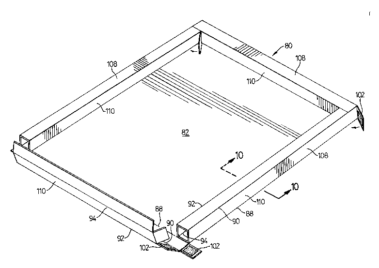
A third embodiment of a pallet top is shown at 80 in Figure 8
partially assembled from the blank in Figure 9. Pallet top 80 comprises a planarcorrugate sheet with a central section 82 and edge portions 84 provided with
creases to give several flaps. When assembled, the blank of Figure 9 is folded
along crease lines 88, 90, 92 and 94 and glued to give reinforced edge
members or runners 108 having a square cross section as shown in Figure 10.
Each elongate runner includes two spaced, parallel flaps 110. Glue patches
100 are used to glue appropriate flaps of the runners to the top portion of
central section 82 and patches 102 are employed to glue flaps on one runner
to the adjacent runners. When assembled pallet top 80 has rectangular tubes
108 extending along each of the edges thereof having two parallel and spaced
sections 110 each perpendicular to central section 82.
The presence of two spaced sections 110 oriented perpendicular
to central section 82 along the peripheral edges of pallet top 80 act to reinforce
the peripheral edges of the pallet top thereby significantly increasing the
resistance of the pallet top to bending and warping.
While the pallet top constructed in accordance with the present
invention has been described and illustrated with respect to the preferred and
alternative embodiments, it will be appreciated by those skilled in the art thatnumerous other embodiments of the pallet top may be made without departing
from the scope of the invention disclosed herein.