Sélection de la langue

Search

Sommaire du brevet 2148627 

Énoncé de désistement de responsabilité concernant l'information provenant de tiers

Une partie des informations de ce site Web a été fournie par des sources externes. Le gouvernement du Canada n'assume aucune responsabilité concernant la précision, l'actualité ou la fiabilité des informations fournies par les sources externes. Les utilisateurs qui désirent employer cette information devraient consulter directement la source des informations. Le contenu fourni par les sources externes n'est pas assujetti aux exigences sur les langues officielles, la protection des renseignements personnels et l'accessibilité.

Disponibilité de l'Abrégé et des Revendications

L'apparition de différences dans le texte et l'image des Revendications et de l'Abrégé dépend du moment auquel le document est publié. Les textes des Revendications et de l'Abrégé sont affichés :

  • lorsque la demande peut être examinée par le public;
  • lorsque le brevet est émis (délivrance).
(12) Brevet: (11) CA 2148627
(54) Titre français: UNITE D'IMPRESSION A PRESSE BLANCHET-BLANCHET
(54) Titre anglais: PRINTING UNIT FOR BLANKET-TO-BLANKET PRINTING
Statut: Périmé et au-delà du délai pour l’annulation
Données bibliographiques
(51) Classification internationale des brevets (CIB):
  • B41F 9/08 (2006.01)
  • B41F 7/12 (2006.01)
  • B41N 10/00 (2006.01)
(72) Inventeurs :
  • WECH, ERICH (Allemagne)
(73) Titulaires :
  • MANROLAND AG
(71) Demandeurs :
  • MANROLAND AG (Allemagne)
(74) Agent: SMART & BIGGAR LP
(74) Co-agent:
(45) Délivré: 1998-12-08
(22) Date de dépôt: 1995-05-04
(41) Mise à la disponibilité du public: 1995-11-05
Requête d'examen: 1995-05-04
Licence disponible: S.O.
Cédé au domaine public: S.O.
(25) Langue des documents déposés: Anglais

Traité de coopération en matière de brevets (PCT): Non

(30) Données de priorité de la demande:
Numéro de la demande Pays / territoire Date
P 44 15 711.8 (Allemagne) 1994-05-04

Abrégés

Abrégé français

Unité d'impression pour presse blanchet contre blanchet. Cette unité est constituée de deux couples d'impression placés l'un par-dessus l'autre. Chaque couple comprend un cylindre gravé et un cylindre de transfert. Les cylindres de transfert sont recouverts chacun d'un blanchet sans trous. Une bande continue horizontale passe entre les cylindres de transfert des deux couples d'impression. Afin d'obtenir une bonne qualité d'impression et un parcours de bande avantageux, un plan reliant les centres des cylindres de transfert est incliné à partir d'un plan s'étendant perpendiculairement à la bande et traversant le centre d'un des cylindres de transfert à un angle (alpha) de 0 à 10 degrés, mais de préférence à un angle de 5 degrés.


Abrégé anglais


The present invention relates to a printing unit for blanket-to-blanket
printing. The printing unit includes two printing couples positioned one on top of the
other. Each printing couple includes a form cylinder and a transfer cylinder. The transfer
cylinders each carry a gap-free blanket. A horizontal web passes between the transfer
cylinders of the two printing couples. In order to achieve good print quality with an
advantageous web path, a plane connecting the centers of the transfer cylinders is inclined
from a plane extending perpendicular to the web and passing through the center of one of
the transfer cylinders by an angle (.alpha.) in the range from 0° to 10° and optimally by an
angle of 5°.

Revendications

Note : Les revendications sont présentées dans la langue officielle dans laquelle elles ont été soumises.


What is claimed:
1. A printing unit for blanket-to-blanket printing on a traveling
substantially horizontal web, the printing unit comprising upper and lower printing couples
each including a transfer cylinder, a gap-free elastomeric blanket positioned around a
respective one of said transfer cylinders, and a form cylinder; the upper printing couple
being positioned above the lower printing couple with the transfer cylinder of the upper
printing couple forming a line of contact with the transfer cylinder of the lower printing
couple, the web passing through the line of contact, a plane connecting the centers of said
two transfer cylinders being inclined relative to the vertical by an angle (.alpha.) of up to
10°.
2. The printing unit as claimed in claim 1, wherein the plane connecting
the centers of the two transfer cylinders is inclined away from the vertical in the direction
of travel of the web.
3. The printing unit as claimed in claim 1, wherein the plane connecting
the centers of the two transfer cylinders is inclined away from the vertical in a direction
opposite the direction of travel of web.
4. The printing unit as claimed in claim 1, further comprising a support
for said blanket, and wherein said blanket is applied to said support as a layer.

5. The printing unit as claimed in claim 1, further comprising a support
for said blanket, and wherein said blanket is glued to said support in a gap-free manner.
6. The printing unit as claimed in claim 1, wherein the transfer cylinder
has a cylinder face side and further comprising means for removing said blanket from the
face side of its respective transfer cylinder without removing said transfer cylinder from
the printing unit.
7. The printing unit as claimed in claim 1, wherein said angle (.alpha.) is
about 5°.

Description

Note : Les descriptions sont présentées dans la langue officielle dans laquelle elles ont été soumises.

2148627
PRINTING UNIT FOR BLANKET-TO-BLANKET PRINTING
BACKGROUND OF THE INVENTION
Field of the Invention
The present invention relates to a printing machine for blanket-to-blanket
printing having a horizontal web path and, more particularly, to a printing unit having
printing couples arranged one above the other with ~la~L~r~r cylinders having gap-free
blankets and whereirl a plane conn~cting the center of each of the llal~rer cylinders of the
printing couples lies at an angle to the vertical.
Description of the Prior Art
A printing unit for blarlket-to-blanket printing having a horizontal web path
is disclosed in German Patent No. DE 27 54 429 C2. In the printing unit described by
this patent, two printing couples, each having a plate cylinder and a transfer cylinder, are
arranged one above the other. The web being printed, which runs horizontally thereto,
is passed between the transfer cylinders. The plane extending between the center of each
of the transfer cylinders is inclined from the vertical by a relatively large angle of
approximately 30. The vertical being a line extending substantially perpendicular to the
web. This measure ensures that the tlal~rer cylinders are contacted by the web at an angle
to the plane extending between the centers of the cylinders. Such an angle is necess~ry
because the transfer cylinders have clamping channels. Given a vertical arrangement of
cylinders of this type, one directly above the other, the pressure on the web would be

`- ~148627
interrupted as the clamping channels pass through the printing zone. The web tension and
web constraint exercised by the printing unit would also be intellupled at this point.
However, positioning the transfer cylinders at an incline of such magnitude as disclosed
in this German Patent provides numerous disadvantages when printing. One such
5 disadvantage is that the rotational speed of the transfer cylinders in the area of angular
contact is greater than the web speed. This causes movement between the web and the
transfer cylinders which has a negative impact on the print quality. Furthermore, the
greater rotational speed of the transfer cylinders results from the larger radius of these
cylinders as compared to the radius of the printing zone.
German Patent No. DE-PS 35 43 704 discloses a printing unit in which the
rubber blanket sleeves are changed while the cylinders remain in the printing unit and are
being suspended on one side.
It is thus desirable to produce a printing unit for blanket-to-blanket printing
which does not intellupt the ~ressule on the web as the clamping channels pass through
15 the printing zone, but wherein the rotational speed of the transfer cylinders is not greater
than the web speed in the area of angular contact. This printing unit should also allow for
ch~nging the rubber blanket sleeves of the l~al~r~r cylinders without removing the
cylinders.

"- 21~8627
SUMMARY OF THE INVENTION
The printing unit of the present invention includes two printing couples.
Each printing couple includes a form cylinder and a transfer cylinder. The printing
couples are positioned one above the other with the transfer cylinders of each couple being
5 in contact with each other. Passing between the transfer cylinders is a horizontal web.
The transfer cylinders are positioned such that a plane connecting the center or axis of
each of the transfer cylinders of the printing couples is inclined by an angle between 0
and 10 from the vertical corresponding to the plumb. This angling of the plane
connecting the centers of the printing couples reduces the angular-contact area of the
10 transfer cylinders. This in turn reduces the movement between the web and the cylinder
surface and thus improves the print quality. Ideally, from this point of view, the angular
contact should be dispensed with entirely. However, in actuality, removing the angular
contact is disadvantageous. If there is no angular contact, the web would always continue
to adhere to the cylinder with the larger printing share of the subject at the moment after
15 leaving the printing gap. The web would thus wobble, depending on the printing share
of the particular subject. This effects the web tension and print quality, i.e., enlargement
of halftone dots, circumferential doubling, circumferential register errors, etc..., in a
negative manner. Optimum angular contact which meets the technical printing
requirements and the requirements for a stable web path is achieved by inclining the
20 transfer cylinders at an angle in the range as specified above.
The various features of novelty which characterize the invention are pointed
out with particularity in the claims annexed to and forming a part of the disclosure. For
a better understanding of the invention, its operating advantages, specific objects att~in~
by its use, reference should be had to the drawing and descriptive matter in which there
25 are illustrated and described preferred embodiments of the invention.

_ - ~148627
BP~IEF DESCRIPTION OF THE DRAWINGS
The drawings show:
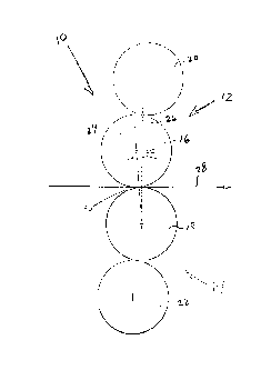
Fig. 1 is a schematic side view of two printing couples aligned one on top
of the other in accordance with the present invention;
Fig. 2 is a cross-sectional view of a transfer cylinder of the present
invention;
Fig. 3 is a cross-sectional view of an alternate embodiment of a transfer
cylinder of the present invention; and
Fig. 4 is a top view of a portion of the printing unit of the present invention
10 having a pivotable bearing on one end thereof.

`- ~148627
DETAILED DESCRIPTION OF THE PREFERRED EMBODIMENT
The present invention will now be described in more detail with reference
to Figure 1.
The printing unit 10 of the present invention is shown schematically in side
5 view in Fig. 1. The printing unit 10 includes first and second printing couples 12, 14.
Each printing couple 12, 14 respectively includes a transfer cylinder 16, 18 and a form
cylinder 20, 22. The transfer cylinders 16, 18 are arranged one above the other. The
transfer cylinders 16, 18 work together and form a line of contact with one another. As
used, the term "line of contact" is intended to include a line or a relatively narrow band
10 of contact resulting from the yielding of the transfer cylinders 16, 18 due to their
engagement. A web 28 passes between the transfer cylinders 16, 18. A plane 24
extending between the center or axis of each of the transfer cylinders 16, 18 is at an angle
o~ to the vertical 26 substantially perpendicular to the web 28 and passing through the
center of one of the cylinders 16 or 18. The contact point 30 between the transfer
15 cylinders 16, 18 is therefore displaced from the vertical 26 in a direction opposite to the
direction of travel of the web 28 between the transfer cylinders 16, 18.
Specifically, the plane 24 extending through the center of each of the
transfer cylinders 16, 18 is preferably inclined from the vertical 26 by an angle ~ of about
5. However, the angle c~ may be selected at any angle in a range of from 0 to 10.
20 The angle ~ may lie on either side of the vertical 26. In other words, the plane 24
connPcting the center of each of the transfer cylinders 16, 18 may be inclined in the
direction of travel of the web 28 or inclined against the direction of travel of the web 28.
Fig. 1 shows an angle ~ and the plane 24 conn~cting the centers of the transfer cylinders
lying on a side of the vertical 26 against the direction of travel of the web. The side of
25 the vertical 26 on which the angle ~ lies depends upon whether the vertical 26 passes
through the center of transfer cylinder 16 or transfer cylinder 18.
The transfer cylinders 16, 18 may both be equipped with a continuous
elastomeric blanket 34 as shown in Fig. 2. Blanket 34 can be made of rubber, synthetic
rubber, ethylene propylene copolymer or any other suitable elastomeric or yieldable
30 material. This figure shows a cross-section of a transfer cylinder 16. The blanket 34 can

2148627
be applied as a layer to a support 32 designed as a sleeve. The blanket 34 may also be
applied in a gap-free manner on the transfer cylinder 16. The support 32 may also have
a plate-type design.
A variation on this transfer cylinder 16 is shown in Fig. 3. Here the
5 transfer cylinder 16 has a slot 36. The slot 36 extends in the axial direction and into
which bevelled legs 38, 40 of a plate-type support 42 are inserted. A blanket 44 made of
elastomeric material like blanket 34 is positioned over the support 42 in a gap-free
manner.
The present invention may also be designed such that the elastomeric or
10 yieldable blanket sleeve 46, a fragment of which is shown in Fig. 4, may be changed on
the cylinder-face side without removing the cylinder 16. This figure illustrates a portion
of the printing unit 10. In the side wall 48 of the printing unit 10 there is a pivotable
bearing 52 which is able to pivot about a hinge 54. The other end of the cylinder 16 is
attached to the opposing side wall 56 using a stationary bearing 58. When it is desired to
15 change the blanlcet sleeve 46, the pivotable bearing 52 is pivoted away, thus diseng~gin~
it, from the side wall 48. This provides an opening 50 for ch~nging the sleeve 46. The
cylinder 16 is held in suspension during the ch~nging of the sleeve by the bearing 58 in
the opposing side wall 56.
In operation, the two printing couples are arranged one on top of the other
20 such that the transfer cylinders of the printing couples are in contact with one another.
Passing between the transfer cylinders is a material on which an image is desired to be
printed. As the material passes between the transfer cylinders, it contacts both the transfer
cylinders allowing an image to be printed on both sides of the material. The path of the
material is along a substantially horizontal plane with respect to the printing couples. The
25 transfer cylinders are positioned so as to be inclined by an angle between 0 and 10 from
the vertical. The inclining of the transfer cylinders in this manner produces certain
improvements which are not found in prior printing units. Such improvements include a
reduction in movement between the web and the cylinder surface and preventing adherence
of the web to the printing surface having a larger printing share of the subject at the
30 moment after leaving the printing gap.

~ 21~8627
The invention is not limited by the embodiments described above which are
presented as examples only but can be modified in various ways within the scope of
protection defined by the appended patent claims.

Dessin représentatif
Une figure unique qui représente un dessin illustrant l'invention.
États administratifs

2024-08-01 : Dans le cadre de la transition vers les Brevets de nouvelle génération (BNG), la base de données sur les brevets canadiens (BDBC) contient désormais un Historique d'événement plus détaillé, qui reproduit le Journal des événements de notre nouvelle solution interne.

Veuillez noter que les événements débutant par « Inactive : » se réfèrent à des événements qui ne sont plus utilisés dans notre nouvelle solution interne.

Pour une meilleure compréhension de l'état de la demande ou brevet qui figure sur cette page, la rubrique Mise en garde , et les descriptions de Brevet , Historique d'événement , Taxes périodiques et Historique des paiements devraient être consultées.

Historique d'événement

Description Date
Le délai pour l'annulation est expiré 2014-05-06
Lettre envoyée 2013-05-06
Inactive : TME en retard traitée 2012-07-05
Lettre envoyée 2012-05-04
Lettre envoyée 2008-10-28
Inactive : CIB de MCD 2006-03-11
Accordé par délivrance 1998-12-08
Inactive : Taxe finale reçue 1998-05-29
Préoctroi 1998-05-29
Lettre envoyée 1998-04-16
Un avis d'acceptation est envoyé 1998-04-16
Inactive : Renseign. sur l'état - Complets dès date d'ent. journ. 1998-04-08
Inactive : Dem. traitée sur TS dès date d'ent. journal 1998-04-08
Inactive : Approuvée aux fins d'acceptation (AFA) 1998-03-11
Inactive : Demande ad hoc documentée 1997-05-05
Réputée abandonnée - omission de répondre à un avis sur les taxes pour le maintien en état 1997-05-05
Demande publiée (accessible au public) 1995-11-05
Exigences pour une requête d'examen - jugée conforme 1995-05-04
Toutes les exigences pour l'examen - jugée conforme 1995-05-04

Historique d'abandonnement

Date d'abandonnement Raison Date de rétablissement
1997-05-05

Taxes périodiques

Le dernier paiement a été reçu le 1998-05-04

Avis : Si le paiement en totalité n'a pas été reçu au plus tard à la date indiquée, une taxe supplémentaire peut être imposée, soit une des taxes suivantes :

  • taxe de rétablissement ;
  • taxe pour paiement en souffrance ; ou
  • taxe additionnelle pour le renversement d'une péremption réputée.

Veuillez vous référer à la page web des taxes sur les brevets de l'OPIC pour voir tous les montants actuels des taxes.

Titulaires au dossier

Les titulaires actuels et antérieures au dossier sont affichés en ordre alphabétique.

Titulaires actuels au dossier
MANROLAND AG
Titulaires antérieures au dossier
ERICH WECH
Les propriétaires antérieurs qui ne figurent pas dans la liste des « Propriétaires au dossier » apparaîtront dans d'autres documents au dossier.
Documents

Pour visionner les fichiers sélectionnés, entrer le code reCAPTCHA :


Pour visualiser une image, cliquer sur un lien dans la colonne description du document. Pour télécharger l'image (les images), cliquer l'une ou plusieurs cases à cocher dans la première colonne et ensuite cliquer sur le bouton "Télécharger sélection en format PDF (archive Zip)" ou le bouton "Télécharger sélection (en un fichier PDF fusionné)".

Liste des documents de brevet publiés et non publiés sur la BDBC .

Si vous avez des difficultés à accéder au contenu, veuillez communiquer avec le Centre de services à la clientèle au 1-866-997-1936, ou envoyer un courriel au Centre de service à la clientèle de l'OPIC.


Description du
Document 
Date
(aaaa-mm-jj) 
Nombre de pages   Taille de l'image (Ko) 
Page couverture 1998-12-07 1 43
Description 1995-11-05 7 254
Page couverture 1996-07-02 1 18
Abrégé 1995-11-05 1 19
Dessins 1995-11-05 3 48
Revendications 1995-11-05 2 44
Dessin représentatif 1998-12-07 1 4
Avis du commissaire - Demande jugée acceptable 1998-04-16 1 164
Avis concernant la taxe de maintien 2012-06-15 1 172
Quittance d'un paiement en retard 2012-07-05 1 164
Avis concernant la taxe de maintien 2013-06-17 1 170
Taxes 1998-05-04 1 45
Correspondance 1998-05-29 1 45
Taxes 1999-05-03 1 42
Taxes 1997-05-01 1 47
Correspondance de la poursuite 1995-05-04 2 52