Sélection de la langue

Search

Sommaire du brevet 2148721 

Énoncé de désistement de responsabilité concernant l'information provenant de tiers

Une partie des informations de ce site Web a été fournie par des sources externes. Le gouvernement du Canada n'assume aucune responsabilité concernant la précision, l'actualité ou la fiabilité des informations fournies par les sources externes. Les utilisateurs qui désirent employer cette information devraient consulter directement la source des informations. Le contenu fourni par les sources externes n'est pas assujetti aux exigences sur les langues officielles, la protection des renseignements personnels et l'accessibilité.

Disponibilité de l'Abrégé et des Revendications

L'apparition de différences dans le texte et l'image des Revendications et de l'Abrégé dépend du moment auquel le document est publié. Les textes des Revendications et de l'Abrégé sont affichés :

  • lorsque la demande peut être examinée par le public;
  • lorsque le brevet est émis (délivrance).
(12) Brevet: (11) CA 2148721
(54) Titre français: STAND A ELEMENT VERTICAL
(54) Titre anglais: VERTICAL MEMBER SUPPORT STAND
Statut: Périmé et au-delà du délai pour l’annulation
Données bibliographiques
(51) Classification internationale des brevets (CIB):
  • F16M 11/32 (2006.01)
  • A47G 33/12 (2006.01)
  • F16M 11/20 (2006.01)
(72) Inventeurs :
  • ROBERT, JACQUES (Canada)
(73) Titulaires :
  • JACQUES ROBERT
(71) Demandeurs :
(74) Agent:
(74) Co-agent:
(45) Délivré: 2000-04-04
(22) Date de dépôt: 1995-04-27
(41) Mise à la disponibilité du public: 1995-11-03
Requête d'examen: 1998-04-23
Licence disponible: S.O.
Cédé au domaine public: S.O.
(25) Langue des documents déposés: Anglais

Traité de coopération en matière de brevets (PCT): Non

(30) Données de priorité de la demande:
Numéro de la demande Pays / territoire Date
08/235,888 (Etats-Unis d'Amérique) 1994-05-02

Abrégés

Abrégé anglais


A vertical member support stand is described which
includes a body with a generally tubular vertical member
receiving cavity. The cavity has a bottom, a top opening, and
circumferential sidewalls. At least three upper pressure
members are substantially equally spaced around the
circumferential sidewalls of the vertical member receiving
cavity adjacent the top opening. The pressure members are
pivotally mounted whereby they are pivoted into engagement
with a vertical member positioned in the vertical member
receiving cavity. At least three lower pressure members are
substantially equally spaced around the circumferential
sidewalls of the vertical member receiving cavity adjacent the
bottom. The pressure members are pivotally mounted whereby
they are pivoted into engagement with a vertical member
positioned in the vertical member receiving cavity. The
pressure members are locked in a selected pivotal position
such that they securely hold the vertical member.

Revendications

Note : Les revendications sont présentées dans la langue officielle dans laquelle elles ont été soumises.


THE EMBODIMENTS OF THE INVENTION IN WHICH AN EXCLUSIVE
PROPERTY OR PRIVILEGE IS CLAIMED ARE AS FOLLOWS:
1. A vertical member support stand, comprising:
a. a body with a generally tubular vertical member
receiving cavity, the cavity having a bottom, a top opening,
and circumferential sidewalls;
b. at least three upper pressure members substantially
equally spaced around the circumferential sidewalls of the
vertical member receiving cavity adjacent the top opening, the
pressure members being pivotally mounted whereby they are
pivoted into engagement with a vertical member positioned in
the vertical member receiving cavity;
c. at least three lower pressure members substantially
equally spaced around the circumferential sidewalls of the
vertical member receiving cavity adjacent the bottom, the
pressure members being pivotally mounted whereby they are
pivoted into engagement with a vertical member positioned in
the vertical member receiving cavity, each of the pressure
members has a mounting end and a vertical member engaging end,
the mounting end having a gear segment along its peripheral
edge and a transverse mounting aperture; and
d. means for locking the pressure members in a selected
pivotal position, including a gear engaging locking member
movable between an engaged and a disengaged position, in the
engaged position the locking member engages the gear segment
at the mounting end of the pressure member, in the disengaged
position the locking member is spaced from the pressure
member.
2. The vertical member support stand as defined in Claim 1,
wherein an upstanding spike is secured to the bottom of the
vertical member receiving cavity in a substantially central
position relative to the circumferential sidewalls.
3. The vertical member support stand as defined in Claim 1,
wherein the body has feet projecting radially outwardly away
from the body.

4. The vertical member support stand as defined in Claim 1,
wherein the locking member is a pivotally mounted member with
a projecting engagement tooth.
5. The vertical member support stand as defined in Claim 1,
wherein the mounting end of each of the pressure members is
receiving in a pocket in the circumferential sidewall of the
vertical member receiving cavity.

6. A vertical member support stand, comprising:
a. a body with an exterior surface, a generally tubular
vertical member receiving cavity and stabilizing feet
projecting radially outwardly from the exterior surface away
from the body, the cavity having a bottom, a top opening, an
axis extending between the bottom and the top opening and
circumferential sidewalls, the circumferential sidewalls
having generally arcuate channel-form pockets which are
parallel to the cavity axis and have a slot which communicates
with the exterior surface;
b. an upstanding spike secured to the bottom of the
vertical member receiving cavity in a substantially central
position relative to the circumferential sidewalls;
c. at least three upper pressure members substantially
equally spaced around the circumferential sidewalls of the
vertical member receiving cavity adjacent the top opening,
each of the pressure members having a mounting end and a
vertical member engaging end, the mounting end having a gear
segment along its peripheral edge and a transverse mounting
aperture, the mounting end of each of the pressure members is
received in one of the pockets in the circumferential sidewall
of the vertical member receiving cavity with a pivot pin
extending through the mounting aperture such that the pressure
member pivots into engagement with a vertical member
positioned in the vertical member receiving cavity;
d. at least three lower pressure members substantially
equally spaced around the circumferential sidewalls of the
vertical member receiving cavity adjacent the bottom, each of
the pressure members having a mounting end and a vertical
member engaging end, the mounting end having a gear segment
along its peripheral edge and a transverse mounting aperture,
the mounting end of each of the pressure members is received
in one of the pockets in the circumferential sidewall of the
vertical member receiving cavity with a pivot pin extending
through the mounting aperture such that the pressure member
pivots into engagement with a vertical member positioned in

the vertical member receiving cavity; and
e. locking members with at least one projecting
engagement tooth pivotally mounted to the exterior of the
body, the locking members being pivotally movable between an
engaged and a disengaged position, in the disengaged position
the locking member is spaced from the pressure member, in the
engaged position the at least one engagement tooth of the
locking member projects through the slot to engage the gear
segment at the mounting end of the pressure member thereby
locking the pressure members in a selected pivotal position.
7. A vertical member support stand, comprising:
a. a body with a generally tubular vertical member
receiving cavity, the cavity having a bottom, a top opening,
and circumferential sidewalls, the circumferential sidewalls
having a plurality of pockets;
b. at least three upper pressure members substantially
equally spaced around the circumferential sidewalls of the
vertical member receiving cavity adjacent the top opening, the
pressure members being pivotally mounted whereby they are
pivoted into engagement with a vertical member positioned in
the vertical member receiving cavity;
c. at least three lower pressure members substantially
equally spaced around the circumferential sidewalls of the
vertical member receiving cavity adjacent the bottom, the
pressure members being pivotally mounted whereby they are
pivoted into engagement with a vertical member positioned in
the vertical member receiving cavity, each of the pressure
members having a mounting end that is received one of the
pockets in the circumferential sidewall of the vertical member
receiving cavity; and
d. means for locking the pressure members in a selected
pivotal position.

Description

Note : Les descriptions sont présentées dans la langue officielle dans laquelle elles ont été soumises.

2148721
The present invention relates to a vertical member
support stanu
BACRGROUN-D OF THE lNV~N'l'ION
There are a variety of objects that are supported in an
upright position during use. In order to support them in an
upright position a support stand is used. The objects being
supported can take the form of a variety of vertical members.
Some examples of such vertical members are poles or st~n~rds
bearing banners, flags, signs, etc. The number of potential
applications for such vertical member support stands is almost
infinite.
Most vertical member support stands can effectively hold
and support a vertical member that is substantially
symmetrical. When the vertical member is not symmetrical,
however, there is a danger that one of the pressure members
will release it's grip resulting in a rapid and violent
falling of the vertical member.
The most common example of a vertical member support
stand that must support an asymmetrical member is a tree
stand. The tree stand is used to support a tree in an upright
position after its root system has been severed. The most
common use of a tree stand is to support Christmas Trees
during the Christian celebration of the birth of Jesus Christ.
The trunks of trees are not perfectly cylindrical, they are
therefore very difficult to firmly grasp. Furthermore, the
branches of the tree do not extend radially in a perfectly
symmetrical fashion. This results in an uneven weight
distribution leading to a marked tendency for the tree to lean
in a particular direction.
SUMMARY OF THE lNv~Nl~lON
What is required is a vertical member support stand that

2148721
is better at holding asymmetrical members.
According to the present invention there is provided a
vertical member support stand which includes a body with a
generally tubular vertical member receiving cavity. The
cavity has a bottom, a top opening, and circumferential
sidewalls. At least three upper pressure members are
substantially equally spaced around the circumferential
sidewalls of the vertical member receiving cavity adjacent the
top opening. The pressure members are pivotally mounted
whereby they are pivoted into engagement with a vertical
member positioned in the vertical member receiving cavity. At
least three lower pressure members are substantially equally
spaced around the circumferential sidewalls of the vertical
member receiving cavity adjacent the bottom. The pressure
members are pivotally mounted whereby they are pivoted into
engagement with a vertical member positioned in the vertical
member receiving cavity. Means are provided for locking the
pressure members in a selected pivotal position.
With the vertical member support stand, as described
above, there are a minimum of six pressure members, all of
which individually can be brought into engagement with a trunk
of a vertical member positioned in the vertical member
receiving cavity. It is preferred that an upstanding spike is
secured to the bottom of the vertical member receiving cavity
in a substantially central position relative to the
circumferential sidewalls. The presence of the spike prevents
a lateral sliding movement of the vertical member along the
bottom of the vertical member receiving cavity.
There are a number of ways of locking the pressure
members in a selected pivotal position. It is preferred that
each of the pressure members has a mounting end and a vertical
member engaging end. The mounting end has a gear segment
along its peripheral edge and a transverse mounting aperture.

2148721
The means for locking the pressure members in a selected
pivotal position includes a gear engaging locking member
movable between an engaged and a disengaged position. In the
engaged position the locking member engages the gear segment
at the mounting end of the pressure member. In the disengaged
position the locking member is spaced from the pressure
member. It is preferred that the locking member is a
pivotally mounted member with at least one projecting
engagement tooth.
BRIEF DESCRIPTION OF THE DRAWINGS
These and other features of the invention will become
more apparent from the following description in which
reference is made to the appended drawings, wherein:
FIGURE 1 is a perspective view of a vertical member
support stand constructed in accordance with the teachings of
the present invention.
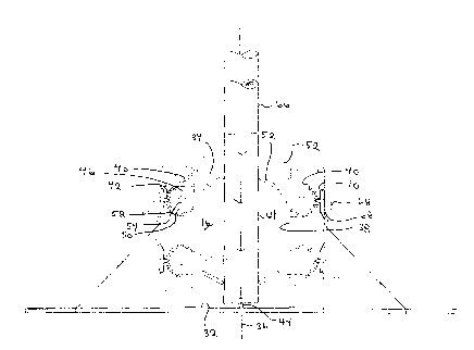
20FIGURE 2 is a side elevation view in longitudinal section
of the vertical member support stand illustrated in FIGURE 1.
FIGURE 3 is a an exploded perspective view of a portion
of the vertical member support stand illustrated in FIGURE 1.
DETAILED DESCRIPTION OF THE ~ KRED EMBODIMENT
The preferred embodiment, a vertical member support stand
generally identified by reference numeral 10, will now be
described with reference to FIGURES 1 through 3.
Referring to FIGURE 1, vertical member support stand 10
consists of a body 12 with an exterior surface 14, a generally
tubular vertical member receiving cavity 16 and stabilizing
feet 18 projecting radially outwardly from exterior surface 14
away from body 12. Strengthening gusset members 20 are
secured between exterior surface 14 and stabilizing feet 18.

2148721
Referring to FIGURE 3, is can be seen that for ease of
fabrication and assembly body 12 is made in several pieces.
The primary piece is a shell 22 having insert receiving
channels 24 which have interior dove-tail grooves 26.
Parallelepiped inserts 28 fit into insert receiving channels
24. Inserts 28 have dove-tail tongues 30 which mate with
dove-tail grooves 26. Referring to FIGURE 2, cavity 16 has a
bottom 32, a top opening 34, an axis 36 extending between
bottom 32 and top opening 34 and circumferential sidewalls 38.
Circumferential sidewalls 38 having generally arcuate channel-
form pockets 40 which are parallel to axis 36 and have a slot
42 which communicates with exterior surface 14. An upstanding
spike 44 is secured to bottom 32 of vertical member receiving
cavity 16 in a substantially central position relative to
circumferential sidewalls 38, ie. substantially co-axial with
axis 36. Referring to FIGURE 1, four upper presgure members
46 are substantially equally spaced around circumferential
sidewalls 38 of vertical member receiving cavity 16 adjacent
to top opening 34. Although they are not all fully visible
from the views provided there are also four lower presgure
members 48 which are substantially equally spaced around
circumferential sidewalls 38 of vertical member receiving
cavity 16 adjacent to bottom 32. Referring to FIGURE 3, each
of presgure members 46 and 48 having a mounting end 50 and a
vertical member engaging end 52. Mounting end 50 has a gear
segment 54 along its peripheral edge 56 and a transverse
mounting aperture 58. Vertical member engaging end 52 has
projecting teeth 60. Referring to FIGURE 2, mounting end 50
of each of pressure members 46 and 48 is received in one of
pockets 40 in circumferential sidewall 38 of vertical member
receiving cavity 16. A pivot pin 62 extends through mounting
aperture 58 to pivotally mount presgure members 46 and 48. As
is apparent from a review of FIGURE 2, pressure members 46 and
48 pivot into engagement with a vertical member 64 which in
this case is the trunk of a tree 66 positioned in vertical
member receiving cavity 16. Locking members 68 are pivotally
mounted to exterior surface 14 of body 12. Each of locking

2148721
members 68 has a projecting engagement tooth 70. Locking
members 68 are pivotally movable between an engaged and a
disengaged position. The disengaged position is shown in
ghost lines on FIGURE 2. In this disengaged position locking
member 68 is spaced from pressure member 46 and 48. The
engaged position is shown in FIGURE 2. In this engaged
position engagement tooth 70 of locking member 68 projects
through slot 42 to engage gear segment 54 at mounting end 50
of pressure members 46 or 48. This locks pressure members 46
and 48 in a selected pivotal position.
The use and operation of vertical member support stand 10
will now be described with reference to FIGURES 1 through 3.
Vertical member 64 is inserted into vertical member receiving
cavity 16 in the manner illustrated in FIGURE 2 until vertical
member 64 is impaled upon upstAn~ing spike 44. As vertical
member 64 approaches bottom 32 of vertical member receiving
cavity 16, the four lower pressure members 48 are pushed
downwardly. Lower pressure members are locked in position by
pivoting locking member 68 to bring engagement tooth 70 into
engagement with gear segment 54. The four upper pressure
members 46 are then pivoted into engagement with vertical
member 64 and locked in position with locking members 68 in a
like fashion.
It will be apparent to one skilled in the art that having
four independent pressure members enables vertical member
support stand 10 to more readily adapt to irregular shaped
vertical member trunks. It will also be apparent to one
skilled in the art that modifications may be made to the
illustrated embodiment without departing from the spirit and
scope of the invention as defined by the Claims. In
particular, the number of pressure members 46 and 48 can be
reduced to three of each or increased to more than four. Four
is preferred merely because it provides the balanced support
that is desired.

Dessin représentatif
Une figure unique qui représente un dessin illustrant l'invention.
États administratifs

2024-08-01 : Dans le cadre de la transition vers les Brevets de nouvelle génération (BNG), la base de données sur les brevets canadiens (BDBC) contient désormais un Historique d'événement plus détaillé, qui reproduit le Journal des événements de notre nouvelle solution interne.

Veuillez noter que les événements débutant par « Inactive : » se réfèrent à des événements qui ne sont plus utilisés dans notre nouvelle solution interne.

Pour une meilleure compréhension de l'état de la demande ou brevet qui figure sur cette page, la rubrique Mise en garde , et les descriptions de Brevet , Historique d'événement , Taxes périodiques et Historique des paiements devraient être consultées.

Historique d'événement

Description Date
Inactive : CIB de MCD 2006-03-11
Le délai pour l'annulation est expiré 2003-04-28
Inactive : Demande ad hoc documentée 2003-01-29
Lettre envoyée 2002-04-29
Accordé par délivrance 2000-04-04
Inactive : Page couverture publiée 2000-04-03
Préoctroi 2000-01-10
Inactive : Taxe finale reçue 2000-01-10
Un avis d'acceptation est envoyé 1999-07-09
Lettre envoyée 1999-07-09
Inactive : Approuvée aux fins d'acceptation (AFA) 1999-06-25
Lettre envoyée 1998-07-23
Inactive : Renseign. sur l'état - Complets dès date d'ent. journ. 1998-07-23
Inactive : Dem. traitée sur TS dès date d'ent. journal 1998-07-23
Inactive : Lettre officielle 1998-05-01
Exigences pour une requête d'examen - jugée conforme 1998-04-23
Toutes les exigences pour l'examen - jugée conforme 1998-04-23
Inactive : Demande ad hoc documentée 1997-04-28
Réputée abandonnée - omission de répondre à un avis sur les taxes pour le maintien en état 1997-04-28
Demande publiée (accessible au public) 1995-11-03

Historique d'abandonnement

Date d'abandonnement Raison Date de rétablissement
1997-04-28

Taxes périodiques

Le dernier paiement a été reçu le 1999-04-21

Avis : Si le paiement en totalité n'a pas été reçu au plus tard à la date indiquée, une taxe supplémentaire peut être imposée, soit une des taxes suivantes :

  • taxe de rétablissement ;
  • taxe pour paiement en souffrance ; ou
  • taxe additionnelle pour le renversement d'une péremption réputée.

Veuillez vous référer à la page web des taxes sur les brevets de l'OPIC pour voir tous les montants actuels des taxes.

Historique des taxes

Type de taxes Anniversaire Échéance Date payée
Requête d'examen - petite 1998-04-23
TM (demande, 3e anniv.) - petite 03 1998-04-27 1998-04-23
TM (demande, 4e anniv.) - petite 04 1999-04-27 1999-04-21
Taxe finale - petite 2000-01-10
TM (brevet, 5e anniv.) - petite 2000-04-27 2000-04-27
TM (brevet, 6e anniv.) - petite 2001-04-27 2001-04-23
Titulaires au dossier

Les titulaires actuels et antérieures au dossier sont affichés en ordre alphabétique.

Titulaires actuels au dossier
JACQUES ROBERT
Titulaires antérieures au dossier
S.O.
Les propriétaires antérieurs qui ne figurent pas dans la liste des « Propriétaires au dossier » apparaîtront dans d'autres documents au dossier.
Documents

Pour visionner les fichiers sélectionnés, entrer le code reCAPTCHA :


Pour visualiser une image, cliquer sur un lien dans la colonne description du document. Pour télécharger l'image (les images), cliquer l'une ou plusieurs cases à cocher dans la première colonne et ensuite cliquer sur le bouton "Télécharger sélection en format PDF (archive Zip)" ou le bouton "Télécharger sélection (en un fichier PDF fusionné)".

Liste des documents de brevet publiés et non publiés sur la BDBC .

Si vous avez des difficultés à accéder au contenu, veuillez communiquer avec le Centre de services à la clientèle au 1-866-997-1936, ou envoyer un courriel au Centre de service à la clientèle de l'OPIC.


Description du
Document 
Date
(aaaa-mm-jj) 
Nombre de pages   Taille de l'image (Ko) 
Page couverture 1996-02-14 1 16
Description 1995-11-03 5 260
Abrégé 1995-11-03 1 29
Revendications 1995-11-03 4 172
Dessin représentatif 2000-02-04 1 10
Dessins 1995-11-03 3 72
Page couverture 2000-02-04 1 40
Accusé de réception de la requête d'examen 1998-07-23 1 194
Avis de rappel: Taxes de maintien 1999-01-28 1 118
Avis du commissaire - Demande jugée acceptable 1999-07-09 1 165
Avis de rappel: Taxes de maintien 2000-01-31 1 121
Avis de rappel: Taxes de maintien 2001-01-30 1 120
Avis de rappel: Taxes de maintien 2002-01-29 1 119
Avis concernant la taxe de maintien 2002-05-27 1 179
Deuxième avis de rappel: taxes de maintien 2002-10-29 1 117
Avis de rappel: Taxes de maintien 2003-01-28 1 115
Correspondance 1998-05-01 1 6
Correspondance 1998-05-01 1 5
Correspondance 1998-04-07 3 66
Correspondance 2000-01-10 1 102
Taxes 2000-04-27 1 106
Taxes 2001-04-23 1 77
Taxes 1998-04-23 1 39
Taxes 1999-04-21 2 119
Taxes 1997-04-25 1 42