Sélection de la langue

Search

Sommaire du brevet 2149424 

Énoncé de désistement de responsabilité concernant l'information provenant de tiers

Une partie des informations de ce site Web a été fournie par des sources externes. Le gouvernement du Canada n'assume aucune responsabilité concernant la précision, l'actualité ou la fiabilité des informations fournies par les sources externes. Les utilisateurs qui désirent employer cette information devraient consulter directement la source des informations. Le contenu fourni par les sources externes n'est pas assujetti aux exigences sur les langues officielles, la protection des renseignements personnels et l'accessibilité.

Disponibilité de l'Abrégé et des Revendications

L'apparition de différences dans le texte et l'image des Revendications et de l'Abrégé dépend du moment auquel le document est publié. Les textes des Revendications et de l'Abrégé sont affichés :

  • lorsque la demande peut être examinée par le public;
  • lorsque le brevet est émis (délivrance).
(12) Demande de brevet: (11) CA 2149424
(54) Titre français: INSTALLATION DE COULEE SEMI-CONTINUE POUR LA FABRICATION DE LINGOTS A LAMINER
(54) Titre anglais: SEMI-CONTINUOUS CASTING EQUIPMENT FOR THE MANUFACTURE OF ROLL INGOTS
Statut: Réputée abandonnée et au-delà du délai pour le rétablissement - en attente de la réponse à l’avis de communication rejetée
Données bibliographiques
(51) Classification internationale des brevets (CIB):
  • B22D 11/08 (2006.01)
  • B22D 29/04 (2006.01)
(72) Inventeurs :
  • STEEN, IDAR (Norvège)
  • NæSS, HARALD JR. (Norvège)
(73) Titulaires :
  • NORSK HYDRO A.S.
(71) Demandeurs :
  • NORSK HYDRO A.S. (Norvège)
(74) Agent: SMART & BIGGAR LP
(74) Co-agent:
(45) Délivré:
(86) Date de dépôt PCT: 1994-09-12
(87) Mise à la disponibilité du public: 1995-04-20
Licence disponible: S.O.
Cédé au domaine public: S.O.
(25) Langue des documents déposés: Anglais

Traité de coopération en matière de brevets (PCT): Oui
(86) Numéro de la demande PCT: PCT/NO1994/000150
(87) Numéro de publication internationale PCT: NO1994000150
(85) Entrée nationale: 1995-05-15

(30) Données de priorité de la demande:
Numéro de la demande Pays / territoire Date
933684 (Norvège) 1993-10-13

Abrégés

Abrégé français

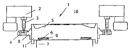
Installation de coulée semi-continue et directe en coquille pour la fabrication de lingots à laminer. L'installation comporte un réservoir supérieur (10) pour métal, une matrice de coulée ou matrice (2) montée sous le réservoir et dotée d'un orifice d'entrée et d'un orifice de sortie, et un fond (7) mobile verticalement prévu au niveau de l'orifice de sortie et muni d'un sabot de coulée (5) adapté pour venir s'appuper contre l'orifice de sortie au début du cycle de coulée. Le sabot de coulée est monté mobile (en 6) sur le fond (7) et conçu pour être solidaire de celui-ci une fois qu'il se trouve en position centrée par rapport à la matrice de coulée (2). En outre, des dispositifs de centrage correspondants (3, 4, 8) destinés respectivement à la matrice de coulée et au sabot de coulée sont prévus pour centrer le sabot de coulée par rapport à la matrice de coulée.


Abrégé anglais


Direct chill, semi-continuous casting equipment for the manufacture of roll
ingots. The equipment comprises an upper metal reservoir (10), a casting die
or die (2) fitted below the metal reservoir with an inlet and an outlet and a
vertically moveable base (7) fitted at the outlet with a casting shoe (5)
which is designed to bear against the outlet at the start of a casting cycle.
The casting shoe is mounted as a moveable shoe (at 6) on the base (7) and is
designed to be locked in relation to the base when it has been brought into a
centred position in relation to the casting die (2). Furthermore,
corresponding centring devices (3, 4, 8) for the casting die and the casting
shoe respectively are fitted for centring the casting shoe in relation to the
casting die.

Revendications

Note : Les revendications sont présentées dans la langue officielle dans laquelle elles ont été soumises.


WO 95/10376 PCT/NO94/00150
Claims
1. Direct chill, semi-continuous casting equipment for the
manufacture of roll ingots consisting of an upper metal
reservoir (10), a casting die fitted below the metal
reservoir (2) with an inlet and an outlet, and a vertically
moveable base (7) fitted to the outlet with a casting shoe
(5) which is designed to bear against the outlet at the
start of a casting cycle,
c h a r a c t e r i z e d i n
that the casting shoe is mounted as a moveable shoe (at 6)
on the base (7) and is designed to be locked in relation to
the base when it has been brought into a centred position
in relation to the casting die (2), whereas for the
centring of the casting shoe in relation to the casting die
corresponding centring devices (3, 4, 8) are fitted for the
casting die and the casting shoe respectively.
2. Casting equipment in accordance with claim 1,
c h a r a c t e r i z e d i n
that the support between the base and the casting shoe
consists of one or more air cushions (6), whereas the base
and the shoe are interlocked by the air supply to the
cushions, being shut off so that the casting shoe is lowered
and rests directly on the base after the casting shoe has
been placed in the correct position in relation to the
casting die.
3. Casting equipment in accordance with claim 1,
c h a r a c t e r i z e d i n
that the cushions are fitted in recesses (9) in the base
(7) or the casting shoe (15).

WO 95/10376 PCT/NO94/00150
4. Casting equipment in accordance with claim 1,
c h a r a c t e r i z e d i n
that the support between the base and the casting shoe
consists of a ball support which can be raised mechanically
in order to lift the casting shoe from the base during the
centring operation.
5. Casting equipment in accordance with claim 1,
c h a r a c t e r i z e d i n
that the centring devices consist of at least two guide
pins (3) fitted on the casting shoe with conically shaped
parts which correspond to two guide sleeves (4) with
conical parts fitted on the casting die or vice versa.
6. Casting equipment in accordance with claim 4,
c h a r a c t e r i z e d i n
that the guide sleeves (4) are fitted in brackets or juts
(8) which are adjustable in relation to the casting shoe or
the casting die.
7. Casting equipment in accordance with claims 1-5,
c h a r a c t e r i z e d i n
that the casting shoe is fitted with a downward projecting
edge (11) which projects outwards and down past the upper
part of the base (7).

Description

Note : Les descriptions sont présentées dans la langue officielle dans laquelle elles ont été soumises.


WO95/10376 2149421 P~T~094100150
Semi-co~tinuous casting equipme~ for the manufacture of
roll in~ots
The present invention concerns direct chill, semi-continuous
casting equipment for the manufacture of roll ingots in metal,
primarily aluminium, comprising an upper metal reservoir, a
casting die with an inlet and an outlet fitted below the metal
reservoir, and a moveable base fitted to the outlet with a
casting shoe which is designed to bear against the outlet at the
start of a casting cycle.
In connection with the manufacture of metal castings of small
dimensions, for example ingots for extrusion purposes, a self-
centring casting shoes is used which is based on a simple
principle in which the casting shoes rest on well-greased bases.
The casting dies or chills are fitted with a guide edge which
guides each of the casting shoes into place in the chill when the
movea~le base is moved up. Because of the small dimensions and
low weight of the casting shoes, this system ~unctions very
satisfactorily.
In connection with roll-ingot casting, however, a similar system
will not function as the casting shoe (just one) for this type of
casting equipment has a considerably larger bearing surface and
is considerably heavler.
In connection with roll-ingot casting it is common to use manual
centri~g of ~the casting shoe by means of a bar. This results in
damage to both the casting shoe and the casting dIe as a
consequence of the barr and because the edge of the shoe touches
the die wall. This damage in the shape of scratches and cu~s on
the die wall and casting shoe respectively can, in turn, result
in sur~ace defects in the roll-ingot workpieces and, in the worst
`: ~

WO95/10376 21~ 9 4 2 1 PCT~094/00150
..
;` 2
:"
~; case, in leakage between the casting die and the casting shoe and
in damaged workpieces.
. , .
Recently, a solution has been introduced on the market in which
the casting shoe i9 stationary, but in which the casting die
~ itself is centred around the shoe. The casting die is thus
ii mounted as a moveable die and designed to be moved by means of
eight pneumatic cylinders fitted at each of the corners of the
~ die. As the pneumatic cylinders are operated manually, this
; solution also involves a risk of the edge of the casting shoe
: damaging the casting die. In addition, such a solution with a
moveable casting die in which a large number of pneumatic
Z cylinders are used is very expensive in terms of construction and
maintenance.
,~Z
With the present invention a solution with direct chill casting
equipment has been arrived at which provides safe and accurate
centring of the casting shoe in relation to the casting die, thus
eliminating damage to these parts. Furthermore, a solution has
been arri~ed at which can be manufactured at a reasonable price
and which is simple and inexpensive to maintain.
In accordance with the present invention the casting eguipment is
characterized in that the casting shoe is mounted as a moveable
shoe on the base and is designed so that it can be locked in
relation to the base when it has been placed in the centred
position in relation to the casting die.
For centring the casting shoe in relation to the casting die,
corresponding centring devices is provided for the castingl die~
and the casting shoe respectively as defined in the attached
claim l.
,~
: !~ ~ ~
In rela~ion to a preferred embodiment as defined in claim 2, the
~ support between the base and the casting shoe can consist of one
`~ or more air cushions. The base and the shoe are interlocked by
the air supply to the air cushions being shut off so that the
casting shoe is lowered down and rests directly on the base after
'3 ~

;~ WO95110376 2 1 4 9 4 2 ~ PC~094/00150
the casting shoe has been brought into the correct position in
relation to the casting die.
In accordance with another preferred embodiment as defined in
claim 4 the centring devices can consist of at least two conic
guide pins which correspond to two guide sleeves fitted on the
casting die or vice versa.
:`
The other dependent claims define further advantageous features
of the invention.
In the following the invention will be described in further
- detail by means of examples and reference to drawings in which
Fig. l gives a schematic outline of casting equipment for
`J~ the manufacture of roll ingots in accordance with the
''$, invention and
.~ .
l :
Fig. ~ shows the same as in Fig. 1 but with the casting shoe
for the equipment shown in different positions.
Dlrect chill, semi-continuous casting equipment 1 for the
manufacture of roll ingots, so-called DC (Direct Chill) casting
equipment consist roughly, as shown in Fig. 1, of an upper metal
reservoir lO which is encased by a casting die 2 and a vertically
moveable base 7 with a casting shoe 5 which is designed to bear
against the outlet of the casting die at the start of a casting
~j~ operation Deviceæ for water chilling of the metal durlng the
~,~ castin~ operation, possibly devices for the supply of -gas or
lubricant to the casting die, and devices for vertical movement
of the base areinot~sho~n~in`t~he dxawing`as they do not~form part`
of the invention and are unnecessary for an understanding of it.
As mentioned, the casting shoe~5 bears against the cas~ing die
outlet and forms the base of the outlet at the start of a casting
operation. Liquid metal is supplied to ~he reservoir lO from
above, and as soon as the metal begins to harden at the casting
~; shoe 5, the shoe is lowered downward together with the base. At
;~ the same time water is supplied through a slot (not shown) which
chills the metal ~urther so that a long metal workpiece is formed
:: :
i :`

Woss/lo376 ~l 4 9 4 2 ~ ` PCT~94/0015~ ~
~ ~"'
with a cross-section which is defined by the opening in the
casting die. When the base 7 has reached its bottom position, the
casting operation stops, the cast metal workpiece is xemoved, and
the base 7 with the casting shoe 5 is moved back to its original
position for commencement of a new casting operation.
The special eature of the present invention is that a support
and a centring device (3, 4, 6) are fitted between the base and
the casting shoe which make it possible to centre the casting
shoe securely and in an accurate position in relation to the
casting die. In the example shown in the drawing the support
consists of air cushions 6 fitted between the casting shoe and
the base. The cushions can be located adequately in recesses 9 in
the casting shoe 5 or the base 7 so that they are located
completely in these recesses and so that the casting shoe rests
directly (metal against metal) on the base when the air supply is
shut off.
~: '
The centring device consists of at leas~ two ~one at either end
of the cas~ing shoe~ guide pins 3 protruding downward from the
casting die and which are designed to correspond to guide sleeves
or openings on the casting shoe. The pins 3 and the sleeves 4 may
be ritted vice ver~a. Both the pins 3 and the sleeves or openings
4 have conically shaped parts 13, 14 which guide the two parts
into an interlocking position with each other. The guide sleeve
is fitted in detachable and adjustable juts or brackets 8 so that
they can be adjusted individually in advance in relation to the
casting shoe to ensure that the casting shoe is in the correct
position during the centring operation. Instead of pins and
sleeves, another centr~ngl device may be`used, if required, for~
example wedges with bevel edges pointing downwards from the
casting die which bear against the outside of the casting shoe.
The castiny shoe 5 is, moreover~ fitted with a downward project
ing edge 11 which prevents it from being displaced too much
sideways in relation to the base 7, and thus ensures that ~he
guide plns are inserted into the sleeve.
~In connection with centring the casting shoe 5 into the correct

. 2149424
WO95/10376 PCT~094/~0150
position before the casting operation, the base is moved upwards,
and air or another gas is supplied (not shown in further detail)
to the air cushions 6. The casting shoe will consequently move
upwards and out of the friction interlocking with the base as
shown in Fig. 2. The casting shoe can thus easily be moved
sideways, and the impact on the guide pins 3 and the guide
sleeves 4 will be minimal.
,
The centring operation can now be performed by raising the base
to an upper level at which the upper part of the casting shoe is
inside and slightly protruding from the lower edge of the casting
die or die 2 as shown in Fig. 3. The air or gas supply is
subsequently shut off so that the casting shoe sinks down a few
millimetres and again interlocks frictlonally with the base as
shown in Fig. 4. It i5 important that the casting shoe is not
displaced in relation to the base during the casting operation as
such displacement would result in the casting workpiece being
destroyed. Friction locking, i.~e. that the casting shoe rests
directly on the base, will probabIy be sufficient for most
casting dies to keep the casting shoe in place. As an extra
nteasure,~ however, an extra locking device, such as a clamp device
which presses the casting shoe against the base, can be fitted.
~ :
The whole centring operation can be performed automatically by
means `of à Logic control guide unit and electrical switching
~dev1ces and components which are generally known, and which will
not be mentioned further bere.
In the example shown in the figures and described in the above it
has been indi¢ated t~'a!t tihe sup~port between the casting shoe and
the base comprises two air cushions 6. It ~hould be noted that
the invention as~defined in the claims ls not ~imited~ to two
cushions but can be used with one cushion or more than two
cushions~ Moreover, the invention i9 not limited to the use of
cushions. Thus, for example,~a ball support can be used which can
be raised mechanically in order to lift the casting shoe from the
;base ~during the centring operation. Other types of support may
possibly also be used but the condition for this is ~hat they

WO95/10376 2 1 4 9 4 2 ~ PCT~09~/00150 ~
give so little friction that the casting shoe can easily be
moved on the base.
.' .
~, .
::
~ ~ :
':
:,:
! ~
`31~ `:
i~ ` i.::`:
~:: ~::` :
`:~
, ~:~ `: ;
`~
:~

Dessin représentatif
Une figure unique qui représente un dessin illustrant l'invention.
États administratifs

2024-08-01 : Dans le cadre de la transition vers les Brevets de nouvelle génération (BNG), la base de données sur les brevets canadiens (BDBC) contient désormais un Historique d'événement plus détaillé, qui reproduit le Journal des événements de notre nouvelle solution interne.

Veuillez noter que les événements débutant par « Inactive : » se réfèrent à des événements qui ne sont plus utilisés dans notre nouvelle solution interne.

Pour une meilleure compréhension de l'état de la demande ou brevet qui figure sur cette page, la rubrique Mise en garde , et les descriptions de Brevet , Historique d'événement , Taxes périodiques et Historique des paiements devraient être consultées.

Historique d'événement

Description Date
Le délai pour l'annulation est expiré 1999-09-13
Demande non rétablie avant l'échéance 1999-09-13
Réputée abandonnée - omission de répondre à un avis sur les taxes pour le maintien en état 1998-09-14
Demande publiée (accessible au public) 1995-04-20

Historique d'abandonnement

Date d'abandonnement Raison Date de rétablissement
1998-09-14

Taxes périodiques

Le dernier paiement a été reçu le 1997-08-18

Avis : Si le paiement en totalité n'a pas été reçu au plus tard à la date indiquée, une taxe supplémentaire peut être imposée, soit une des taxes suivantes :

  • taxe de rétablissement ;
  • taxe pour paiement en souffrance ; ou
  • taxe additionnelle pour le renversement d'une péremption réputée.

Les taxes sur les brevets sont ajustées au 1er janvier de chaque année. Les montants ci-dessus sont les montants actuels s'ils sont reçus au plus tard le 31 décembre de l'année en cours.
Veuillez vous référer à la page web des taxes sur les brevets de l'OPIC pour voir tous les montants actuels des taxes.

Historique des taxes

Type de taxes Anniversaire Échéance Date payée
TM (demande, 3e anniv.) - générale 03 1997-09-12 1997-08-18
Titulaires au dossier

Les titulaires actuels et antérieures au dossier sont affichés en ordre alphabétique.

Titulaires actuels au dossier
NORSK HYDRO A.S.
Titulaires antérieures au dossier
HARALD JR. NæSS
IDAR STEEN
Les propriétaires antérieurs qui ne figurent pas dans la liste des « Propriétaires au dossier » apparaîtront dans d'autres documents au dossier.
Documents

Pour visionner les fichiers sélectionnés, entrer le code reCAPTCHA :


Pour visualiser une image, cliquer sur un lien dans la colonne description du document. Pour télécharger l'image (les images), cliquer l'une ou plusieurs cases à cocher dans la première colonne et ensuite cliquer sur le bouton "Télécharger sélection en format PDF (archive Zip)" ou le bouton "Télécharger sélection (en un fichier PDF fusionné)".

Liste des documents de brevet publiés et non publiés sur la BDBC .

Si vous avez des difficultés à accéder au contenu, veuillez communiquer avec le Centre de services à la clientèle au 1-866-997-1936, ou envoyer un courriel au Centre de service à la clientèle de l'OPIC.


Description du
Document 
Date
(aaaa-mm-jj) 
Nombre de pages   Taille de l'image (Ko) 
Revendications 1995-04-19 2 115
Abrégé 1995-04-19 1 64
Dessins 1995-04-19 1 40
Description 1995-04-19 6 423
Dessin représentatif 1998-05-05 1 8
Courtoisie - Lettre d'abandon (taxe de maintien en état) 1998-10-12 1 184
Taxes 1996-08-14 1 41
Rapport d'examen préliminaire international 1995-05-14 3 53
Courtoisie - Lettre du bureau 1995-06-29 1 13