Note : Les descriptions sont présentées dans la langue officielle dans laquelle elles ont été soumises.
,:
WO 94112123 PCTIUS9311130'1
_1_
IMPROVED FEMORAL IMPLANT COLLAR AND INSTALLATION APPARATUS
FIELD OF THE INVENTION
This invention relates generally to prostheses, and more
particularly to femaral components of artificial human hip
prostheses.
BACKGROUND OF THE INVENTION
_ Load-carrying skeletal members, such as the human hip,
frequently are rendered non-functional because of fracture,
damage, disease, resections f or malignancy or disealse or
because of pain or malformation. Such members are commonly
repaired by total joint replacements with artificial
components. One type of bone replacement that has been
particularly successful over the past thirty years is that of
the human hip. Such hip prostheses typically include a
femoral portion or component which is implanted in the femur
and an acetabular component which is'°secured to the pelvis.
The Femoral component includes a head which rotates in a
socket formed in the acetabular component. A collar is often
provided on the femoral component which rests on a surface on
the proximal femur.
3Kany known hip prostheses require the use of cement for
installation of the femoral component into the medullary
canal of the femur. One type of cement which is commonly
used is methyl methacrylate: '
Success of the femoral component of a total hip implant
depends in large part on the technical precision with which
the implant is inserted. There are several factors which
contribute to the success of a femoral component. First, for
a cemented component, the component should be centered within
the central cavity in the medullary canal of the femur into
which the femoral component is inserted. Centering of the
component insures that the thickness of the cement mantle
2i4~~~~ . '
WO 94/12123 PCTIUS93/11307
-2-
surrounding the component is uniform on all sides.
Uniformity of the cement mantle renders the load distribution ,
at the bone-cement and metal-cement interfaces generally
uniform on all sides of the component, thus avoiding problems ,
associated with over stressing one area of the interface,
such as fracturing of the mantle or separation of the mantle
from the bone or separation of the component from the
mantle.
Another factor which has been identified as contributing
to the success of either an uricemented or a cemented femoral
_ component is that the femoral component should be rotated
about its axis into the proper angular position with respect
to the femur for stability and.range of motion. Proper
rotational position, or so-called anteversion, allows for
accurate reproduction of the mechanical orientation of the
hip joint.
A third factor is that the component should be prevented
from rotating once it is seated in the femur. For cemented
components, such rotational control is very important,
particularly during insertion and har"tlening of the cement,
and any false motion while the cement is hardening has been
found to be detrimental to the overall results of a cemented
femoral stem. Uncontrolled rotation prior to hardening of
the cement could result in a stem which is not properly
centered and which does not have the proper angular position
once the cement hardens. For uncemented components, it is
still important that rotational stability be achieved after
implantation of the component.
To reduce manufacturing costs and inventory requirements,
it is desirable to standardize components to the greatest ,
extent possible, so that one style or design can be used for ,
t
most patients. Since different sizes of components are
required for patients of different stature or age, the
manufacture and storage of different styles for each size
component is considered highly undesirable. However, the
strength, configuration and amount of available bone on the
proximal femur varies greater from patient to patient, ever.
w2~.4~~~.~
CVO 94112123 PCTIUS93/11307
-3-
for patients who require the same size components. For
example, on many patients the bone mass on the proximal femur
is so small or is configured such that only a small portion
of the collar on the femoral component rests on a bone
surface. Thus, standardization requires that the design
selected for a component be able to accommodate these large
differences in strength, configuration and size.
Many efforts have been made in the past to design
components which resist rotation or which tend to be self
centering. Examples of such components include those found
in the following U.S. Patent Nos.: 5,116,380; 5,108,452;
4,946,379; 4,936,863; 4,783,192; 4,770,660; 4,678,571;
4,623,353; 4,535,487; 4,068,324; 4,012,796; 2,719,522; and
2,682,265. However, none of the foregoing designs is
completely successful in both preventing rotation of the
component once implanted, and insuring that the component is
held in a properly centered position. In addition, some of
the foregoing designs would not operate to prevent rotation
or lateral movement in all femurs due to the limited lateral
extent of the devices used. Tn someA patients, the devices
would not engage any bone because of its irregular
configuration ar lack of bone mass. Moreover, while spacers,
such as those disclosed in U.S. Patent No. 5,116,380, have
been used for the purpose of automatically centering the
component within the medullary canal, such spacers do not
serve to prevent rotational movement of the prosthesis during
cement hardening. Finally, spacers can interfere with the
movement of the cement around the edges of the component,
thus, on occasion producing voids or gaps in the cement
mantle.
It is therefore an object of the present invention to
provide an improved femoral component for a hip prosthesis.
It is another object of the present invention to provide
j a femoral component which is self centering.
It is a further object of the present invention to
provide a femoral component which allows the physician to
2~.4~31~ . .. r.
WO 94/12123 PCTIUS93I1I307
a
-4-
insert and. maintain the component with the proper angular
position. ,
It is another further object of the present invention to
provide a femoral component which is prevented from rotating
or moving laterally during hardening of the cement, and which
can be used with many different sizes and shapes of bones.
It is yet another further object of the present invention
to provide a method and apparatus for inserting into a femur
an improved femoral component.
SUMMARY OF THE INVENTION
These and other objects of this invention are achieved by
a femoral component of a prosthetic device for the human hip,
in which fins or other like protrusions are provided on the
underside of the collar and in which the fins seat in
corresponding, previously formed slots or grooves in the
proximal femur. These fins or protrusions, and their
corresponding mating slots or grooves in the proximal femur
positian the component so that it is centered within the
cavity formed in the medullary canalain the femur and so that
the component has the proper angular position or anteversion
with respect to the femur. In addition, these fins and their
mating grooves prevent rotation and lateral movement of the
component during hardening of cement.
In one embodiment, two elongated, non-parallel fins are
provided. The two fins can either intersect or they can be
spaced apart to form an acute angle with respect to one
another. Tn another embodiment, a single, continuous fin is
provided which has a curved or non-rectilinear shape.
Regardless of the configuration, the fins can be retrofitted .
onto existing collars on femoral components, or they may be
molded integrally with the collar as it is being formed. .
In another aspect of the present invention,.a method and
apparatus are disclosed for prior formation of the slots or
grooves into which the fins extend. A further aspect of the
inventian relates to a method and apparatus for insertion and
cementing of the femoral component into the femur.
214~~~.6
1.'VO 94/12123 PC'fIUS93l11307
~- 5-
The apparatus includes a conventional rasp which is
inserted into the medullary canal. The rasp has a post on
its proximal end which extends beyond the proximal femur. A
mill guide is adapted to be snap-fitted onto the post and is
prevented from rotation by a peg extending into the rasp.
The mill guide is provided with slots corresponding to the
slots or grooves to be formed on the proximal femur. A
rounded depression is disposed on the upper surface of the
mill guide in association with each slot. An end mill or
milling bit includes an outer housing which has a ball pivot
adapted to reside in a corresponding depression on the mill
guide. The housing is adapted to be pivoted back and forth
about its ball pivot as the milling bit is rotated by a
conventional drill motar. The position and depth of
penetration of the milling bit is carefully controlled by the
mill guide, so that as the milling bit is pivoted, precisely
formed slots or grooves are formed on the proximal femur
which correspond exactly in size and location to the fins
disposed on the under surface of the collar. The precase
positioning of the mill guide allowsAfor proper centering and
rotational positioning of the installed femoral component. A
clamp is also provided for holding the femoral component in
place once it has been inserted into the medullary canal to
prevent the component from moving axially out of the canal
while the cement is hardening.
In the method of the present invention, a conventional
rasp is used to enlarge and clean out the medullary canal of
the femur in a conventional manner. Thereafter, the rasp is.
firmly and securely inserted into the enlarged medullary
canal with the desired angular orientation for the femoral
component. The proximal femur is then machined in a
conventional manner to form a flat and smooth surface.
Thereafter, the mill guide is snapped onto the post on the
rasp, ~.n the desired rotational orientation. A milling bit
with its associated housing is inserted into the mill guide
so that the ball pivot of the housing thereof rests in a
i;'.';z
2i4~~16 _..
.~.' .r ,
wo 9a;xZiz3 ~cT~us93nmo'
-6-
correspondingly farmed depression in the mill guide. The
milling bit is positioned to extend a predetermined distance
below the base of the mill guide so that it engages the bone
surface of the proximal femur. As the drill is activated, ,
the milling bit is pivoted back and forth along a preformed
slot in the mill guide for formation of the desired groove or
slot in the proximal femur. This process is repeated for
each of the slots in the mill guide if more than one fin is
desired. Once this process has been completed, the femoral
component is inserted so that fins on the lower surface of
the collar seat in the correspondingly formed slots or
grooves in the proximal femur. Thereafter the component is
clamped to the femur.
The apparatus and method of this invention centers the
component in the cavity farmed in the medullary canal,
replicates the proper anteversion, prevents rotation of the
component once seated and insures a better.bond by clamping
the component during hardening of the cement. This apparatus
and method may be used in conjunction with either cemented or
uncemented components.
DESCRTPTION OF THE DRAWINGS
The invention will be more fully appreciated from the
following detailed description when taken in conjunction with
the accompanying drawings, in which:
Fig. 1 is a perspective view of a prosthetic hip implant
showing the fins of the present invention;
Fig. 2 ~s a cross-sectional bottom view taken along the
line 2-2 of Fig. 1 just below the collar;
Fig. 3 is a cross-sectional top view taken along the line 3-3 .
of Fig. 1 just above the collar;
Fig. 4 is a cross-sectional side view taken along the
line 4-4 of Fig. 3;
Fig. 5 is a cutaway, perspective bottom view of a
prosthetic hip implant showing another embodiment of the fins
of this invention;
s
'a:__<:
SVO 94I1~123 PCTlUS93/ii30'7
_7_
Fig. 6 is a bottom elevational view of the implant of
Fig. 5;
Fig. 7 is a cutaway, perspective bottom view of a
prosthetic hip implant showing yet another embodiment of the
fins of this invention;
Fig. 8 is a bottom elevational view of the implant of
Fig. 7;
Fig. 9 is a cross-sectional side view of a femur showing
the rasp and the snap-an mill guide;
Fig. 10 is a perspective view showing use of the mill
_ guide and milling bit to form a slot in the proximal femur;
Fig. 11 is a top view of the mill guide;
Fig. 12 is a partially cutaway, cross-sectional side view
of the proximal femur and mill guide illustrating use of the
milling bit to form a Slot in the proximal femur;
Fig. 13 is a top perspective view illustrating insertion
of the prosthetic hip implant of this invention into the
medullary canal of the proximal femur;
Fig. 14 is a perspective view showing the prosthetic hip
implant of this invention being clamped into position on the
proximal femur during hardening of the cement;
Fig. 15 is a side elevatianal view of the clamp shown in
Fig. 14;
Fig. 16 is a front elevational view of the clamp of Fig.
15;
Fig. 17 is a perspective view of a stamp employed in
ar..other embodiment of the method for forming the slots in the
proximal f emus;
Fig. 18 is a partially cutaway, cross-sectional side view
of the proximal femur illustrating use of the stamp of Fig.
17; and
Fig. 19 is a perspective view further illustrating the
use of the stamp of Fig. 17.
CA 02149916 2003-10-22 , ,
WO 94/12123 PC'flIJS93/11307
_8_
DESCRIPTION OF THE PREFERRED EMBODIMENTS
With reference now to the drawings, and more particularly
to Fig. 1 thereof, one embodiment of this invention will be
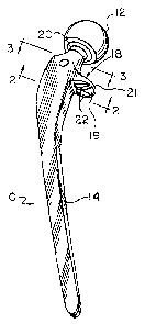
described in conjunction with a femoral component 10. It is ,
to be understood that component 10 can be implanted either
with or without cement. Component 10 includes a femoral head
12 and a femoral stem 14 which is adapted to be inserted into
a cavity formed in the medullary canal of a femur 16 (see
Fig. 13). Stem 14 includes a large, flat laterally extending
collar 18 having a lower surface 19. Surface 19 of collar 18
is adapted to rest on the cortical bone of the proximal femur
in the region of the natural femoral neck. Typically, head
12 is coupled to stem i4 by a Morse cone femoral neck 20
connected to collar 18. When head 12 is inserted onto neck
20, a very firm friction fit is formed, and no additional
fasteners are required. Head 12 may be readily removed by
proper twisting and pulling in the event it needs to be
changed or replaced for any reason after implantation,
Typically, stem 14 is held in place in the medullary
canal of the femur by the use of cement, such as a methyl
methacrylate cement. It is preferred that the mantle formed
by the cement surrounding stem 14 within the canal be of
approximately the same thickness on all sides of stem 14.
Thus, stem 14 should be centered within the canal. In
addition, it is highly desirable that accurate replication of
the anteversion selected during insertion of the trial
implants be achieved. Finally, stem 14 should not be
permitted to move while the cement is hardening.
To achieve these results, fins 22 are provided on lower
surface 19 of collar 18. Fins 22 are adapted to seat in
correspondingly formed slots or grooves 24 (Fig.l3) on
surface 46 (Fig.l4) of the proximal femur. To perform the
three functions set forth above, and to provide a
configuration that will perform these functions when used
with most femurs, regardless of strength, shape, size and
available bone surface, it is preferred that there be at
i
l ~:
i-- -~:-
WO 94/12123 ~CT/LJS93/11307
_9_
i
least two non-parallel fins 22 formed on lower surface 19 of
collar 18, or a single non-rectilinear fin having
non-parallel portions. In one embodiment as shown in Figs.
1-4, two separate, spaced fins 22 are provided. Each fin 22
has a length greater than its width and projects from lower
surf ace 19 of collar 18 . Prefer ably f ins 22 extend from the
outer edge 21 of collar 18 to a point where they almost touch
stem 14. In the embodiments of Figs. 1-4, fins 22 form an
acute angle with respect to ane another, but do not touch.
Fins 22 converge towards one another in the direction of stem ~
14, and diverge away from one another in the direction facing
away from stem 14.
Other embodiments of this invention are illustrated in
Figs. 5-8. With respect to Figs. 5 and 6, a single fan 30 is
provided on surface 19 of collar 18. Fin 30 has a curved,
semi-circular or semi-elliptical configuration in which ends
32 f ace outwardly away from stem T4 and the closed or curved
portion is adjacent item l4. Fin 30 can have any shape or
radius of curvature, so long as it is non-rectilinear and so
long as it extends a substantial distance across surface 21
of collar 18.
In Figs. 7 and 8, two fins 34 and 36 are provided. Fins
34 and 36 are generally orthogonal to one another, and
intersect one another at a single point. Preferably, fin 34
extends from edge 21 almost to the surface of stem 14, while
fin 36 traverses almost the entire distance laterally across
the surf ace 19 of collar 18. Fins 34 and 36 typically form a
plus sign or cross con''figuration. However, fins 34 and 36
could be disposed at an angle other than 90° with respect to
one another, so long as they are not parallel to one
another.
Fins 22, 30, 34 and 36 can be either milled from the
material of collar 18 and formed integrally therewith, or
they can be bonded or retrofitted to surface 19 of collar 18
after collar 18 has been formed. In the latter embodiment,
fins 22, 30 , 34 and 36 could be formed of methyl methacrylate
21.4~~~.s
~~
1V0 94112123 PCTIUS93/11307
-10-
cement which has been molded into the desired shape and
bonded to surface 19 of collar 18. ,
It will be appreciated that more than two fins could be
provided, or other configurations are possible, so long as
the fins pLevent both rotational movement of the implanted
stem 14 with respect to the femur and lateral movement of
stem 14 in a direction generally normal to the direction of
elongation of the femur. Moreover, the fins must have a
configuration which allows corresponding depressions to be
readily etched into surface 46 of the proximal femur. Also,
_ the fins must extend sufficiently far across surface 1.9 of
collar 18 that each fin, or each non-parallel portion of the
same fin, engages the bone in the proximal femur over a
sufficient distance to adequately prevent rotation and
lateral movement of stem 14. Preferably, the coverage of the
fins on surface 19 of collar 18 should. be sufficiently great
that all of these requirements are met for patients
regardless of the bone strength, configuration, mass or size
so that a standard design can be used with most patients.
The method of this invention and'the apparatus used to
implement this method will now be described with particular
reference to Figs. 9-14. It is to be understood that this
same method and apparatus can be used for a cemented or
uncemented implant. The tools employed include a rasp or
broach 40, mill guide 48, end mill or milling bit 70 and
clamp 92. Broach 40 is substantially similar to a
conventional broach used for enlarging the medullary Banal of
a femur. As previously indicated, broach 40 has the same
shape as stem 14, but is larger in size. The outer surface
of broach 40 is coaxial with the outer surface of stem 14, ,
but the distance between the central axis of broach 40 and
its outer surface is greater than the distance between the ,
central axis of stem 14 and its outer surface. Serrations 41
are provided along the outer surface of broach 40 for
assisting in the enlarging and cleaning out of the medullary
canal to from a cavity. Extending from an upper surface 44
_~~~~~~~
CVO 9./12123 PCTIUS93111307
--11-
of broach 40 is a shaft 42. Disposed near the upper end of
shaft 42 is a recess 50 into which a spring mounted ball (not
shown) on an attachment can seat far a snap-fit, A generally
circular hole 54 is formed on surface 44 adjacent shaft 42.
Mill guide 48 is used for forming grooves or slots 24 on
surface 46. Mill guide 48 includes machined slots 58 which
extend from an upper surface 62 to a lower surf ace 64 of mill,
guide 48. Mill guide 48 has the same number of slots 58 as
there are fins on collar 18. In addition, slots 58 have the
same general configuration as the fins on collar 18.
Disposed on upper surface 62 in association with each slot 58
is a semi-circular depression 60. Shaft 42 is intended to be
inserted into a channel 52 of mill guide 48, and a spring
mounted ball (not shown) in channel 52 provides a snug
snap-fit of mill guide 48 onto shaft 42.
Mi.Iling bit 70 is utilized to machine grooves 24.
Milling bit 70 has a rotatable shaft 74 and outer housing 72
which does not rotate and is coaxial with shaft 74. Proximal
end 76 of shaft 74 is adapted to be mounted into a chuck o~ a
conventional drill, while distal end '~8 is provided with a
milling tip which is adapted to cut bone. A shoulder 80
provided adjacent proximal end 76 limits axial movement of
shaft 74 with respect to housing 72. Generally spherical
ball 82 is disposed at the lower end of housing 72 and is
adapted to seat in depression 60 of mill guide 48.
'the uses of these tools to perform the method of the
present invention will now be described. Initially, the
femur is prepared for surgery in a conventional manner. Rasp
or broach 40 is used to clean out and enlarge the medullary
canal to form a cavity in the center of the femur to prepare
for insertion of stem 14, so that the outer surf aces of stem
14 are spaced a predetermined distance from the inner surface
of the cavity formed.
In a conventional manner, the upper surface of the
proximal femur is milled smooth and flush with the upper
surface 44 of broach 40 to provide a relatively flat surface
2~4~~1~
WO 94112123 PCTILJ593111307
--12-
46 on the proximal.femur upon which surface 19 of collar 18
can rest. This process is typically accomplished using a ,
large rotatable milling tool (not shown) which is mounted on
shaft 42 and is rotated by a conventional drill (not shown). .
Once surface 46 has been prepared as described, mill guide
48 is snapped onto shaft 42. Recess 50 cooperates with a
spring mounted ball (not shown) within channel 52 to hold
mill guide 48 snugly in place so that lower surface 64 is in
contact with surface 44. Peg 56 disposed on lower surface 64
resides in cooperatively formed hole 54 in surface 44 to
prevent mill guide 48 from rotating with respect to shaft 42.
A slot 58 is provided for each fin 22. Slots 58 of mill
guide 48 are configured to provide a slot or groove 24 on
surface 46 of the proximal femur which corresponds almost
precisely to the size and shape of the selected fins 22 or 30
or 34 and 36 to be provided on collar 18. If, for example,
fins 22 have the shape and configuration as shown in Fig. 1,
slots 58 would have the shape and configuration shown in Fig.
11. If, on the other hand, a fin 30 is to be utilized, a
single slot would be provided in mills guide 48 having the
same semi-circular shape or semi--elliptical configuration of
fin 30. In this event, only a single depression 60 would be
provided on surface 62 at roughly the center of the slot. If
fins 34 and 36 are to be utilized, two intersecting slots
would be provided in mill guide 48, and a single depression
60 would be disposed on surface 62 at the point of
intersection of the slots.
The manner of creation~of these slots or grooves 24 will.
now be described with reference to Figs. 10 and 12. Milling
bit 70 is utilized for this purpose. Shoulder 80 is pushed
into abutment with proximal end 84 of housing 72, and ball 82
is seated in cooperatively formed depression 60. Thereafter, ,
i
the drill is activated and distal end 78 of shaft 74
penetrates surface 46 of the proximal end of femur 16 to
substantially the same depth as fin 22 when surf ace 19 of
collar 18 rests on surf ace 46. Groove 24 is formed by
2~.4~~16 ~ , ,
:_.
~VO 94112123 PCTlUS93l11307
-13-
pivoting housing 72 about ball 82 to move shaft 74 back and
forth through slot 58 while shaft 74 is being rotated by a
drill (not shown). In this way, the cutting of each groove
24 is precisely controlled and each groove 24 is formed with
the desired location, depth and width.
Using this method, groove 24 will be deepest at a point
directly below depression 60 and shallowest at points spaced
farthest from depression 60 in a direction parallel to
surface 46. This groove 24 will have a somewhat arcuate
shape with a radius equal to the distance from the center of
ball 82 to the tip of distal end 78. Accordingly, fins 22,
30, 34 and 36 preferably have the same arcuate shape with the
same radius of curvature. Also, fins 22, 30, 34 and 36, if
viewed from the end, preferably have a U-shaped configuration
to conform to the U-shaped cross-sectional configuration of
recess 24 as formed by tip 78.
Once the foregoing process has been completed, and
grooves 24 have been formed, milling bit 70, mill guide 48
and broach 40 are all removed from the femur and stem 14 is
inserted as shown in Fig. 13. Fins X22 are inserted into
corresponding grooves 24, and preferably force is applied to
the upper surface of component 10 to drive it downwardly into
the femur so that fins 22 seat securely and tightly in
grooves 24. The insertion of stem 14 is accomplished in
conjunction with the provision of cement within the cavity in
the medullary canal within femur 16, in a conventional
manner. Fins 22 automatically center stem 14 within the
medullary danal~to produce a uniform mantle, to prevent
rotation of component 10 during the time the cement is
curing, and to produce precise replication of anteversion.
Another feature of this invention will now be described
with particular reference to Figs. 3, 4 and 14-16. As is
shown in Figs. 3 and 4, a depression 90 is formed in the
upper surf ace of collar 18. A clamp 92 is used in
conjunction with depression 90 to provide a downward force on
stem 14 while the cement is hardening to make certain that
~~~9~16
. ; , ; . . _~.. ~
- .. ,.:~;;.,
... ,
WO 9112113 PCT/1JS93/11307 ~
-14-
surface 19 of collar 18 is urged snugly against surf ace 46,
and that fins 22 are seated in corresponding grooves 24 so ,
that the resulting bond is tight and so that component l0 is
in precisely the desired rotational and lateral orientation. ,
Clamp 92 includes a stem 94 having an arcuate upper portion
96, a ball 98 secured to the distal end of upper portion 96,
a carriage 104, a flange 102 and a compression spring 100.
Stem 94 extends through a hole in carriage 104, and carriage
104 slides along stem 94. A set screw (not shown) in
carriage 104 rides in an axially extending slot along stem 94
(not shown) to limit axial travel of carriage 104, and to
prevent rotational movement of carriage 104 with respect to
stem 94. Carriage 104 includes one or more spikes 106, which
extend from one side thereof toward ball 98, and finger grips
105. Spring l00 is captured between carriage 104 and flange
102 and urges carriage 104 in a direction away from flange
102.
Use of clamp 92 will now be described with particular
reference to Fig. 14. Ball 98 is seated or nested in
depression 90 in collar 18. With a tY~umb pressing against
flange 102, and two fingers pressing downwardly on finger
grips 105, carriage 104 is withdrawn downwardly towards
flange 102. At the same time spikes 106 are driven into
engagement with the lesser trochantor. As the downward
pressure on carriage 104 is released, spikes 106 dig into the
lessor trochantor, and spring 100 biases stem 94 so that ball
98 is urged toward carriage 104. Spring 100 thereby applies
a downward pressure to~ball 98 which then urges component 10
downwardly to properly seat stem 14 within femur 16. Clamp
92 is removed once the cement has properly hardened. Removal .
is accomplished by compressing spring 100 between carriage
104 and flange 102 and withdrawing spikes 106 from the lessor
trochantor.
Clamp 92 applies the requisite seating force to component
l0 with little damage to the bone or surrounding tissues.
Clamp 92 is easily operated and readily removed by the
physician.
;~-.
T:,';:
di~'O 94112123 PCT/US93111307
-15-
Another embodiment of this invention will now be
described with reference to Figs. 17-19. This embodiment can
be used either with or withaut cement. Like numbers are used
for like parts, where applicable. In this embodiment, fins
again are disposed on surface 19 of collar 18 of component
10. These fins may have any one of the shapes previously
described, particularly with respect to Figs. 2-8. In this
embodiment, as in the previous embodiments, corresponding
grooves are cut into surface 46 of the proximal femur for
accepting the fins, prior to implantation of the component.
_ This embodiment differs from that of Figs. 9-12 in the manner
of formation of the grooves for accepting the fins.
In this embodiment, instead of mill guide 48, a stamp 120
is mounted onto shaft 42 of broach 40. Stamp I20 includes a
peg 122 which extends into hole 54 for proper orientation of
stamp 120 and for preventing rotation of stamp 120 during the
cutting process. Projections 126 on lower surface 124 of
stamp 120 have sharpened edges along the surface thereof
confronting surface 46 of the proximal femur. Projections
126 have precisely the same shape, orientation and size as
fins 22, 30 or 34 and 36 disposed on surface 19 of collar
18. Once stamp 120 has been mounted onto shaft 42, stamp 120
is driven downwardly against surface 46 by a hammer 132, or
other like tool for applying force, to drive projections 126
into surface 46 of the proximal femur. This operation stamps
into surface 46 grooves which have exactly the same size,
shape and orientation as selected fins 22, 30 or 34 and 36.
Once surface 124 has been driven into firm and uniform
contact with surface 44, stamp 120 and broach 40 are
removed. Component l0 is thereafter inserted as previously
described, so that the fins seat in the grooves formed in
surface 46 of the proximal femur. Thereafter, the
implantation process is completed, precisely as described
previously with respect to the embodiments of Figs. 9-12.
Typically, shaft 42, mill guide 48, shaft 74 of milling
bit 70, clamp 92 and plate 120 are all formed of a hard,
214~~1~
-
WO 94/12123 ' PCTI11S93111~0~
--16-
corrosion resistant material such as stainless steel.
However, other known, hard materials may be used. For ,
purposes of illustration only, typical dimensions of the fins
of this invention will be provided. However, it is to be .
understood, that by providing such examples, the scope of the
invention is in no way limited. In a typical implant, fins
22 would each have a length of about 1 cm and a width of
about 1 mm. Fin 30 would have an approximate radius of
curvature of 1 crn and a total length between ends 32 of about
15 mm. Fins 34 and 36 would typically each have a length of
_ about 1 cm. The sizes and shapes of the tools used for
implantation, as described herein, would be selected in
accordance with the sizes and shapes of the particular femur
upon which the surgical operation is being performed.
The foregoing invention provides a method and apparatus
for centering a stem within the cavity in the medullary canal
of the femur, permitting accurate reproduction of
anteversion, preventing rotation once the prosthetic has been
seated, and clamping the prosthetic during seating to insure
a good cement bond. As a result, a uniform mantle of cement
is provided around the circumference of the stem which
optimizes load distribution between the bone-cement and
metal-cement interfaces, thus rendering less likely failure
due to non-evenly distributed stresses. Accurate
reproduction of anteversion improves the quality of the
implant and improves relative movement within the joint so
that the patient can enjoy more nearly normal and pain-free
activity. Itotationa~l control prevents false movement while
the cement is hardening insuring proper rotational
orientation and improving the chances of a better cement bond . .
and longer life for the prosthetic. Clamping during seating
also insures a better and tightly cemented bond. The method ,
and apparatus of this invention also have applicability to
uncemented components since they permit accurate reproduction
of anteversion and prevent rotational movement of the
prosthetic once it has. been implanted.
~14~~16
f~:; ~~~ , ,
CVO 9x/12123 PCT/US931ii307
-17-
Tn view of the above description, it is likely that
modifications and improvements will occur to those skilled in
the art which are within the scope of this invention. The
above description is intended to be exemplary only, the scope
of the invention being defined by the following claims and
their equivalents.