Note : Les descriptions sont présentées dans la langue officielle dans laquelle elles ont été soumises.
WO 95/12527 -~ ! ~ o ,~ 16 , PCT/LTS94/09035
ENCLOSED SLEEVE-TYPE CARRIER
Field of the Invention
This invention relates to article carriers which are
adapted to be loaded through the open ends of an interim
sleeve configuration. More particularly, it relates to an
end panel arrangement which facilitates closing the ends
of the carrier and allows the end corner portions of a
fully enclosed carrier to follow the contour of the
packaged articles.
Background of the Invention
Sleeve-type carriers are typically formed from a blank
which is delivered to a packaging machine in the form of
a collapsed sleeve. The sleeve is erected or opened in the
machine and articles are loaded through one or both ends
of the sleeve, after which the ends of the carrier are
closed. Formation of the end panels of the carrier
normally requires the top and bottom end panel flaps, and
the dust or glue flaps to which the end panel flaps are
glued, to be folded into place by separate folding steps.
When forming a fully enclosed carrier, such as one
used to package long neck bottles, the upper portions of
the end panels are often tapered so as to better follow the
contour of the end bottles. To accomplish this the side
panels are wider at the bottom than at the top, with the
lower portion of the side panels being of constant width
and the upper portion being tapered. The glue flaps hinged
to the end edges of the side panels are basically comprised
of a single flap containing a cutout extending in from the
outer edge of the flap to a point near the juncture of the
tapered upper end edge of the side panel and the straight
lower end edge portion. This creates a narrow connecting
strip between the upper and lower segments of the glue
flap. The cutout plus a score line in the connecting strip
allows the two segments of the glue flaps to shift as
necessary when folded into place in order to accommodate
the segments to the tapered shape of the end panels.
Because folding of the upper segment of the glue flaps is
resisted by the angled relationship of its fold line to the
fold line of the lower segment, a "kicker" wheel is
R'O 95/12527 PCT/US94/09035
~150'~1~
- -2-
normally required to overcome this resistance. Use of
kicker wheels, however, creates other problems. The impact
of the kicker wheels makes it more difficult to maintain
the carrier in square condition, and the time required for
the kicker wheels to fold the glue flaps in place makes it
necessary to reduce the machine speed.
It would be desirable to~be able to form a tapered
4
carrier without employing segmented glue flaps. By
utilizing a unitary glue flap the need for a kicker wheel
would be eliminated. It would also be desirable to have
a carrier which is capable of more closely following the
contours of bottles or other tapered articles in order to
more tightly hold the articles within the package.
Normally, the end panels of a sleeve-type carrier are not
capable of closely following the contour of necked bottles
in both the end panel area and in the corner areas between
the end and side panels. It is therefore an object of the
invention to provide a sleeve-type carrier that can provide
a tighter package and not slow the speed of the packaging
machine.
Brief Summary of the Invention
A sleeve-type carrier is provided with an end panel
comprised of transversely extending glue flaps and
overlying upper and lower end panel flaps. The lower end
panel flap is foldably connected to the bottom panel and
to gusset tabs. The tabs are also foldably connected to .
the glue flaps. This arrangement permits the carrier
sleeve to be loaded with articles when the lower end panel
flap is in its horizontally open position, and causes the
glue flaps to automatically move into closed position when
the lower end panel flap is moved first to an open vertical
position, then to its closed position. The tabs are folded
about their fold lines so that they are in face-to-face
relationship with the interior face of the end panel flap
and with the exterior face of the associated glue flap.
In addition, means are provided for causing the end panels
to tightly hold adjacent curved or tapered articles in
place. The lower end panel flap fold line preferably has
WO 95/12527 PCT/US94/09035
_3_
a length less than the width of the bottom panel.
In one embodiment the means for causing the end panels
to tightly hold adjacent curved or tapered articles in
place comprises bevel panels foldably connected to the
adjacent glue flap and side panel and having a greater
width at the top than at the bottom. In another embodiment
the means comprises a first glue flap fold line connecting
a lower portion of the glue flaps to an associated side
panel and a second glue flap fold line connecting an upper
portion of the glue flaps to the associated side panel,
each second glue flap fold line forming an angle with the
associated first glue flap fold line and being angled
toward the opposite end panel.
The carrier design permits unitary glue flaps to be
employed even though the package is tapered to conform to
the outline of the articles inside. In addition, the
automatic closure of the flaps due to the action of the
gusset panels does away with the need to employ kicker
wheels to close the glue flaps.
The above and other aspects and benefits of the
invention will readily be apparent from the more detailed
description of the preferred embodiments of the invention
which follows.
Brief Description of the Drawing
FIG. 1 is a pictorial view of the carrier of the
invention;
FIG. 2 is a plan view of a blank used to form the
carrier;
FIG. 3 is an enlarged view of the portion enclosed by
the oval 3 of FIG. 2;
FIG. 4 is a pictorial view of an open end of a carrier
sleeve in condition to be loaded with articles;
FIG. 5 is a pictorial view of the open end of the
carrier sleeve of FIG. 4, with the lower end panel flap
shown in vertically lowered position and the glue flaps in
partially closed position;
FIG. 6 is a pictorial view of the open end of the
carrier sleeve of FIG. 4, with the end panel flap shown in
PCT/US94/09035
wo 95n25z~
' -4-
interim horizontal position in the course of being moved
into final closed position;
FIG. 7 is a partial side elevation of the carrier;
FIG. 8 is an enlarged partial perspective of the
carrier, with portions of the upper end panel flaps removed
in order to view the folded glue flaps; .
FIG. 9 is a plan view of a modified carrier blank;
FIG. 10 is a pictorial view of~a carrier formed from
the modified blank of FIG. 9; and
FIG. 11 is an enlarged partial perspective of the
modified carrier, with the upper end panel flaps and
portions of the top panel removed in order to view the
folded glue flaps.
Detailed Description of the Preferred Embodiments
Referring to FIG. 1, a carrier 10 embodying the
invention includes side panels 12 connected to top panel
14 and to a bottom panel, not visible in this view. The
carrier includes end panels 16 which are comprised of glue
flaps 18 extending transversely from the side panels 12,
and upper and lower end panel flaps 20 and 22,
respectively, overlying the glue flaps. Bevel panels 24 .
connect the glue flaps 18 to the side panels 12. The end
panels and bevel panels snugly engage the cylindrical
contour of adjacent bottles while also tapering in from the
barrel of the bottle to the bottle cap to provide a very
tight package.
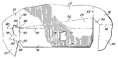
The carrier is formed from the blank 26 shown in FIG.
2, wherein like reference numerals to those used in FIG.
1 refer to similar elements. The blank is comprised of
flexible sheet material of suitable strength, such as
paperboard of conventional carrier thickness, divided into
various sections. A bottom panel section 28 is connected
to the side panel sections 12 by fold lines 30, and a top
panel section 32 is connected to each of the side panel
U
sections by fold lines 34. Each top panel section includes
a handle opening 36 covered by a hinged flap 38. Upper end
panel flaps 40, which are adapted to overlap to form the
upper end panel flaps 20 of the carrier, are connected to
WO 95/12527 PCT/US94/09035
the side edges of the top panel sections 32 along fold
lines 42, and the lower end panel flaps 22 are connected
to the edges of the bottom panel section 28 along fold
lines 46. In addition, the glue flaps 18 are connected to
5 the bevel panel sections 24 by fold lines 50, and the bevel
panel sections in turn are connected to the side panel
sections 12 by diagonal fold lines 52. It can be seen that
the top edge of the side panel sections, represented by
fold line 34, is shorter than the bottom edge, represented
by the fold line 30, so that the side edges of the side
panels angle out toward the bottom of the carrier. Also,
the ends of the fold lines 42 of the upper end panel flaps
40 connect with the ends of the fold lines 34 by diagonal
edges 54. Although the fold lines 50 appear to be at right
angles to the top and bottom edges of the side panel
sections, they preferably form a slight angle with these
edges in order to more readily fold in around an adjacent
bottle in the package.
Referring to FIG. 3 as well as FIG. 2, the lower end
panel flaps 22 are connected to the adjacent glue flaps 18
by a gusset panel or tab 56. The tabs 56 are connected to
the lower end panel flaps 22 along fold lines 58 located
intermediate the fold line 46 and the end of the lower end
panel flap 20, and to the glue flaps 18 at the end portion
of the glue flap edge~60 along fold line 62. The tab fold
lines 62 are substantially aligned with the fold lines 30,
while the tab fold lines 58 are angled out so that the fold
lines 58, if extended, would form an acute angle with
extensions of the fold lines 62. The configurations of the
tabs 56, the lower end panel flaps 22 and the bottom panel
section 28 are such that cutouts 64 are defined by spaced
edge portions of these elements and the edge 60 of the glue
flaps 18, an arrangement made possible by the fact that the
fold line 46 is shorter than the width of the bottom panel.
The cutouts extend through the intersection 66 of the fold
lines 30, 50 and 52. Because the tab fold lines 58 are
spaced from the side edges of the lower end panel flap 22,
the lower edge of the tab is formed by slits 68 in the
WO 95!12527 PCT/US94/09035
215 4'~ 1 ~
lower end panel flap. If the side edge of the lower end
panel flap extended down directly from the lower end of the
tab fold line 58, there of course would be no need for the
slits.
The glue flaps 18 may also include a shoulder cutout
or opening 70 located so as to be opposite the upper edge
or shoulder of the barrel of an acl~j~acent bottle in a
package. Spaced fold lines 72 and'74~connect the cutout
to the outer edge of the glue flap~l8, while fold line 76
connects the opposite end of the cutout to the fold line
50. The fold line 72 preferably is at right angles to the
outer edge of the glue flap, while fold line 74 is angled
in the upper portion of the flap. The fold line 76
preferably is at the same angle as the fold line 74 and is
an extension of that fold line.
To form a carrier from the blank, one of the side
panel sections 12 is folded in about its fold line 30 and
the remote top panel section 32 is folded in about fold
line 34 so that adhesive on the top panel section adjacent
the folded side panel section, illustrated in FIG. 2 by the
stippling at the right of the blank, adheres the overlapped
top panel sections together. This results in a collapsed
sleeve, which is subsequently introduced to a packaging
machine where the sleeve is squared up and erected in a
manner well known in the art. The resulting erected sleeve
is illustrated in FIG. 4, wherein the lower end panel flap
22 is substantially an outward extension of the bottom
panel 28, and the glue flaps 18 and bevel panel 24 are
extensions of the side panels 12. The upper end panel flap
20, formed from the overlapping adhered flaps 40, typically
is folded up at this point so as not to interfere with the
introduction of the articles to be packaged.
After the articles, such as the long necked bottles
B, have been loaded, the end panels are closed by first
pivoting the lower end panel flap 22 down so that it forms
substantially~a right angle with the bottom panel 28. As
shown in FIG. 5, downward movement of the lower end panel
flap 22 causes the gusset tabs 56 to fold up about their
R'O 95/12527 PCT/US94/09035
fold lines 58, which in turn causes the glue flaps 18 and
the bevel panel 24 to pivot inwardly as a unit about the
bevel panel fold lines 52 to a position somewhat short of
their fully closed position. This movement of the glue
flaps brings the fold lines 62 of the gusset tabs 56 into
substantially horizontal position, so that when the lower
end panel flap 22 is subsequently pivoted back up into its
original open position, as shown in FIG. 6, the tabs 56
fold up about the fold lines 62. This causes the glue
flaps 18 and connected bevel panels 24 to move to their
final closed position in which the glue flaps are
substantially at right angles to the side panels and the
top edges of the bevel panels are directly beneath the
diagonal edges 54 of the top panel. It will be understood
that the biases created at the fold lines 58 and 62 by this
folding action result in the gusset tabs and glue flaps
being essentially locked into place.
The final step in closing the ends of the carrier in
order to produce the package of FIG. 1 is to fold the lower
end panel flaps 22 up about their fold lines 46 and the
upper end panel flaps 20 down about their fold lines 42 to
adhere them to the glue flaps 18 by adhesive applied to the
end portions of the upper and lower end panel flaps. The
adhesive will preferably be applied to the gusset tabs 56
as well, to adhere both the tabs and the lower end panel
flaps directly to the glue flaps. As can be seen from FIG.
6, the tabs 56 in the final carrier configuration will lie
directly between the lower end panel flap 22 and the glue
flaps 18 in face-to-face relationship with both.
Referring now to FIG. 7 in addition to FIGS. 1-6, the
angled fold lines 52 between the bevel panels 24 and the
side panels 12 permit the bevel panels to flex around the
curved contours of adjacent bottles and to contact the
bottles at an angle designed to engage both the shoulder
of the bottles and the tops of the bottles. The bottom
portions of the glue flaps 18 extend at substantially right
angles to the side panels so that the bottom edges of the
glue flaps can be in contact with the bottom panel.
R'O 93/12527 PC~'IUS94/09035
2~.50°~1~
_8_
Because the fold line 50 is at a slight angle to the bottom
fold line 30, the glue flaps lie at a slight angle to the
vertical in the carrier, which results in the adhered end
panel flaps to also take on the same angle. The bottom
portions of the end panels thus follow the slightly tapered
shape of the barrel of the bottles.
In addition, as shown better in FIG'.~~'8, the shoulder
cutouts 70 and the related fold lines~~.~l, 74 and 76 allow
the glue flaps to fold or flex inthis area. The end
panels of the package are therefore able to taper in to the
tops of the bottles, providing for a tight package. By
providing cutouts, the length of the fold lines is reduced,
thereby offering less resistance to the flexing of the glue
flaps. In addition to providing this function, the cutouts
allow the glue flaps to follow the contour of the shoulder
of adjacent bottles, with the edges of the cutouts
providing a "bite" to better grip and hold the bottles in
place. It should be understood that the particular shape
and location of the cutouts 70 are functions of the contour
of the packaged bottles, and as such may be different than
as illustrated in the drawing. Although preferred when the
contour of the bottles is such that the cutouts promote a
tighter fit of the glue flaps against the bottles, the
carrier of the invention need not always be provided with
them. For example, they are not essential when a tight
closure can be obtained without them.
Referring now to FIG. 9, a modified blank is
illustrated which differs from the first embodiment
primarily in the design of the glue flaps. As in the first
embodiment, the bottom panel section 28 is connected to
side panel sections 12 by fold lines 30, and to lower end
panel flaps 22.by fold lines 46. The side panel sections
12 are connected to top panel sections 32 by fold lines 34,
and the top panel sections include upper end panel flaps
40. In this embodiment, however, the glue flaps 80 are
shaped differently from the glue flaps of the first
embodiment and there are no bevel panels. Instead, the
glue flaps 80 are connected to the side panel sections by
WO 95/12527 PCT/US94/09035
_g_
a first fold line 82, which is an extension of the fold
line 46, and a second fold line 84, which extends from the
end of the first fold line 82 to the end of the fold line
34. As in the first embodiment, the glue flaps 80 are
connected to the lower end panel flaps 22 by gusset panels
or tabs 56, and cutouts 64 are defined by spaced edge
portions of the glue flap 80, the lower end panel flap 22
and the bottom,panel section 28. The glue flaps 80 may
also include a shoulder cutout or opening 86 located so as
to be opposite the upper edge or shoulder of the barrel of
an adjacent bottle in a package. Spaced fold lines 88, 90
and 92 connect the cutout 86 to the outer edge of the glue
flap 80 to promote flexing or bowing, as described in more
detail below.. Note that the fold lines 90 and 92 are
illustrated as slits which are spaced from the cutout 86
and the edges of the glue flap 80. Slits are preferred in
many cases as they facilitate bowing of the glue flap to
a greater degree than conventional fold lines. The fold
line 88 is illustrated as a conventional fold line since
it is too short to consist of a single elongated slit.
The modified carrier of FIG. 10 is fabricated from the
blank in the manner described in connection with the first
embodiment, following the steps illustrated in FIGS. 4, 5
and 6. However, in this case when the glue flaps 80 are
folded in they fold about both the angled fold lines 82 and
84. The lower portion of a flap 80 tends to pivot about
the fold line 82, while the upper portion tends to pivot
about the fold line 84. The material of the flaps in the
transition area between the upper and lower portions thus
is subjected to stresses tending to move it in different
directions, causing the flaps to slightly buckle or bow in
this area. This biases the flaps inwardly toward the
closed position shown in FIG. 11, and causes them. to
conform to the shape of the adjacent bottles. Although the
fold lines 88, 90 and 92 and the cutout 86 enhance the
ability of the flaps to flex and conform to the bottle
contours, they are not essential to the functioning of the
glue flaps since even without them the glue flaps will
WO 95/12527 PCT/US94/09035
215 ~'~ ~. ~ _ l o _ ~'
still have this ability as a result of the dual angled fold
lines 82 and 84 about which the glue flaps pivot.
It will now be appreciated that the invention provides
for automatic closing of the glue flaps as a result of the
pivoting movement of the end panel flaps, which is made
possible by the gusset tabs that connect the lower end r
panel flaps to the glue flaps. By employing unitary glue
flaps while still being able to form~~=a package having
tapered end panels, there is no longer-~a~ need to use kicker
~w-.
wheels to close the glue flaps. ~~lie unique glue flap
arrangement provides for engagement of the end panels with
the tapered portions of adjacent bottles between the caps
and the barrel, while the bevel panel of the first
embodiment or the dual fold line of the glue flaps in the
second embodiment provide a snug fit around the curved
contour of the corner bottles.
It should now be apparent that the invention is not
necessarily limited to all the specific details described
in connection with the preferred embodiments, but that
changes to certain features of the preferred embodiments
which do not alter the overall basic function and concept
of the invention may be made without departing from the
spirit and scope of the invention defined in the appended
claims.