Sélection de la langue

Search

Sommaire du brevet 2151185 

Énoncé de désistement de responsabilité concernant l'information provenant de tiers

Une partie des informations de ce site Web a été fournie par des sources externes. Le gouvernement du Canada n'assume aucune responsabilité concernant la précision, l'actualité ou la fiabilité des informations fournies par les sources externes. Les utilisateurs qui désirent employer cette information devraient consulter directement la source des informations. Le contenu fourni par les sources externes n'est pas assujetti aux exigences sur les langues officielles, la protection des renseignements personnels et l'accessibilité.

Disponibilité de l'Abrégé et des Revendications

L'apparition de différences dans le texte et l'image des Revendications et de l'Abrégé dépend du moment auquel le document est publié. Les textes des Revendications et de l'Abrégé sont affichés :

  • lorsque la demande peut être examinée par le public;
  • lorsque le brevet est émis (délivrance).
(12) Brevet: (11) CA 2151185
(54) Titre français: JOINT PREFABRIQUE POUR TABLEAU DE BAIE
(54) Titre anglais: PREFABRICATED REVEAL JOINT
Statut: Durée expirée - au-delà du délai suivant l'octroi
Données bibliographiques
(51) Classification internationale des brevets (CIB):
  • E04B 01/38 (2006.01)
  • E04F 13/06 (2006.01)
(72) Inventeurs :
  • STARK, THOMAS S. (Etats-Unis d'Amérique)
  • GRETZ, THOMAS J. (Etats-Unis d'Amérique)
(73) Titulaires :
  • PLASTIC COMPONENTS, INC.
(71) Demandeurs :
  • PLASTIC COMPONENTS, INC. (Etats-Unis d'Amérique)
(74) Agent: GOWLING WLG (CANADA) LLP
(74) Co-agent:
(45) Délivré: 2005-08-02
(22) Date de dépôt: 1995-06-07
(41) Mise à la disponibilité du public: 1995-12-16
Requête d'examen: 2002-04-08
Licence disponible: S.O.
Cédé au domaine public: S.O.
(25) Langue des documents déposés: Anglais

Traité de coopération en matière de brevets (PCT): Non

(30) Données de priorité de la demande:
Numéro de la demande Pays / territoire Date
08/260,070 (Etats-Unis d'Amérique) 1994-06-15

Abrégés

Abrégé français

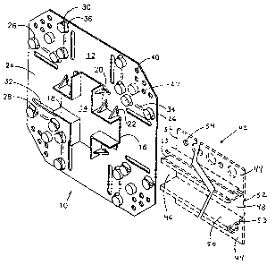
Un ensemble de joint préfabriqué moulé d'une seule pièce de plastique et utilisé pour raccorder des canaux décoratifs ou tableaux de baie sur l'extérieur des bâtiments. Les tableaux de baie sont généralement utilisés pour former un effet esthétiquement agréable sur la surface extérieure d'un bâtiment qui est recouverte de stuc, mortier, ciment, plâtre, placoplâtre ou similaire. Cette invention offre un joint relativement peu coûteux qui simplifie grandement le travail de jointure des tableaux de baie sur les chantiers.


Abrégé anglais

A prefabricated joint assembly molded of a single piece of plastic and used for connecting decorative channels or reveals on the exteriors of buildings. Reveals are typically used to form an aesthetically pleasing effect on the exterior surface of a building that will be covered with stucco, mortar, cement, plaster, drywall, or the like. This invention provides a relatively inexpensive joint that vastly simplifies the job of joining reveals at the construction site.

Revendications

Note : Les revendications sont présentées dans la langue officielle dans laquelle elles ont été soumises.


What is claimed is:
1. A one piece joint assembly, comprising:
a base plate;
a raised portion having an outer periphery integral
with said base plate and walls integral with and extending
from the outer periphery of said raised portion
perpendicular to said base plate and defining a mating
abutting channel for receiving a reveal; and
guide members integral with and extending from said
base plate to provide for the insertion and guidance of a
reveal until it abuts with said mating abutting channel.
2. The joint assembly of Claim 1, wherein said guide
members are buttons which contain a groove having a face
and an overhanging lip defined by said groove, said groove
being formed along one side of said guide button to help
define a trackway for insertion of a reveal.
3. The joint assembly of Claim 2, comprising both
innermost and outermost guide buttons and guide ridges
between said innermost and said outermost guide buttons,
said guide ridges further guiding insertion of said reveal
in said trackway as said reveal is inserted past said
outermost guide buttons.
4. The joint assembly of Claim 1 wherein said
intersection of a plurality of channels is a cross shape
for accommodating the joining of four reveal ends.
5. The joint assembly of Claim 1 wherein said
8

intersection of a plurality of channels is in a "T" shape
for accommodating the joining of three reveal ends.
6. The joint assembly of Claim 1 wherein said
intersection of a plurality of channels is in an "L" shape
for accommodating the joining of two reveal ends.
7. A method of forming a decorative reveal grid
pattern comprising the steps of:
providing a plurality of one-piece joint assemblies
each having trackways defined by guide members;
creating a grid starting point by fixing a one-piece
joint assembly in place;
cutting reveals to length from indeterminate lengths
using a square cut;
inserting the end of said square cut reveal into each
trackway leading into said one-piece joint assembly;
fixing said reveals in place;
continuing the process of joining one-piece joint
assemblies and reveals until a grid pattern is completed on
the wall of a structure; and
spreading stucco, cement, plaster, mortar, drywall or
the like exteriorly of said channels formed by said reveals
and said one-piece joint assemblies until an even surface
is obtained that is interrupted only by the open channels
of the reveals and joint assemblies.~
8. ~The method of Claim 7 wherein said one-piece joint
assemblies comprise:
9~~

a base plate;
a raised portion having an outer periphery integral
with said base plate and walls integral with and extending
from the outer periphery of said raised portion
perpendicular to said base plate and defining a mating
abutting channel for receiving a reveal; and
guide members integral with and extending from said
base plate to provide for the insertion and guidance of a
reveal until it abuts with said mating abutting channel.
9. A complete joint comprising:
a one-piece joint assembly affixed in place and having
a base plate, a raised portion having an outer periphery
integral with said base plate, walls integral with and
extending from the outer periphery of said raised portion
perpendicular to said base plate and defining a mating
abutting channel for receiving a reveal, and guide members
integral with and extending from said base plate to provide
for the insertion and guidance of a reveal until it abuts
with said mating abutting channel;
one or more reveals having square cut ends affixed in
place with said square cut ends of said reveals inserted
fully into said one-piece joint assembly and having holes
in flanges of said reveals lining up with slots in said
base plate of said one-piece joint assembly; and
plaster, stucco, mortar, cement or similar paste
applied over said one-piece joint assembly and outside of

channels of said reveals, said paste flowing through said
flanges of said reveals and said slots lined up with said
holes in said reveals, thereby keying or holding said one-
piece joint assembly and said reveals firmly in place.
11

Description

Note : Les descriptions sont présentées dans la langue officielle dans laquelle elles ont été soumises.


2151185
PREFABRICATED REVEAL JOINT
FIELD OF THE INVENTION
This invention relates to construction materials for
walls of buildings, and in particular, to a prefabricated
joint for connecting decorative channels or reveals.
Reveals are typically used to form an aesthetically
pleasing effect on the exterior surface of a building that
will be covered with stucco, mortar, cement, plaster,
drywall, or the like. This invention provides a relatively
inexpensive and easy to use joint construction.
BACKGROUND OF THE INVENTION
The use of channels as reveals to form aesthetically
pleasing looks on wall surfaces is well known. Presently,
the reveals are constructed of typically aluminum or
plastic materials such as polyvinyl chloride (PVC).
For aluminum reveals, prefabricated joints are
presently accomplished by cutting the ends of each reveal
which will be joined to a proper adjoining angle, abutting
the cut ends, and welding the adjoined edges to form a
joint.
For plastic or aluminum reveals, joints are presently
prefabricated by mitering the reveal sections so that they
will properly abut, placing the sections in proper abutting
relationship, applying waterproofing such as adhesive tape
to the back side of the abutting sections and applying glue
1

215115
or other similar adhesive or welding to obtain joint
rigidity.
The disadvantage with the present art of prefabricated
reveal joints is that they require precise mitered cuts,
lack integral alignment of the reveals with the joint, and
it is possible for the joint to have water leakage if the
aluminum joints are not properly welded and sealed together
or if the plastic joints are not properly taped and glued.
SUMMARY OF THE INVENTION
The object of the invention is to~provide a
prefabricated joint which is inexpensive to manufacture,
easy to apply in the field, and of one piece molded
construction to prevent water leakage from occurring at the
joint.
The joint is typically injection molded of PVC or
similar plastic and contains trackways that allow the
flanges of the reveal base to slidingly enter the joint
until the channel of the reveal properly abuts the channel
of the joint. Several types of joints may be formed for
accommodating the various juncture points for the reveals,
such as cross-joints, T-joints, L-joints, butt-joints,
inside corners, or outside corners. After being joined in
the field, the PVC trackway of the prefabricated joint --
envelops the abutted ends of the channel of the reveal and
the channel of the joint, allowing a water tight fit
2

21~~1~5
without the use of adhesive or caulking.
DESCRIPTION OF THE DRAWINGS
Fig. 1 is a perspective view of a cross-joint and a
typical reveal in phantom lines as it would be lined up
prior to slidingly engaging it in the trackway of the
joint.
Fig. 2 is a perspective view of a portion of a reveal.
Fig. 3 is a perspective view of another embodiment of
the present invention, a T-joint.
Fig. 4 is a perspective view of another embodiment of
the present invention, an L-joint.
DESCRIPTION OF THE INVENTION
A prefabricated cross-joint 10 in accordance with the
present invention is shown in Fig. 1. The cross-joint 10
is of one-piece molded construction and is typically formed
of a plastic material such as PVC. The cross-joint 10 has
walls 18 formed perpendicular to a base plate 12. Eight
such walls 18 define a cross junction. Angular ribs 20
support the walls 18 and rib supports 22 stiffen the
angular ribs 20 to keep the walls from flexing and in a
proper perpendicular relationship to the base 12.
Four trackways are defined on the cross-joint 10 by -
the base plate 12 forming a track bottom surface 24 and a
plurality of inner 27 and outer 26 guide buttons. Two
3

21511~~
outer guide buttons 26 and two inner guide buttons 27
define each trackway for the four reveals which will be
joined at the cross-joint. Each guide button has a track
guide surface 28 formed by the semi-circular cutout 36 in
the guide button. An overhanging lip 30 which is formed by
the cutout also serves to form the trackway and guide the
reveal.
A reveal 42, also shown in Fig. 1, consists of a base
plate 48 having outward extending flanges 44, a channel 46
defined by channel walls 50 perpendicular to the base plate
48. The end of the channel 46 is defined by edges 53 of
the channel walls 50 and edge 52 of the base plate 48.
When applied in the field, the cross-joint 10 would
typically be nailed or tied into place through one of the
holes 40 in the base plate 12. Nails are typically used to
fasten the cross-joint 10 to concrete substrates and wire
is typically used to tie the cross-joint 10 to metal or
plastic lathe substrates. A reveal would then typically be
cut square to the correct length and one end inserted into
the trackway defined by the track bottom surface 24 and the
guide buttons with their semi-circular cutouts 36. The
square cuts are the easiest to make and no miter or angle
cuts are needed when the invention is used.
Reveal 42 is shown in Fig. 1 aligned in the proper
position for insertion into a trackway. As reveal 42 is
inserted, the base edge 52 of the reveal enters and is
4

~1~~1~5
guided by the trackway formed by the track bottom surface
24 and the track guide surface 28 formed by the semi-
circular cutout 36 in the outer guide buttons 26. The
overhanging lip 30 acts to hold the reveal 42 against the
track bottom surface 24. As the reveal 42 is advanced past
the outer guide buttons 26 it is further held in the track
by a ridge 34 positioned on base plate 12 between the outer
and inner guide buttons. As the reveal 42 is advanced past
the ridge 34 it is guided into proper position by the inner
guide button 27 with semi-circular cutout 36, track guide
surface 28, and overhanging lip 30 which further defines
the trackway. At full insertion the leading edge 52 of the
reveal base plate 48 abuts the base edge 16 of the
intersection 14 and the reveal side wall edge 53 abuts the
intersection side wall edge 17. The location of the guide
buttons is such that the sliding fit of the reveal 42 is a
tight fit so that when fully inserted, reveal 42 is held in
place against base edge 16 and side wall edge 17 of
intersection 14.
After all four reveals are inserted fully into the
trackways of cross-joint l0 and are fixed in place, stucco
or other similar filling material is spread on the exterior
of the channel 46 of the reveal and the exterior of the
intersection 14. The holes 40 in the base plate 12 of theca
cross-joint 10 and the holes 54 in the flanges of the
reveal 42 are used for keying, or holding the stucco in
5

211185
place. As stucco is spread on the exterior of the channels
and intersection, some stucco enters the holes that have
not been filled with nails or similar fastening devices,
thereby allowing the stucco to hold a firm grip on the area
surrounding the channel. Slots 32 formed in the base plate
12 of cross-joint 10 line up with the holes 54 in the
inserted reveals, allowing stucco to flow through the holes
54 in the reveal 42 and also through the slot 32 giving
better adhesion of the stucco at the juncture of the
reveals and intersection.
In its finished state, the channel and the interior of
the intersection would be visible and the area surrounding
it would contain an even layer of stucco or other similar
materials such as mortar, cement, plaster, or drywall. The
channel and interior of the intersection may be painted a
contrasting color if desired.
Fig. 2 is a perspective view of a reveal 42 showing
the channel 46 formed by the reveal base plate 48 and
channel walls 50. The reveal base edge 52 and channel wall
edge 53 are depicted as are the reveal flanges 44 and holes
54 in the flanges.
Fig. 3 is a perspective view of another embodiment of
the present invention, a T-joint 56. The T-joint 56 is
similar to the cross-joint of Fig. 1 except only three w
trackways instead of four are used for the insertion of
reveals. Three reveals will be inserted in the three
6

21511b5
trackways to form a "T" joint defined by five walls 18
extending from the base plate 12. All other numbered parts
in Fig. 3 are analogous to the same parts shown in Fig. 1.
Fig. 4 is a perspective view of another embodiment of
the present invention, an L-joint 58. The L-joint 58 is
similar to the cross-joint of Fig. 1 and the T-joint of
Fig. 2 except only two trackways are used for the insertion
of reveals. Two reveals will be inserted in the two
trackways to form an "L" joint defined by four walls 18
extending from the base plate 12. All other numbered parts
in Fig. 4 are analogous to the same parts shown in Figures
1 and 3.
Similarly, a butt-joint, inside corner and outside
corner may be provided utilizing the concepts of the
invention.
The invention provides one-piece precision joints that
enables field placement of screed channels or reveals with
only simple square cuts at watertight intersections.
Having thus described the invention with reference to
several embodiments, it is to be understood that the
invention is not so limited by the description herein but
is defined as follows by the appended claims.
7

Dessin représentatif
Une figure unique qui représente un dessin illustrant l'invention.
États administratifs

2024-08-01 : Dans le cadre de la transition vers les Brevets de nouvelle génération (BNG), la base de données sur les brevets canadiens (BDBC) contient désormais un Historique d'événement plus détaillé, qui reproduit le Journal des événements de notre nouvelle solution interne.

Veuillez noter que les événements débutant par « Inactive : » se réfèrent à des événements qui ne sont plus utilisés dans notre nouvelle solution interne.

Pour une meilleure compréhension de l'état de la demande ou brevet qui figure sur cette page, la rubrique Mise en garde , et les descriptions de Brevet , Historique d'événement , Taxes périodiques et Historique des paiements devraient être consultées.

Historique d'événement

Description Date
Inactive : Périmé (brevet - nouvelle loi) 2015-06-07
Inactive : CIB de MCD 2006-03-11
Accordé par délivrance 2005-08-02
Inactive : Page couverture publiée 2005-08-01
Inactive : Grandeur de l'entité changée 2005-05-26
Inactive : Taxe finale reçue 2005-05-18
Préoctroi 2005-05-18
Un avis d'acceptation est envoyé 2005-03-10
Lettre envoyée 2005-03-10
Inactive : Approuvée aux fins d'acceptation (AFA) 2005-02-25
Lettre envoyée 2002-05-02
Inactive : Renseign. sur l'état - Complets dès date d'ent. journ. 2002-05-02
Inactive : Dem. traitée sur TS dès date d'ent. journal 2002-05-02
Toutes les exigences pour l'examen - jugée conforme 2002-04-08
Exigences pour une requête d'examen - jugée conforme 2002-04-08
Demande publiée (accessible au public) 1995-12-16

Historique d'abandonnement

Il n'y a pas d'historique d'abandonnement

Taxes périodiques

Le dernier paiement a été reçu le 2005-05-18

Avis : Si le paiement en totalité n'a pas été reçu au plus tard à la date indiquée, une taxe supplémentaire peut être imposée, soit une des taxes suivantes :

  • taxe de rétablissement ;
  • taxe pour paiement en souffrance ; ou
  • taxe additionnelle pour le renversement d'une péremption réputée.

Les taxes sur les brevets sont ajustées au 1er janvier de chaque année. Les montants ci-dessus sont les montants actuels s'ils sont reçus au plus tard le 31 décembre de l'année en cours.
Veuillez vous référer à la page web des taxes sur les brevets de l'OPIC pour voir tous les montants actuels des taxes.

Historique des taxes

Type de taxes Anniversaire Échéance Date payée
TM (demande, 2e anniv.) - petite 02 1997-06-09 1997-06-06
TM (demande, 3e anniv.) - petite 03 1998-06-08 1998-06-08
TM (demande, 4e anniv.) - petite 04 1999-06-07 1999-06-02
TM (demande, 5e anniv.) - petite 05 2000-06-07 2000-06-07
TM (demande, 6e anniv.) - petite 06 2001-06-07 2001-04-06
Requête d'examen - petite 2002-04-08
TM (demande, 7e anniv.) - petite 07 2002-06-07 2002-04-19
TM (demande, 8e anniv.) - petite 08 2003-06-09 2003-06-06
TM (demande, 9e anniv.) - petite 09 2004-06-07 2004-04-05
Taxe finale - générale 2005-05-18
TM (demande, 10e anniv.) - générale 10 2005-06-07 2005-05-18
TM (brevet, 11e anniv.) - générale 2006-06-07 2006-06-02
TM (brevet, 12e anniv.) - générale 2007-06-07 2007-06-05
TM (brevet, 13e anniv.) - générale 2008-06-09 2008-03-20
TM (brevet, 14e anniv.) - générale 2009-06-08 2009-06-03
TM (brevet, 15e anniv.) - générale 2010-06-07 2010-05-12
TM (brevet, 16e anniv.) - générale 2011-06-07 2011-06-03
TM (brevet, 17e anniv.) - générale 2012-06-07 2012-04-20
TM (brevet, 18e anniv.) - générale 2013-06-07 2013-04-10
TM (brevet, 19e anniv.) - générale 2014-06-09 2014-04-16
Titulaires au dossier

Les titulaires actuels et antérieures au dossier sont affichés en ordre alphabétique.

Titulaires actuels au dossier
PLASTIC COMPONENTS, INC.
Titulaires antérieures au dossier
THOMAS J. GRETZ
THOMAS S. STARK
Les propriétaires antérieurs qui ne figurent pas dans la liste des « Propriétaires au dossier » apparaîtront dans d'autres documents au dossier.
Documents

Pour visionner les fichiers sélectionnés, entrer le code reCAPTCHA :


Pour visualiser une image, cliquer sur un lien dans la colonne description du document. Pour télécharger l'image (les images), cliquer l'une ou plusieurs cases à cocher dans la première colonne et ensuite cliquer sur le bouton "Télécharger sélection en format PDF (archive Zip)" ou le bouton "Télécharger sélection (en un fichier PDF fusionné)".

Liste des documents de brevet publiés et non publiés sur la BDBC .

Si vous avez des difficultés à accéder au contenu, veuillez communiquer avec le Centre de services à la clientèle au 1-866-997-1936, ou envoyer un courriel au Centre de service à la clientèle de l'OPIC.


Description du
Document 
Date
(aaaa-mm-jj) 
Nombre de pages   Taille de l'image (Ko) 
Dessin représentatif 1998-03-17 1 25
Abrégé 1995-06-06 1 15
Description 1995-06-06 7 237
Revendications 1995-06-06 4 110
Dessins 1995-06-06 4 76
Dessin représentatif 2005-02-27 1 15
Rappel - requête d'examen 2002-02-10 1 117
Accusé de réception de la requête d'examen 2002-05-01 1 179
Avis du commissaire - Demande jugée acceptable 2005-03-09 1 162
Taxes 1998-06-07 1 37
Correspondance 2005-05-17 1 24
Taxes 2009-06-02 1 30