Note : Les descriptions sont présentées dans la langue officielle dans laquelle elles ont été soumises.
9016.KLK
. ~-- 2151353 VTN 0092
= F:\9peC\6-9016.SF
CONSOLIDATED CONTACT LENS MOLDING
1
1. Field of the Invention.
The present invention relates generally to the
field of manufacturing ophthalmic lenses, especially
molded, hydrophilic contact lenses, and more specifically,
to a high speed, automated contact lens molding system for
automatically producing ophthalmic lenses.
2. Description of the Prior Art.
The direct molding of hydrogel contact lenses is
disclosed in U.S. Patent 4,495,313 to Larsen, U.S. Patent
4,565,348 to Larsen, U.S. Patent 4,640,489 to Larsen et
al., U.S. Patent 4,680,336 to Larsen et al., U.S. Patent
4,889,664 to Larsen et al., and U.S. Patent 5,039,459 to
Larsen et al., all of which are assigned to the assignee
of the present invention. These references disclose a
contact lens production process wherein each lens is
formed by sandwiching a monomer between back curve (upper)
and front curve (lower) mold sections carried in a 2 x 4
mold array. The monomer is polymerized, thus forming a
lens, which is then removed from the mold sections and
further treated in a hydration bath and packaged for
consumer use. Hydration and release from the mold of this
type of lens is disclosed in U.S. Patent 5,094,609 to
Larsen, and U.S. Patent 5,080,839 to Larsen, both of which
are assigned to the assignee of the present invention.
At the present time, partially automated and
semi-automated processes are used in the production of
soft contact lenses, however, high production rates are
not achievable, partly due to the strict process controls
and tight tolerances necessary in the production of high
quality contact lenses.
22151353
Typically, the molds for these lenses are
1 formed, generally by injection molding, from a suitable
thermoplastic, and the molds, usually in frames
associating a number of such molds with support structure
are shipped from a remote molding facility and stored for
use in a production facility for manufacturing contact
lens blanks.
It is known that the use of lens molds
maintained under normal atmospheric conditions leads to
inhibition of, and thus incomplete and non-homogenous
curing of the reactive monomer composition at the surface
of the lens, which in turn can adversely alter physical
properties of the lens. This phenomenon has been traced
to the presence of oxygen molecules in and on the lens
mold surface, which is due to its inherent capability of
the preferred polystyrene molding material to sorb
quantities of oxygen. During molding, this oxygen can be
released to the polymerization interface with the reactive
monomer composition in amounts which exceed acceptable
maximums as determined- by- empirical testing. More
specifically, the oxygen copolymerizes rapidly with the
reactive monomer but the polymerization chain thus formed
is readily terminated, the result being a decrease in rate
of monomer reaction, the kinetic chain length, and the
polymer molecular weight. The criticality of oxygen level
and the difficulty of implementing effective control
protocols may be appreciated by recognizing that the level
of oxygen at the reactive monomer/mold interface must be
controlled to approximately 300 times less than the
concentration of oxygen in air (3 x 10⁻³ moles/liter).
This recognized problem has been addressed in
the art by careful but time consuming and laborious
preconditioning of the molds utilizing chambers evacuated
to approximately 1 torr and maintained in this condition
for -a = period of not less than 6-12 hours. Any
2151353
-3-
interruption of the work cycle such as might be caused by
1 a power interruption requires reinitiation of the
conditioning treatment.
Even brief exposure of the molds to air after
degassing, as in normal manufacturing handling is
detrimental; it has been learned that even a one minute
exposure to air results in sufficient absorption of oxygen
to require 5 hours degassing to reacquire an acceptable
condition. Accordingly, a degassing operation immediately
proximate the manufacturing line, particularly for large
volume transfers of molds with different exposure times
was deemed impractical, and no real improvement over the
present system.
The problem is complicated by the fact that the
front and back curves of the juxtaposed mold sections
exhibit different thicknesses, leading to potentially
different exposure of the reactive monomer composition to
oxygen across the surfaces of varying cross-sections which
could result in distortion of the lens and degradation of
its optical properties. Thus, the concentration-
distribution of oxygen in the respective mold sections or-
halves remains symmetrical for short degas times, but
becomes progressively less symmetrical for longer degas
times, and the anomaly can cause uneven cure and different
properties between the front and rear surface. For
example, the convex male mold may be degassed within about
2 hours, whereas the concave female mold may not be
entirely degassed even after 10 hours.
The commercial demand for soft contact lenses'
has dictated the development of continuous or at least
semicontinuous manufacturing lines. The criticality of
manufacturing specifications in turn demands automated
handling of the lens manufacturing operation.
Another problem specific to the production
process used to produce contact lenses in accordance with
_2151353
_4_
the teachings of the foregoing patents is that the mold
1 portions are surrounded by a flange, and the monomer or
monomer mixture is supplied in excess to front mold curve
prior to the mating of the mold halves. After the mold
halves are placed together to define the mold cavity, the
mold is weighted and the excess monomer or monomer mixture
is expelled from the mold cavity into the space between
the flanges. Upon polymerization, this excess monomer or
monomer mixture forms a waste by product known in the art
as a HEMA ring (when hydroxyethylmethacrylate monomer is
used) which must be removed to avoid contaminating the
production line or the packaged lenses.
In these prior art processes, corona discharge
devices are at times utilized to create an adhesion zone
on the underside of the back curve mold half, to thereby
cause the HEMA ring to preferentially adhere to the back
curve at the time the mold haves are separated.
The prior art process for separating the mold
halves and removing the lens consists of preheating,
heating, prying and removal. Hot . _air provides the
heating, mechanical levera,ge the prying, and the removal
of the HEMA ring is manual. Heating the mold by
convection is not an efficient heat transfer technique.
From the time a mold array enters the heating apparatus
until the back curve mold half is completely removed
requires on the order of one minute.
The present method for removing the lens is to
apply heat to the back curve mold half by means of a
heated air stream. The heating is done in two stages: a
preheat stage and a heat/pry stage. In the heat/pry
stage, the mold is clamped in place and pry fingers are
inserted under one side of the back curve of the mold, and
an upward pry force is applied during the heating cycle.
When the required temperature has been reached, the back
curve mold portion breaks free and one end is lifted by
2151353
the pry finger and the mold half is removed. The
1 remaining mold and lens is then removed from the heating
and prying station, where remnants of the HEMA ring are
removed manually. The temperature gradient achieved in
the convection heating of the lens is relatively small,
since the time it takes to heat the back curve mold half
enables significant conductive heating of the lens,
thereby decreasing the gradient, and making separation of
the molds difficult. Adding more heat to the lens mold at
separation only causes the back curve mold to soften and
impair efficient mechanical removal. Finally, manual
removal of the remnants of the HEMA ring is labor
intensive and costly.
While the aforesaid production processes have
some efficacy in the production of soft contact lenses
they suffer a number of disadvantages which have hindered
the development of a high speed automated production line.
When mold frames are demolded in large batch processes, a
power outage at the wrong time can effectively shut the
entire production- line down for many hours- after
restoration of power, while a batch of frames is degassed
and readied for production. In the alternative, expensive
control systems are required to protect partially degassed
frames during a power outage.
Further, the use of large mold arrays can cause
registration problems for precision automated machinery if
the polystyrene frame is distorted in any way.
SUMMARY OF THE INVENTION
The invention involves the improved manufacture
of lens blanks for soft contact lenses and more
particularly to subsystem stations, operations, procedures
and protocols implemented in a continuous or at least
semi-continuous automated manufacturing line to provide
_2151353
-6-
high speed, high volume production with a reduced number
1 of defective lenses or lenses of impaired physical or
optical characteristics.
The invention includes a method implemented by
associated apparatus according to a protocol to control
oxygen levels at the interface between the lens mold blank
and the reactive monomer composition within levels for
reliable production of lenses of acceptable optical
quality under optimum manufacturing conditions, thereby
substantially reducing defect levels.
It is therefore an object of the present
invention to greatly minimize the exposure of the monomer
or monomer mixture to atmospheric conditions, particularly
oxygen, and to reduce the amount of dissolved oxygen in
the monomer or monomer mixture used to produce the lenses.
It is also an object of the present invention to
incorporate a completely automated production line system
for automatically transporting contact lens mold portions
throughout the contact lens filling, precuring,
polymerizing, and demolding stations in_a fast, efficient
and precise manner.----
Another object of the present invention is to
provide a high speed apparatus for removing fragile front
and back curve mold halves from a mold in which those
articles are made, and then transporting those halves to
and depositing those halves in a high speed, automated
manufacturing system, in a low 02 environment.
A further object of this invention is to
transport polystyrene mold halves from a mold in which
those halves are made, and into a low oxygen environment
of an automated contact lens molding system, in less than
15 seconds.
These and other objectives are attained with an
apparatus for removing and transporting the mold halves
from a mold, in which they are molded in an essenti.ally
-
-,' 2151353
oxygen free environment and transferred to the automated
1 production line by robotic apparatus generally comprising
first, second, and third robots or assemblies. The first
assembly removes the mold halves from the mold and
transports them to a first location, the second assembly
receives the mold halves from the first assembly and
transports, them to a second location, and the third
assembly receives the mold articles from the second
assembly and transports the articles to a third location
on pallets for entry into the automated line, while
protecting the optical surface and where required,
flipping the curve, for most efficient down stream
processing.
It is still another object of the present
invention to incorporate in an automated contact lens
production line facility, an automated pallet system
wherein a carrier pallet is provided that can receive both
front curve lens mold portions and back curve lens mold
portions prior to the formation of a lens mold assembly.
Specifically, the contact lens pallet system
comprises a pallet for carrying and protecting the optical
surface of one or more contact lens mold assemblies
throughout an automated contact lens production line, the
pallet having one or more first recesses formed in a
surface thereof for receiving an individual contact lens
mold assembly, the contact lens mold assembly comprising
a first front curve mold half and a complementary second
back curve mold half.
It is an object of the present invention to
provide an apparatus for filling and assembling mold
halves for a contact lens which includes a first automated
station for receiving a plurality of front curve contact
lens mold halves, carried in a unique pallet carrier,
which are then filled with a predetermined amount of a
polymerizable monomer or monomer mixture. The apparatus
-8- _ 2151353'
also includes a second automated station which provides a
1 coating of surfactant on a portion of the front curve lens
mold part to provide for preferential adhesion of any
excess hydrogel to a back curve mold part. The apparatus
further includes a third automated station for
sequentially receiving a plurality of back curve mold
parts, removing the back curve mold parts from the carrier
pallet, and then receiving and registering the back curve
mold parts with a plurality of front curve mold parts
which were previously filled with the polymerizable
monomer or monomer mixture. A vacuum is first drawn about
the mold parts, and then the back curve is assembled with
the front curve and weighted or clamped to displace any
excess monomer from the mold cavity and to firmly seat the
back curve mold part against a parting edge formed on the
front curve mold part. The assembly is accomplished under
vacuum to speed the assembly of the mold and to avoid the
formation of gas bubbles from any gasses that might
otherwise be trapped between the mold parts at the time of
mold assembly.
It is also an object of the present invention to
provide an apparatus and a method for precuring a
polymerizable monomer or monomer mixture to form a soft
contact lens in a mold which enables a more uniform cure
for the lens during the cure step, and which reduces
"puddling" or cavitation of the lens from the mold during
cure. The mold halves are transported from the mold
filling and mold assembly station to a precure station,
where they are clamped together under predetermined
pressure for a predetermined period of time in a low
oxygen environment. The second or convex mold half is
thinner than the first or concave mold halves to enable
mold compliance during cure as the monomer or monomer
mixture is polymerized. The clamping pressure aligns
flanges formed on the first and second mold half to ensure
-
_9_ _ 2151353
that the flanges are parallel and that the respective
1 curves of the molds are aligned. The clamping pressure
also seats the back curve mold half against an annular
edge formed on the front mold half to essentially sever
any excess monomer from the monomer contained within the
mold cavity, thus ensuring the best possible lens edge
quality.
After a predetermined clamping period, the
monomer or monomer mixture is exposed to actinic
radiation, such as a UV light source, to partially cure
the monomer or monomer mixture to a gel state. After a
second predetermined period of exposure under clamping
pressure, the clamping action and the UV radiation are
removed, and the partially precured gel like lens is then
transported in the mold through an extended curing station
for complete polymerization and cure.
It is also an object of the present invention to
provide methods and apparatuses that can easily and
repeatably separate the contact lens mold portions having
a contact lens.formed therebetween without damaging the
lens.
---
It is a further object of the present invention
to provide a method and apparatus for separating a back
curve mold from a front curve mold wherein a significant
temperature gradient is created between the back curve
mold and the contact lens contained in a cavity formed
between the two mold portions.
It is another object of the invention to create
this temperature gradient without excessive environmental
heating or waste of energy through the use of laser beams
or high energy steam nozzles.
It is another object of the present invention to
provide an automated means to mechanically and reliably
pry the mold halves apart in a consistent and reliable
manner to _thereby enhance the production of defect free
CA 02151353 2007-05-15
lenses, and minimize the tearing of the lens or the
breakage of the lens mold parts.
It is another object of the present invention to
provide a method of controlling which mold half the
5 lens sticks to by controlling the temperature gradient
and pressure applied to the assembled mold during lens
demolding.
More particularly, one aspect of the present
invention is an apparatus for the automated molding of
10 contact lenses from a polymerizable hydrogel, the
apparatus comprising: a transport means for
transporting a plurality of contact lens molds to and
from a plurality of stations, each of the contact lens
molds having first and second mold parts; a first
automated station for receiving a plurality of first
mold parts and depositing therein a predetermined
amount of a polymerizable hydrogel; a second automated
station for receiving the plurality of first mold parts
and assembling each first mold part with a second mold
part under vacuum to prevent entrapment of air between
the mold parts; a first means for clamping the first
mold half against the second mold half for a
predetermined pressure and time to define a contact
lens mold cavity and to remove any excess hydrogel from
the cavity; a radiant energy source for polymerizing
the polymerizable hydrogel in the cavity after the
first and second halves are clamped together; and an
automated demolding station for removing the second
mold part and any excess hydrogel from the first mold
part and the molded contact lens.
Another aspect of the present invention is an
apparatus for the automated molding of contact lenses
CA 02151353 2007-05-15
l0a
from a polymerizable hydrogel, the apparatus
comprising: a transport means for transporting a
plurality of contact lens molds to and from a plurality
of stations, each of the contact lens molds having
first and second mold parts; a first automated station
for receiving a plurality of first mold parts and
depositing therein a predetermined amount of a
polymerizable hydrogel; a second automated station for
receiving the plurality of first mold parts and
assembling each first mold part with a second mold part
to define the mold cavity and to remove any excess
hydrogel from the cavity; a precure station for
clamping the first mold half against the second mold
half for a predetermined pressure and time, the precure
station including a radiant energy source for
initiating polymerization throughout the lens; means
for polymerizing and curing the polymerizable hydrogel
in the cavity after the lens has been precured; and an
automated demolding station for removing the second
mold part and any excess hydrogel from the first mold
part and the molded contact lens.
In another aspect of the present invention, the
precure station may expose the hydrogel to actinic
radiation to initiate polymerization; the means for
polymerizing and curing may be a curing station for
polymerizing the polymerizable hydrogel in the cavity
after the precure; and the automated demolding station
may have a heating means for heating the second mold
part prior to demolding.
Another aspect of the present invention is an
apparatus for the automated molding of contact lenses
from a polymerizable hydrogel in a low oxygen
CA 02151353 2007-05-15
lOb
environment, the apparatus comprising: a molding
station for injection molding fully degassed first and
second mold parts for the production of soft contact
lens blanks; a transport means for receiving the mold
parts from the molding station and transporting the
mold parts in a low oxygen environment to and from a
plurality of automated stations; a first automated
station for receiving a plurality of first mold parts
and depositing therein a predetermined amount of a
polymerizable hydrogel; a second automated station for
receiving the plurality of first mold parts and
assembling each first mold part with a second mold
part; a first means for clamping the first mold half
against the second mold half for a predetermined
pressure and time to define a contact lens mold cavity
and to remove any excess hydrogel from the cavity; a
radiant energy source for polymerizing the
polymerizable hydrogel in the cavity after the first
and second halves are clamped together; and an
automated demolding station for removing the second
mold part and any excess hydrogel from the first mold
part and the molded contact lens.
Another aspect of the present invention is a
method of automatically molding soft contact lenses
from a polymerizable monomer or monomer mixture, the
method comprising: transporting a plurality of contact
lens molds to and from a plurality of stations, each of
the contact lens molds having first and second mold
parts; depositing a predetermined amount of a
polymerizable monomer or monomer mixture in the first
mold part; assembling each first mold part with a
second mold part under vacuum to prevent entrapment of
CA 02151353 2007-05-15
lOc
air between the mold parts and the hydrogel; clamping
the second mold half against the first mold half for a
predetermined pressure and time to define a contact
lens mold cavity and to remove any excess monomer from
the cavity; polymerizing the monomer or monomer mixture
in the cavity after the first and second halves are
clamped together with radiant energy; and removing the
second mold part and any excess monomer from the first
mold part and the molded contact lens.
In another aspect of the present invention, the
clamping step comprises clamping the second mold half
against the first mold half for a predetermined
pressure and time and exposing the clamped monomer or
monomer mixture to a radiant energy source to precure
the lens to a gel-like consistency and to initiate
polymerization throughout the lens; and the
polymerizing step comprises polymerizing and curing the
monomer or monomer mixture in the cavity after the lens
has been precured.
Another aspect of the present invention is a
method of automatically molding contact lenses from a
polymerizable monomer or monomer mixture in a low
oxygen environment, the method comprising: molding
first and second mold parts for the production of soft
contact lens blanks in first and second automated
molding stations, receiving the mold parts from the
molding stations and transporting the mold parts in a
low oxygen environment to and from a plurality of
automated stations; depositing a predetermined amount
of a polymerizable monomer or monomer mixture in the
first mold part; assembling each first mold part with a
second mold part under vacuum to prevent entrapment of
CA 02151353 2007-05-15
10d
air between the mold parts and the monomer or monomer
mixture; clamping the second mold half against the
first mold half for a predetermined pressure and time
to define a contact lens mold cavity and to remove any
excess monomer from the cavity; polymerizing the
monomer or monomer mixture in the cavity after the
first and second halves are clamped together with
radiant energy; and removing the second mold part and
any excess monomer from the first mold part and the
molded contact lens.
Further benefits and advantages of the invention
will become apparent from a consideration of the
following detailed description given with reference to
the accompanying drawings, which specify and show
preferred embodiments of the invention.
CA 02151353 2006-03-06
1
'BRIEF DESCRIPTION OF THE DRAWINGS
The foregoing objects and advantages of the
present invention for a contact lens production line
pallet system may be more readily understood by one
skilled in the art with reference being had to the
following detailed description of several preferred
embodiments thereof, taken in conjunction with the
accompanying drawings wherein like elements are designated
by identical reference numerals throughout the several
views, and in which:
Figure 1 is a flow diagram of the continuous
process for contact lens production, including molding,
treatment and handling of the molds and contact lenses in
a low oxygen environment.
Figure 2 is a top elevational planar view of the
production line system constructed according to the
present invention;
Figures 3 and 3(a) are respectively, a top or
planar view and an elevation or side view of one
embodiment of a first (female) or front curve mold half
molded pursuant to the present invention;
Figure 3(b) is an enlarged detail of a portion
of Figure 3(a).
35
2151353
Figures 4 and 4(a) are respectively a top or
1 planar view and an elevation or side view of one
embodiment of a second (male) or back curve mold half
molded pursuant to the present invention;
Figure 5 is an enlarged cross-sectional view of
a pair of assembled mold halves supported and registered
in a pallet cavity.
Figure 6 is a cross-sectional view of a typical
production line conveyor and a clamp apparatus used to
pause pallet movement.
Figure 7(a) is a top plan view of a production
line pallet carrier, used to transport a plurality of
contact lens molds throughout the contact lens production
facility;
Figure 7(b) is a side elevational view of the
production line pallet carrier illustrated in Figure 7(a);
Figure 7(c) is a bottom plan view of the
production line pallet carrier illustrated in Figure 7(a).
Figure 8(a) is a simplified plan view of the
first section of an automated line for the molding of
contact lenses, and includes diagrammatic plan views of
the injection apparatus and robotic material handling
devices used to prepare and transfer mold halves for the
lenses to be molded;
Figure 8(b) is a simplified plan view of a
second section of the automated line for molding contact
lenses, which illustrates the filling and assembly
stations and a precure station utilized in the practice of
the present invention;
Figure 8(c) is a simplified plan view of a third
section of the automated line for molding contact lenses,
which illustrates the curing ovens for the lenses;
Figure 8(d) is a simplified plan view of a
fourth section of the automated line for molding contact
-
2151353
lenses, which illustrates the demolding station for the
1 lenses.
Figure 9 is a simplified diagrammatic view of a
monomer degassing and pumping system utilized in the
present invention.
Figure 10(a) is a diagrammatic illustration of
a front curve mold half being filled with monomer pursuant
to the present invention;
Figure 10(b) is a diagrammatic illustration of
the application of a mold release surfactant to a portion
of the front curve mold half;
Figure 10(c) is a diagrammatic illustration of
the transfer of the back curve mold half pursuant'to the
method of the present invention;
Figure 10(d) is a diagrammatic illustration of
the mold assembly and clamping step used in the method of
the present invention.
Figure 10(e) is a diagrammatic flow chart of the
method of filling and assembling the mold halves of the
present invention.
Figure 11 is a partially cross-sectioned side
view of the filling module used for depositing a
predetermined amount of monomer or monomer mixture in each
of the mold cavities.
Figure 12 is a partially cross-sectioned
elevation view of a stamping station for the application
of a surfactant to a stamping head and thereafter for the
deposition of a film of the surfactant onto a surface
portion of the front mold half.
Figure 13 is a diagrammatic time line
illustration of the assembly step of the present
invention.
Figure 14(a) is a diagrammatic side view of the
exterior of the assembly module of the present invention;
2151353
~- -14- -
Figure 14(b) is a partially cross-sectioned side
1 view of the assembly module illustrated in Figure 8(a).
Figure 15 is a diagrammatic and partially cross-
sectioned illustration of the dosing or filling station of
the present invention illustrating the vacuum
interconnections to the reciprocating filling module.
Figure 16 is a diagrammatic and partially cross-
sectioned illustration of the assembly station of the
present invention illustrating the vacuum supply lines for
the reciprocating assembly station.
Figure 17 is a partially cut away elevation view
of one of the embodiments for precuring a polymerizable
monomer or monomer mixture to form a soft contact lens.
Figure 18(a) is a diagrammatic illustration of
one embodiment of the present invention which uses an air
driven clamp for clamping the mold halves together;
Figure 18(b) is a diagrammatic illustration of
a second embodiment of the present invention which uses a
spring driven clamp for clamping the mold halves together.
Figure 19 is a partially cross-sectioned
elevation view of a reciprocating portion ..of one
embodiment of the present invention suitable for precuring
a polymerizable monomer or monomer mixture to form a
contact lens.
Figure 20 is an end elevational view of the
apparatus illustrated in Figure 19.
Figure 21 is an elevational end view of a second
embodiment of the present invention used to precure a
polymerizable monomer or monomer mixture to form a soft
contact lens.
Figure 22 is an elevational side view of the
apparatus illustrated in Figure 21.
Figure 23 is a partially cross-sectioned view of
one of the polymerization or curing units illustrated in
Figure 8(c). - =
2151353
-15 -
Figure 24 is a diagrammatic and isometric view
1 of one embodiment of the demolding apparatus used to
demold the mold assembly in the laser demolding embodiment
of the present invention.
Figure 25 is a schematic diagram of an optical
train used in a laser embodiment of the invention.
Figure 26(a) is a planar view of the front curve
retaining means used in the laser demolding embodiment of
the present invention;
Figure 26(b) is a partially cross-sectional view
of a portion of the laser demolding embodiment
illustrating the front curve retaining guides.
Figures 27(a)-(c) are, respectively, a first
elevation view, a top or plan view and a side elevation
view of the laser demolding apparatus of the present
invention.
Figure 28 is a partially cross-section elevation
view of a walking beam transport means that may be used to
provide precise positioning of the pallet of Figure 7.
Figure 29 is a-diagrammatic side view showing
generally two sets of pry fingers that separate to lift a
back curve lens mold from a front curve lens mold.
Figures 30(a)-(d) illustrate in detail the
sequence of steps for separating a back curve mold half
from a front curve mold half of a plurality of contact
lens molds in a second embodiment of the demolding station
of the present invention; wherein
Figure 30(a) illustrates the device with the
steam nozzles engaging the mold parts and the pry fingers
engaging the mold flanges;
Figure 30(b) illustrates the retraction of the
steam nozzles, and engagement of the suction cup assembly;
Figure 30(c) illustrates the upward pry motion
of the assembly to remove the back curve mold part from
the f-ront curve mold and molded lens;
-
_2151353
+..- -16-
Figure 30(d) illustrates the retraction of the
1 pry fingers to allow removal of the back curve mold parts
by the suction assembly, and advancement of the pallet
containing the partially demolded lenses.
Figure 31 is a partial plan view of the
demolding assembly illustrating two sets of pry fingers
for each of the pallets conveyed on a pair of conveyors.
Figure 32 is a detailed elevational view of a
steam discharging apparatus that may be used with the
present invention.
Figure 33 is a detailed cross-sectional view of
the nozzle for discharging steam against the back curve
lens mold surface.
Figure 34 is a top plan view of the steam
discharge manifold of the apparatus illustrated in Figure
32 for distributing steam to each of the nozzle assemblies
of the steam discharging apparatus.
Figure 35 is a top plan view of the condensate
manifold of the apparatus illustrated in Figure 32 for
venting excess steam pressure during steam impingement to
regulate the amount of steam discharged to the back curve.
lens mold surface.
Figure 36 is a detailed cross-sectional view of
the steam intake valve of the steam discharge apparatus
illustrated in Figure 32.
Figure 37 illustrates in a top or plan view the
suction cup assembly useful in the demolding station
illustrated in Figure 30.
Figure 38 illustrates a side elevation view of
the suction cup assembly illustrated in Figure 37.
Figure 39 illustrates a front elevational view
of the suction cup assembly illustrated in Figure 37.
2151353
-17- -
DESCRIPTION OF THE PREFERRED EMBODIMENT
1
In accordance with the present invention, lens
mold blank preparation is integrated with lens blank
manufacture to minimize the time of exposure of lens blank
molds to oxygen prior to implementation of the curing
stage. Given that even a one minute delay between filling
(introduction of the reactive monomer composition to the
cavity of the concave lens mold section) and curing would
require five hours of degas to achieve a target minimum of
1 x 10⁻⁸ moles/cm3 concentration of oxygen at the reactive
monomer/mold interface, the facility of in line
preparation of the lens mold blanks will be appreciated.
Reduction in oxygen levels is thus achieved not
by degas alone, as practiced in the prior method, but in
the high temperative conditions obtained in the molding
equipment, and the fresh molding of a fully degassed mold
blank which is as soon as possible blanketed in an inert
gas such as nitrogen for further handling through filling,
precure and final cure.
It has been determined that a key-parameter in
controlling oxygen levels at the mold interface is the
diffusivity of oxygen into and from the mold surface in
response to ambient conditions, and thereafter to and into
the mold/reactive monomer composition. Molded lens molds
readily accept via adsorption and absorption mechanisms an
unacceptably high level of retained but migratable oxygen
relative to the sensitivity of the reactive monomer
composition, particularly in the case of the preferred
polystyrene mold component. For the purpose of this
application, both adsorption and absorption mechanisms are
summarized by the use of the term absorption. The
migration of oxygen responds to concentration such that
when a mold is subjected to a vacuum, it will migrate at
applicable diffusion rates to the lesser concentration, in
-18- 2151353
this instance the vacuum. Naturally, the surface of the
1 mold will be the last portion to fully degas, leading to
the unacceptably long degas times for conditioning
pretreatment. For similar reasons, readsorption of oxygen
will occur at the surface, and reequilibration to the
interior will again be controlled by diffusion rates in
the mold material, hence any exposure to the atmosphere
will rapidly result in unacceptably high levels of oxygen
at the mold interface, which only relatively extensive
conditioning treatment will resolve, as a portion of the
lo surface situated oxygen will diffuse to the oxygen poor
interior, and then must be reacquired to the surface prior
to elimination to the vacuum, or inert gas medium.
The recognition that diffusion of sorbed oxygen
from the interior of the lens mold could lead to
disruption of lens quality even where surfaces had been
swept of residual oxygen, thus lead to a further
modification of processes for the handling of lens mold
for and through the molding process. Specifically, every
exposure of the lens mold to.the atmosphere.-.could be
expected to lead to-further sorption of oxygen which would
diffuse in part to the interior of the part. In
consequence, surface flushing with nitrogen alone, without
diffusion time, would not be sufficient to avoid molding
problems derivative from the presence of oxygen, as in an
oxygen starved inert atmosphere, the oxygen stored in the
interior of the lens mold would readily and relatively
rapidly desorb to the surface. Then, once the mold was
filled with reactive monomer, no amount of flushing would
resolve the problem.
It was then realized that for every atmospheric
exposure, the lens mold would optimally be wholly
degassed, hence only by minimizing the time of such
exposures, and holding the lens mold under nitrogen for a
time to permit essentially complete degassing could the
-19- 2151353
problem be resolved satisfactorily. According to the
1 invention, the injection molding operations previously
performed off-site are physically integrated into the
contact lens manufacturing line. With the high
temperature and pressure of the mold equipment, the
initially high oxygen levels on the pelletized feed are
efficiently cleared and the fresh surfaces formed in the
molding process are readily and preferentially purged of
residual oxygen. The pelletized feed may also be degassed
with nitrogen in the hopper of the injection mold.
While the preferred mold material is
polystyrene, the molds can be made from any thermoplastic
material which is suitable for mass production which can
be molded to an optical quality surface, which is
transparent to the radiation used for polymerization and
which has mechanical properties which will allow the mold
to maintain its critical dimensions under the process
conditions employed in the process discussed in detail
below. Examples of suitable thermoplastic materials
include polyolefins such as low, medium, and-high density
polyethylene, polypropylene, including copolymers thereof;
poly-4-methylpentene; and polystyrene. Other suitable
materials are polyacetal resins, polyacrylethers,
polyarylether sulfones, nylon 6, nylon 66 and nylon 11.
Thermoplastic polyesters and various fluorinated materials
such as the fluorinated ethylene propylene copolymers and
ethylene fluoroethylene copolymers may also be utilized.
It has been found that with the need for a high
quality, stable mold and especially for the use of a
plurality of molds in high volume operations the choice of
material for the molds is significant. In the present
invention the quality of production is not assured by
individual inspecting and sorting each lens for power and
curvature. Instead the quality is assured by keeping the
dimensions of each individual mold member within very
CA 02151353 2006-03-06
-20-
tight tolerances and processing molds in particular
1 sequential steps to give all lenses equal treatment.
Since polyethylene and polypropylene partly crystallize
during cooling from the melt there is a relatively large
shrinkage giving dimensional changes difficult to control.
Thus, it further has been found that the most preferred
material for the molds used in the present process is
polystyrene which does not crystallize, has low shrinkage,
and can be injection molded at relatively low temperatures
to surfaces of optical quality. It will be understood
that other thermoplastics, including those mentioned
above, may be used provided they have these same
properties. Certain copolymers or blend of polyolefins
that exhibit these desirable characteristics are also
suitable for the present purposes as are polystyrene
copolymers and blends having such characteristics, as
described more fully in U.S. Patent No. 4,565,348.
For efficiency, ease of operation, and cycle
times, injection molding devices are preferred. The cycle
time for purposes of an automated operation is minimized,
wherein-average material throughput is as little as-3 to
12 seconds and preferably 6 seconds during which the material is heated to a
thermoplastic condition, extruded into the molds and
ejected or removed from the mold. However, the maximum
manifold temperature of 270-280 C is achieved only for a
fraction of the material throughput time, and the mold
temperature is 215-220 C, hence it was surprising that the
injection mold operation was found capable of delivering
essentially fully degassed mold sections in each cycle.
Unlike prior practice as described in U.S.
Patent No. 4,565,348, the mold is designed to produce
fully formed lens mold parts directly, that is without
associated support structure such as a-frame; there is in
-
2151353
... -21--
consequence no need to dissociate the part from unneeded
1 polymer material on demolding, and the lens mold parts may
be directly collected by automated robotic means for
delivery to the transport means. In any given cycle, any
number of mold parts may be prepared but for convenience
of handling, typically 8 lens mold parts of concave or
convex configuration are prepared in a given cycle and
transferred by automated robotic means to a pallet of
aluminum or stainless steel in which they are received and
supported in a regular spatial array adapted for further
operations.
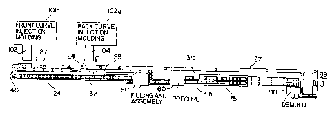
As illustrated in Figures 1 and 2 injection
molds #1 and #2, shown at steps 101 and 102 in the flow
diagram of Figure 1, mold respectively front curve and
back curve lens mold parts or sections, in matched sets;
they may be located in tandem as shown in Figure 2 or to
shorten exposure to the atmosphere still further, they may
be located in a common plane intersecting a bifurcated
transport line, even perpendicularly oriented thereto in
the same plane._
Robotic means 103,104 are provided adjacent the
mold registry and engagement station for receiving concave
and convex lens molds respectively and transferring said
mold part to a low oxygen environment at a high production
cycle rate, as noted at step 105.
In the course of or following complete degassing
of the lens mold sections as indicated at 106 in Figure 1,
the pallets containing concave and convex lens mold
sections are ordered into interleaved relation and
degassed on enclosed infeed conveyor such that automated
equipment may effect their operative interengagement into
molding relation.
The sequencing conveyor 32 including the
interleaving station 40 is enclosed and pressurized over
its entire length with_-.an inert gas, conveniently
-
-22- _- 2151353
'-.
nitrogen. The amount of nitrogen is not critical, it
1 being suitable to use just enough nitrogen pressure to
effectively exclude the atmosphere under the operating
conditions experienced. In the nitrogen tunnel
surrounding sequencing conveyor 32 the freshly prepared
lens mold blanks are degassed as indicated at step 106 in
Figure 1.
The concave lens molds are filled with the
reactive monomer composition at step 107 and the concave
and convex lens molds are placed into registry and urged
into complementary molding relation. The filling and
assembly zone 50 surrounds a portion of the conveying or
transport means 32, which delivers to the zone pallets of
concave and convex lens mold sections, respectively, and
at the terminus of the zone carries pallets of paired and
filled molds to the precure zone. The filling and
assembly zone illustrated in Figure 2 at 50 is defined by
a geometrically appropriate, transparent enclosure,
generally of rectangular cross-section, formed of any
suitable thermoplastic or metal and thermoplastic.
construction.
As illustrated at 107 in Figure 1, the concave
lens mold sections are filled with degassed monomer
composition from step 108, and then transported to an
assembly module having a vacuum chamber formed
intermittently within the nitrogen tunnel in which filled
concave lens molds are engaged with convex mold sections
in vertical alignment and in mating relation, such that
the reactive monomer composition is trapped between the
optical surfaces of the respective mold sections and at
least partially sealed by the engagement of the parting
edge formed peripherally in each of the lens mold
sections. The vacuum is released and the mated mold is
passed through nitrogen to the precure station, an
integral part=of the nitrogen tunnel.
-
2151353
-23- _
As will hereinafter be explained in detail, the
1 vacuum chamber is formed upon and about a single pallet by
the periodic reciprocable motion of apparatus also
comprising means for alignment of the seating of the
convex mold sections upon the concave mold sections so
their axes of rotation are collinear and their respective
flanges are parallel. Upon sealing engagement with the
pallet the thus formed chamber is evacuated in order to
ensure that no gas bubbles are entrapped between and upon
the respective optical molding surfaces. The degree of
iQ vacuum is selected for the purpose of speeding=the
assembly of mold parts and removing any gas bubbles at the
monomer/mold interface that might otherwise be entrapped
in the course of closure between the complementary mold
sections.
Following assembly of the mold parts, the
incipient lens monomer is precured at step 109 in the
precure module 60 of the present invention. The process
of the precure involves clamping the mold halves in
registration and then precur-ing= the monomer --or monomer ,
mixture to a gel like state.
Following precure, the polymerization of the
monomer or monomer mixture is completed in curing tunnel
75 as indicated at step 110 as will be hereinafter
explained in detail.
Following complete polymerization, the lenses
are demolded by heating the back curve mold and then
prying from the front curve and mold in the demold
assembly 90 as indicated at step 111. Finally, the lens
is hydrated, inspected and packaged as indicated at step
112.
Thus, the invention permits the generation of
high optical quality soft contact lenses in volume and at
high speed, with a low defect count.
-24- - 21513 5 3
Referring to Figures 1 and 2, the first and
1 second injection molds 101'(a) and 102(a) are continuously
cycled to periodically produce (generally, from 3 to 12
seconds, and preferably, about 6 seconds) sets of concave
and convex lens mold parts or sections which are collected
from molds at the end of each cycle. In the geometric
configuration obtaining, (and 'preferred for better
manipulative exchange) the mold upon opening for demolding
present the finished lens mold parts in or close to the
vertical plane, generally -5 to 10 from the vertical. As
illustrated in Figure 2 and noted at step 105 in Figure 1,
a plurality of fingers of the articulated robotic means
103, 104 gently engage and receive the set of molds and
while maintaining same in essentially the same spatial
relation, rotates them from a plane generally
perpendicular to the transport line through 90 to a
parallel plane above the transport means while
simultaneously or sequentially rotating toward and
engaging the horizontal plane of the transport line, and
releases the mold parts into registry with carrier pallets
on conveyor means indicated generally at 27,29 in
Figure 2.
The robotic transporting assemblies generally
depicted at 103,104 in Figure 2, deposit the back curve
r
mold parts directly on a production line pallet that has
been momentarily paused by a clamping means.
As will be hereinafter explained with reference
to Figure 8(a), the front curve mold parts or halves are
removed form the injection mold 10(a) in an inverted
orientation to avoid any possible contact with the optical
surface of the mold half. The front curve halves are then
inverted by another robotic transfer device and deposited
on a stationary pallet therebelow.
2151353
-25- -
After receiving the sets of mold parts, the
1 pallets are advanced by the belt conveyors 27,29, in the
direction indicated by the arrows in Figure 2 into a low
oxygen environment, generally indicated by housing means
24. Housing means 24 is pressurized with N2 as indicated,
and may optionally be equipped with air lock means at each
entry and egress point of the low oxygen environment.
Figures 3 and 3(a) illustrate respectively top
elevational and side views of one embodiment of a first or
front mold half 10 useful in the production of a contact
lens by the polymerization of a monomer or monomer mixture
in a mold assembly composed of two complementary front and
ba3e mold halves. The front mold half 10 is preferably
formed of polystyrene but could be any suitable
thermoplastic polymer such as mentioned hereinabove which
is sufficiently transparent to ultraviolet or visible
light to allow irradiation therethrough with light to
promote the subsequent polymerization of a soft contact
lens. Alternatively, other forms of radiant energy could
be used providing the front mold half is transparent --to
that form of energy. A suitable thermoplastic such as
polystyrene also has other desirable qualities such as
being moldable to surfaces of optical quality at
relatively low temperatures, having excellent flow
characteristics and remaining amorphous during molding,
not crystallizing, and having minimal shrinkage during
cooling.
The front mold half 10 defines a central curved
section with an optical quality concave surface 15, which
has a circular circumferential parting edge 14 extending
therearound. The parting edge 14, shown in enlarged
detail in Figure 3(b), is desirable to form a sharp and
uniform plastic radius parting line (edge) for the
subsequently molded soft contact lens. A generally
parallel convex surface 16 is spaced from the concave
-26- -2151353
surface 15, and an annular essentially uniplanar flange 18
1 is formed extending radially outwardly from the surfaces
15 and 16 in a plane normal (perpendicular) to the axis
(of rotation) of the concave surface 15. The concave
surface 15 has the dimensions of the front curve (power
curve) of a contact lens to be produced by the front mold
half, and is sufficiently smooth such that the surface of
a contact lens formed by polymerization of a polymerizable
composition in contact with the surface is of optically
acceptable quality. The front mold half is designed with
a thinness (typically 0.8 mm) and rigidity effective to
transmit heat therethrough rapidly and to withstand prying
forces applied to separate the mold half from the mold
assembly during demolding.
The front mold half or curve thickness was
reduced from 1.5 mm in prior designs to 0.8 mm. This has
a direct impact on cycle time reduction.
Figures 4 and 4(a) illustrate respectively top
elevational and side views of one embodiment of a second,
or back curve mold half 30. The back curve mold half is
designed with--all- of =the same design considerations
mentioned hereinabove with respect to the front curve mold
half 10.
The back curve mold half 30 is also preferably
formed of polystyrene but could be any suitable
thermoplastic such as those mentioned hereinabove which is
transparent to visible or ultraviolet light. The back
curve mold half 30 defines a central curved section with
an optical quality convex surface 33, a generally parallel
concave surface 34 spaced from the convex surface 33, and
an annular essentially uniplanar flange 36 formed
extending radially outwardly from the surfaces 33 and 34
in a plane normal to the axis (of rotation) of concave
surface 34. The convex surface 33 has the dimensions of
the rear curve (which rests upon the cornea of the eye) of
-27- _ 2151353
a contact lens to be produced by the base mold half, and
1 is sufficiently smooth such that the surface of a contact
lens formed by polymerization of a polymerizable
composition in contact with the surface is of optically
acceptable quality. The base mold half is designed with
a thinness (typically 0.6 mm) to transmit heat
therethrough rapidly and rigidity effective to withstand
prying forces applied to separate the mold half from the
mold assembly during demolding.
The base curve is designed with a base curve sag
of 5.6 mm (see Figure 4(a) for the predetermined sag,
dimension "Y"). The base curve sag and thickness of
0.6 mm serves two purposes:
1. The base curve sag results in a gap of
1.5 mm - 3.0 mm between the assembled base curve and front
curve, which assists in mechanically removing the base
curve from the front curve matrix after polymerization
which forms a contact lens.
2. With a part thickness on the order of
0.6 mm, the base _curve. reduces the occurrence of,weld..
lines on the distal side of the flange (where two melt
flows converge) which could detrimentally cause a fracture
line on the base curve.
The mold halves 10,30 define generally
triangular tabs 26,37 integral with the flange which
project from one side of the flange. The tab 37 extends
to the injection hot tip which supplies molten
thermoplastic to the mold, and also defines therein an
angled (e.g., 45 ) web sections 22,38 for smoothing the
flow of the polymer wave front and thus to avoid jetting,
sink marks, weld lines and other undesirable flows which
would impair the optical quality of the mold half. The
mold halves 10,30 also define a small circular projections
25,35 which serve as traps in the molding process to
2151353
-28- -
immobilize small plugs of colder polymers that may form at
1 the injection hot tip between cycles.
The monomer and monomer mixtures to which this
process may be directed include copolymers based on 2-
hydroxyethylmethacrylate ("HEMA") and one or more
comonomers such as 2-hydroxyethyl acrylate, methyl
acrylate, methyl methacrylate, vinyl pyrrolidone, N-vinyl
acrylamide, hydroxypropyl methacrylate, isobutyl
methacrylate, styrene, ethoxyethyl methacrylate, methoxy
triethyleneglycol methacrylate, glycidyl methacrylate,
diacetone acrylamide, vinyl acetate, acrylamide,
hydroxytrimethylene acrylate, methoxyethyl methacrylate,
acrylic acid, methacryl acid, glyceryl methacrylate, and
dimethylamino ethyl acrylate.
Preferred polymerizable compositions are
disclosed in U.S. Patent No. 4,495,313 to Larsen, U.S.
Patent No. 5,039,459 to Larsen et al. and U.S. Patent No.
4,680,336 to Larsen et al., which include anhydrous
mixtures of a polymerizable hydrophilic hydroxy ester of
acrylic acid or methacrylic acid and a polyhydric alcohol,
and a water displaceable ester of boric acid and a
polyhydroxyl compound having preferably at least 3
hydroxyl groups. Polymerization of such compositions,
followed by displacement of the boric acid ester with
water, yields a hydrophilic contact lens. The mold
assembly of the present invention described herein may be
used to make hydrophobic or rigid contact lenses, but the
manufacture of hydrophilic lenses is preferred.
The polymerizable compositions preferably
contain a small amount of a cross-linking agent, usually
from 0.05 to 2% and most frequently from 0.05 to 1.0%, of
a diester or triester. Examples of representative cross
linking agents include: ethylene glycol diacrylate,
ethylene glycol dimethacrylate, 1,2-butylene
dimethacrylate, 1,3-butylene di-methacrylate, 1,4-butylene
'-- -29- 2151353
propylene glycol diacrylate, propylene
1 glycol dimethacrylate, diethylglycol dimethacrylate,
dipropylene glycol dimethacrylate, diethylene glycol
diacrylate, dipropylene glycol diacrylate, glycerine
trimethacrylate, trimethylol propane triacrylate,
trimethylol propane trimethacrylate, and the like.
Typical cross-linking agents usually, but not necessarily,
have at least two ethylenically unsaturated double bonds.
The polymerizable compositions generally also
include a catalyst, usually from about 0.05 to 1% of a
free radical catalyst. Typical examples of such catalysts
include lauroyl peroxide, benzoyl peroxide, isopropyl
percarbonate, azobisisobutyronitrile and known redox
systems such as the ammonium persulfate-sodium
metabisulfite combination and the like. Irradiation by
visible light, ultraviolet light, electron beam or a
radioactive source may also be employed to catalyze the
polymerization reaction, optionally with the addition of
a polymerization initiator. Representative initiators
include camphorquinone, ethyl-4-(N,-N-dimethyl-
amino)benzoate, and 4-(2-hydroxyethoxy_)phenyl-2--hydroxyl-
2-propyl ketone.
Polymerization of the monomer or monomer mixture
in the mold assembly is preferably carried out by exposing
the composition to polymerization initiating conditions.
The preferred technique is to include in the composition,
initiators which work upon exposure to ultraviolet
radiation; and exposing the composition to ultraviolet
radiation of an intensity and duration effective to
initiate polymerization and to allow it to proceed. For
this reason, the mold halves are preferably transparent to
ultraviolet radiation. After the precure step, the
monomer is again exposed to ultraviolet radiation in a
cure step in which the polymerization is permitted to
proceed to completi-on=. The required duration of the
2151353
.._, -30- -
remainder of the reaction can readily be ascertained
1 experimentally for any polymerizable composition.
As indicated at step 108 in Figure 1, the
monomer or monomer mixture is degassed prior to the
/ filling of the front curve mold half in order to remove
dissolved gases. 02 is removed because of its deleterious
effect on polymerization as noted above. Other gases,
including N2, are removed to avoid the formation of gas
bubbles when the monomer is expelled from the relatively
high pressure of the pump line which supplies the fill
nozzle, to encounter the atmospheric or subatmospheric N2
pressure of the filling and assembly chambers.
As illustrated in Figure 9 the polymerizable
monomer or monomer mixture is provided in containers 400,
typically 15 liters in volume. The container is connected
to the monomer degassing system by means of line 412.
Suction is developed by pump 414 to draw the monomer from
the drum 400, through line 412, to pump 414, and out the
pump discharge 416. While going through discharge line
416, the monomer passes through filter 418 in order to
remove any extraneous particulate contaminants that may be
present in the monomer.
The monomer is then provided to the inlet 420 of
the degas unit 422. Within the degas unit, the monomer is
divided among a plurality of tubes 424, and then
recombined into a degas unit discharge 426. The degas
unit is operated under a low ambient pressure, typically
around 4 torr which is provided by vacuum pump 428. This
vacuum pump is attached to the degas unit 422 by line 430
and discharges the excess air from the degas unit by way
of line 432. The tubing members 424 are formed preferably
of a gas permeable tubing such as STHT tubing produced by
Sanitec, Inc. of Andover, New Jersey from Q74780 Medical
Grade Silicon Rubber manufactured by Dow Corning of
Midland-, Michigan. While two tubes are illustrated in
2151353
~-- -31- -
Figure 9, it is understood that a plurality of tubes,
1 typically 10 tubes are provided for the degas unit 422.
After the monomer exit the degas unit 422 by
discharge line 426, it passes through an oxygen monitor
434. This monitor measures the residual oxygen within the
monomer to insure that the degas unit is functioning
properly. If the oxygen content of the monomer is
indicated as being to high, operation of the production
line can be halted until the problem is corrected in order
to avoid the production of defective lenses.
Once oxygen monitor 434 has determined that the
oxygen content of the monomer is sufficiently low, the
monomer passes through line 436 into manifold 438. The
manifold is used as a common source to supply a plurality
of precision dose pumps 440 used to fill the individual
contact lens mold at the monomer filling and assembly
dosing station 50. The pumps 440 used to pump the
processed monomer delivered to manifold 438 are pumps made
by the IVEK Corporation, North Springfield, Vermont.
These pumps provide precision doses of degassed--monomer to
the mold cavities 15 via nozzles 242. A return line 442
keep the monomer of the front curves 10 circulating when
not pumped by pumps 440.
A top view of a production line pallet 12 for
carrying production lens mold halves is shown illustrated
in Figure 7(a), with a side view illustrated in Figure
7(b) and a bottom view illustrated in Figure 7(c). It
should be understood that all pallets 12 are
interchangeable in that they may accommodate either front
curve or back curve contact lens mold halves. In the
preferred embodiment shown in Figure 7(a), the production
line pallet 12 is formed of aluminum and may be 60 mm in
width and 120 mm in length. In another embodiment, the
pallet 12 may be formed of stainless steel and may be
- 80 mm in width and 160 mm in length.
-32_ _-2151353
..,~
Each pallet 12 contains a plurality of recesses
1 for receiving a respective contact lens mold assembly 39
comprising a complimentary front 10 and back 30 curve mold
halves which define the shape of the final desired lens.
One such mold assembly 39 is shown seated within a recess
130(b) of the pallet in Figure 5. The contact lenses are
formed by placing an amount of polymerizable monomer or
monomer mixture, generally on the order of about 60 N1, in
each front curve (concave) mold half 10 seated within a
pallet recess 130(b) at the filling and mold assembly
apparatus 50. The desired amount depends on the
dimensions (i.e., the diameter and thickness) of the
desired lens, taking into account the generation of by-
products upon polymerization and the exchange of water for
those by-products and diluent, if any, following
polymerization. Then, the back curve (convex) mold half
30 is placed onto the polymerizable composition 11 with
the first and second mold halves aligned so that their
axes of rotation are collinear and the respective flanges
18,36 are parallel. The mold halves_are,_transported in an
annular recess 130(a) which receives and supports the
annular flange 18 of the front curve mold half. In
addition to the recesses 130(a) and (b), the pallets 12
also have a plurality of oriented recesses 130(c) which
receive the triangular tab portions 26 of the seated front
curve mold half 10 to provide a predefined angular
position thereof. The recesses 130(a) are designed to
prevent movement of the normally seated mold half within
each recess up to within +/- 0.1 mm. The triangular tab
37 of the second or back curve mold half 30 overlies front
curve tab 26 to enable a collinear axis of rotation with
respect to the two mold halves, if desired.
As illustrated in Figures 7(a)-7(c), pallet 12
of the present invention is designed to ensure that a
tight vacuum seal may be created with the surface of the
CA 02151353 2006-03-06
-33-
pallet during the monomer deposition and contact lens mold
1 assembly phases of the production line facility. As will
be explained in further detail below, blind locating
bushings 129(a) and 129(b) are located at opposite ends of
the pallet 12 to enable precise positioning of the pallet
within the various assemblies of the production line.
These locating bushings enable a precise registration of
the pallet throughout the various assemblies of the
contact lens production facility, and, thereby assist in
the alignment of a tight vacuum seal to be created at the
peripheral upper surface 140 of the pallet prior to
assembling the mold halves. As shown in Figure 7(a),
proximate the center of each pallet 12(a) is a unique bar
code identifier 135 for handling, tracking, and quality
control purposes.
As further shown in Figures 7(b) and 7(c), the
outer peripheral edges of the pallet 12 define a notch or
indentation 28(a),(b) for engaging a complementary guide
rail or shoulder for enabling precise registration of the
pallet at the demolding apparatus, as wil-1 be explained in
greater detail below. Additionally, the -pallet 12
includes blind holes 128(a)"and 128(b) wherein an optic
bore scope or similar viewing device may be inserted to
enable real time viewing of the contact lens production
process at the surface of the pallet.
Figure 8(a) illustrates in detail the robotic
transporting assemblies 103,104 of Figure 2 for rapidly
transporting respective front curve and back curve mold
portions from respective injection molds 101(a) and 102(a)
to respective pallets 12(a) and 12(b).
35
CA 02151353 2006-03-06
-34-
1
Generally, robotic transporting assembly 103 is
provided with a first robotic assembly 715 for removing
front curve lens molds from injection mold assembly
101(a), and transporting the mold to a first location;
assembly 717 is provided for receiving the front curve
lens molds from assembly 715 and transporting the molds
from the first location to a second location, and robotic
assembly 716 is provided for receiving the front curve
lens molds from assembly 717 and transporting those molds
-15 from the second location to an inverting hand 738(a) of
inverting assembly 738 that inverts the orientation of the
front curve molds carried by the robot 716. This
inversion is necessary because the robotic assembly 716 is
handling the front curve molds by their non-optical
(convex) side. and the front curve molds must therefore be
inverted to enable the non-optical surface of each mold to
be placed in the pallet 12(a) (under inverting hand
738(a)) that has been momentarily paused to receive the
front curve lens molds.
The robotic transfer assemblies 103,104 are more
fully described with respect to Figure 8(a) as follows.
Support subassemblies 716(a),(b) of robotic assembly
715(a),(b) are connected to hands 714(a),(b) to support
the hands and to move the hands between molds
101(a),102(a) and the first location, which preferably is
directly above transfer platforms 717(a),(b) of the second
robotic assembly 717,728. Preferably, support frames
724(a),(b) are located adjacent molds 101(a),102(a) and
support subassemblies 716(a),(b) are supported on frame
2151353
-35-
724(a),(b) for sliding movement toward and away from molds
1 101(a),102(a). As the assemblies 15(a),(b) slide along
frames 724(a),(b), hands 714(a),(b) move with the
assemblies toward and away from molds 101(a),102(a).
More specifically, arms 716(a),(b) are slidably
mounted on frames 724(a),(b), to extend outward from these
frames, and are pivotally mounted on assemblies 715(a),(b)
while hands 714(a),(b) are rigidly connected to the
outward ends of arms 716(a),(b) for movement therewith.
With this arrangement, arms 716(a),(b) carry hands
714(a),(b) toward and away from molds 101(a),102(a), while
allowing the hands to pivot between a substantially
vertical orientation, as shown in Figure 8(a), and a
substantially horizontal orientation, to deposit the mold
parts on carriers 717(a),(b).
Preferably, arms 716(a),(b) are high speed, low
mass assemblies, and are able to move hands 714(a),(b)
into molds 101(a),102(a), and remove articles therefrom,
at a rate of once every 3 to 12 seconds and preferably
every 6 seconds. Also, preferably the arm is constructed
from a high strength, low mass material such as material
sold under the trademark Kevlar.
Each of the hands 714(a),(b) are equipped with
a plurality of hollow cylindrical bellows, two of which
are illustrated on each hand at 720(a),(b). The bellows
are connected to a vacuum manifold and vacuum line for
engaging and securing the mold parts thereto as they are
ejected.
As previously mentioned, second robotic
assemblies 717,728 receive articles from first robotic
assemblies 715(a),(b), at the first location, and
transport those articles to the second location; and,
generally, second robotic assemblies 717,728 include
support frames 740(a),(b), platforms 717(a),(b), and tread
covered support lines 756(a),(b). Support frames
-36= 2151353
740(a),(b) have the general shape of an elongated cube or
1 box and extend from a position located directly below the
above-mentioned first location to a position directly
below the above-mentioned second location. The top
portion of frames 740(a),(b) form channels 746(a),(b) that
longitudinally extend between the transverse ends of the
support frame.
Transfer platforms 717(a),(b) are provided to
receive articles from first assembly 715(a),715(b),
specifically hands 714(a),(b) thereof, and to carry those
articles on support frames 740(a),(b) for sliding or
rolling movement therealong.
The upper section of transfer platforms
717(a),(b) include or form a multitude of receptacles 766
for receiving and holding mold halves received from hand
members 714(a),(b). Preferably, receptacles 766 on
transfer platforms 717(a),(b) are located so that when
hands 714 of assemblies 15(a),15(b) are positioned
directly above transfer platforms 742(a),(b), each of the
bellows 720 of. hands 714(a),(b) =are -aligned -with a
respective one of the receptacles 726 of platforms
717(a),(b).
A moving means is provided to move the transfer
platforms 717(a),(b) along frames 740(a),(b), and
preferably the moving means includes a ball screw and
motor mounted within support frames 740(a),(b) and coupled
to the platforms 717(a),(b) by brackets. Treads
756(a),(b) protect and route the electrical vacuum and
pneumatic support for the transfer platforms 717(a),(b).
The tread protectors 756(a),(b) are located adjacent
support frames 740(a),(b) and are supported for movement
between extended and retracted positions.
A pair of third robotic assemblies 716,726 are
illustrated and are provided to receive articles from
second assemblies 717,728, to releasably hold those
-
2151353
-37- -
articles and to carry the articles to a third location.
1 Support column 766(a),(b) supports robotic assemblies
716,726 for movement between the second and third
locations. More specifically, support columns 766(a),(b)
are supported and extends upward between the above-
mentioned second and third locations. First arms
770(a),(b) of robotic assemblies 716,726 are supported by
support columns 766(a),(b) for pivotal movement, and this
first arm extends outward from the support column; and
second arms 772(a),(b) are supported by first arms
770(a),(b) for pivotal movement on one end of arms
772(a),(b) and extend outward therefrom.
Preferably, a third vertical arm is provided for
each robotic assembly that is extensible, and this arm is
extended and retracted to lower and raise hands 776(a),(b)
indicated by dotted lines in Figure 8(a). Any suitable
means may be used to extend and to retract the third arm;
and, for instance, a hydraulic cylinder or screw motor may
be mounted in the robotic assembly, with hands 776(a),(b)
connected to a lower end of the hydraulic cylinder or_
screw motor.
Hands 776(a),(b) are provided for receiving and
releasably holding the mold halves, and preferably these
hands also include a plurality of bellows for gripping the
mold halves.
In the operation of the robotic assemblies
716,726, arms 770(a),(b) are pivoted about column
766(a),(b) and arms 772(a),(b) are pivoted on arms
770(a),(b) to the position shown in Figure 8(a), where the
arms and hands 776(a),(b) are directly above the second
extended position of transfer platforms 717(a),(b). Hands
776(a),(b) are then lowered toward or into engagement with
transfer platforms 717(a),(b) and the mold halves are
transferred from transfer platforms 717(a),(b) to hands
776(a),(b) and-the hands are then raised, clearing the
-38- 2151353
hands from the transfer platforms 717(a),(b). Arms
1 770(a),(b) are then pivoted about columns 766(a),(b),
clockwise as viewed in Figure 8(a), and, simultaneously,
arms 772(a),(b) are pivoted on arms 770(a),(b),
counterclockwise as viewed in Figure 8(a), until hands
716(a),(b) are located directly above the position at
which the mold halves are to be deposited. The vertical
arms mounted on the second arms 772(a),(b) are then
extended to lower hands 776(a),(b), and the mold halves
may be transferred from hand 776(a) to pallet 738(a) of
inverter 738 or from hand 776(b) directly on a pallet
12(b) carried on conveyor 29.
To elaborate, when robotic transport assembly
103 carries mold halves, preferably all physical contact
between the elements of robotic assembly 103 and the mold
half is on the sides of the mold that are opposite the
optical surfaces of those mold sections. In this way,
there is no physical contact between any part of robotic
assembly 103 and the surfaces of the mold that directly
engage the hydrophilic material used to'form the contact
20lens molded between the mold halves. Thus, when assembly
103 carries mold half away from injection mold 101(a), the
mold half is inverted; while when assembly 104 carries a
mold half away from injection mold 102(a), the mold is in
its position and ready for deposit on a carrier pallet.
Thus, when robotic assembly 103 carries mold halves away
from injection mold 101(a), the mold half is not in the
proper orientation for transfer to pallet 12(a), and the
mold half must be inverted in order to orient it properly
for transfer to pallet 12(a). The preferred embodiment of
inverter assembly 738 is provided to do this.
As mentioned above, inverter assembly 738
includes hand 738(a) and support subassembly 786.
Preferably, hand 738(a) includes a base and bellows to
r-f:ceive mold halves from the third robotic assembly 716,
2151353
-39-
specifically hands 776(a) thereof, and to hold those
articles while they are inverted for transfer to pallet
12(a).
Support subassembly 786 is provided to move hand
738(a) of assembly 738 between third and fourth locations,
and in the preferred embodiment, support subassembly 786
is used to pivot and to reciprocate hand 738(a). With the
embodiment of subassembly 738 illustrated in the drawings,
arm 794 extends outward from subassembly 786, and hand
738(a) is rigidly connected to an outward or second end of
arm 794 for pivotal movement therewith. Preferably, hand
738(a) is pivoted substantially 1800, from a position in
which the bellows on the hand extend directly upward to a
position in which these bellows extend directly downward.
After receipt of the mold halves from hand 776(a), the
inverter assembly 738 reciprocates hand 738(a) downwardly
and then releases the mold halves onto a pallet 12(a) that
has been temporarily paused by clamping means 19(a),19(b)
as will hereinafter be explained.
Each of the pallets is momentarily paused on
conveyor belts 27,29 at the time of transfer of the molds.
In the preferred embodiment shown in Figure 8(a), and in
elevation in Figure 6, a clamping mechanism 19 comprising
a pair of clamping jaws 19(a),(b) are located at opposite
sides of the conveyor 27 to timely clamp an empty pallet
12(a) and halt the motion so that the front curve mold
halves may be positioned on the pallet by inverting head
738(a), while a pair of clamping jaws 20(a),(b) are
located to timely clamp an empty pallet 12(b) to halt its
motion on conveyor 29 while the back curve mold halves are
positioned on the pallet by robot assembly 726.
The front and back curve mold halves are also
transferred from their respective injection mold
assemblies 101(a),102(a) to a low oxygen, and preferably,
a nitrogen environment maintained around portions of the
-40- _ 2151353
front curve conveyor 27, back curve conveyor 29, and a
1 sequencing conveyor 32 by housing 24. This inert
environment is accomplished by enclosing each conveyor in
an atmosphere of pressurized nitrogen gas. As will be
explained below, the handling of the pallets and the
contact lens mold assemblies throughout the various
stations of the production line facility are conducted in
an inert, and preferably a nitrogen gas to provide a low
oxygen environment for all of the component pars prior to
polymerization. While it is possible to enclose injection
mold assemblies 101(a),102(a) and robotic transport
assemblies 103,104 within a nitrogen enclosure, it has
been found that the use of the high speed robotic
assemblies illustrated in Figure 8(a), a transfer can be
accomplished in under 15 seconds, with a mold cycle time
of 6 seconds. The 15 second exposure to atmospheric
oxygen requires only a 3 minute residence time under N2 to
degas 02 adsorbed during the 15 seconds. A 3 minute buffer
on sequencing conveyor 32 also ensures an adequate supply
of molds for the assembly line. Opening the injection
mold devices 101(a),102(a) to atmospheric cooling
alleviates substantial cooling problems that would
otherwise be encountered by running the molding machines
in an enclosed environment.
The operation of the clamping mechanisms 19 and
20 will now be described in view of Figure 6. It should
be mentioned that the operation of all clamping mechanisms
hereinafter disclosed, is essentially the same as the
following description of the preferred embodiment.
Specifically, the clamping mechanism 19 consists of one or
more pneumatic cylinders 21 that operates to push lower
ends 44(a),(b) of clamping jaws 19(a),(b) so the jaws
pivot about associated clamping shafts 42(a),(b) to close
in and enable respective fixed clamping blocks 19(c),(d)
to grip pallet 12(a) (shown in phantom lines in Figure 6)
r-- -41- 2151353
that is positioned in alignment with the jaws 19(a),(b).
i As illustrated in the Figure 6, the clamping blocks
19(c),(d) of clamping jaws 19(a),(b) are located just
above and at opposite sides of the conveyor 27 while the
pneumatic cylinder 21 is mounted below the conveyor 27.
To transport the pallets, each supply conveyor
27,29 comprises a drive means in the form of a motor
driven belts, one of which is illustrated in cross-section
in Figure 6(a) as 43(a), which are strong enough to
support pallets 12(a),(b) supplied to the sequencing
apparatus 40. As illustrated in Figures 7(b) and (c), a
raised underside section 138 of each pallet 12(a),(b) may
be coated with Nedox or Tufram so to enable sliding of
the pallet when being held above a moving belt by clamping
jaws 19,20 or pushed along slide plates at certain
processing locations of the plant.
The pallet, conveyors 27,29 and 32 include a
drive means for each of the motor driven belts. The motor
drive means to conveyor 32 enables the transport of thirty
or more paired sets of -pallets 12(a),12(b) carrying
respective front and back curve lens mold portions to be
smoothly and uniformly transported at a preferred rate of
approximately 30 mm/sec until they are assembled for
processing at the filling/mold assembly apparatus 50. In
a similar fashion, suitable motors drive respective
conveyor belts 43(a),43(b) carrying the respective pallets
12(a),12(b) so that they are smoothly and uniformly
transported at a preferred rate of approximately 75 mm/sec
until their motion is terminated at the ends of each
conveyor for sequencing as will be explained in further
detail below. Additionally, idler rollers and tensioner
roller may be provided for adjusting the tension of the
belts of conveyors 27,29 and 32.
Figure 6 illustrates a cross-sectional, front
view of a conveyor assembly 27 shown carrying a pallet
-42- 2151353
12(a) on conveyor belt 43(a). It is understood that the
1 view of Figure 6 may apply to any of the other above-
described conveyors 29 and 32 carrying pallets.
Figures 8(a) illustrates the sequencing
apparatus 40 (demarked by dotted lines in Figure 8(a)) of
pallet system comprising a double cross pusher which
positions a pallet 12(a) from conveyor 27 (containing
front curve contact lens mold portions) next to a pallet
12(b) from supply conveyor 29 (containing back curve
contact lens mold portions) for conveyance along the
sequencing conveyor 32. The sequencing apparatus 40 is
located at the ends of each supply conveyor 27, 29 and
comprises a first arm 141 and second arm 142 for
simultaneously pushing pallets from respective supply
conveyors 27 and 29 along track 143 for entry into the
main sequencing conveyor 32. As illustrated in Figure
8(a), the first arm 141 and second arm 142 are mounted in
parallel on mounting means 145 that is slidable along
track 147 in both directions as indicated by the double
arrow in Figure 8(a). A lifting means, which may be
pneumatically operated, is provided for raising and
lowering the first and second arms 141,142 in a vertical
direction above the plane of a horizontally positioned
pallet, as will be explained in further detail below.
While the arms 141,142 are in a raised position, the
mounting means 145 remains slidable along track 147 so
that the first and second arms may be retracted while in
their raised position and subsequently lowered after
reaching their original positions.
In a first step of the sequencing process, the
forward motion of a pallet 12(a) from conveyor 27 is
terminated at a first position "A", just forward of the
first arm 141, as shown in Figure 8(a). Forward motion of
the pallet 12(a) is terminated by a pair of upstream
clamping jaws 146(a),(b), that, in a timed fashion, open
-
_43_21513 5 3
and close to let one pallet align with the first pusher
1 arm 141 of the double pusher. When jaws 146(a),(b) are
closed, forward motion of the pallet is terminated and a
plurality of pallets will accumulate behind the clamped
pallet. At the appropriate time, one pallet may be
released by opening the clamping jaws 146(a),(b) so that
the forward motion of the accumulating pallets on conveyor
27 will push the first lead pallet to a second position
indicated as "B" in Figure 8(a), also in alignment with
the first pusher arm 141. The jaws 146(a),(b) may be
immediately closed to clamp the next of the accumulated
pallets to prevent their forward motion. The opening and
closing of the clamping jaws 146(a),(b) may be
appropriately timed to enable pallets to be sequentially
input to the pusher in an orderly fashion.
After appropriate sensing, and, as controlled by
a computer or a programmable logic controller, the arms
141,142 of double cross pusher 40 are caused to slide
along track 147 in the first direction from S to S'
.: - indicated by the doub-l:e headed arrow S = S' - in -Figure =8 (a)
so that first arm 141 pushes pallet 12(a) to a second
position that is located just forward of second arm 142
position and indicated by arrow "C" in Figure 8(a). It is
understood that during initialization of the sequencer,
the second arm 142 did not push a pallet since none were
positioned for movement in front of second arm. The
lifting means is then commanded to raise the first and
second arms 141,142 so that the mounting means and the
arms may be retracted along track 147 and subsequently
lowered back at their original position as shown in Figure
8(a).
The following description demarcates where
steady state sequencing operations begin. As shown in
Figure 8(a), after retracting first and second arms
141,142 to their original positior-, or, preferably, while
~.. -44- 21513 5 3
the arms are in their raised position while being
1 retracted, a new pallet 12(a) carrying front curve lens
mold portions from conveyor 27 is positioned at the
vacated first position (indicated by arrow "A") in the
manner described above. Simultaneously therewith, the
forward motion of a pallet 12(b) carrying back curve
contact lens mold portions from back curve supply conveyor
29 is terminated at a position "D" as indicated in Figure
8(a). The process for aligning a pallet 12(b) carrying
back curve lens mold portions at position B is essentially
similar as described above with respect to pallet 12(a).
In a timed manner, clamping jaws 149(a),(b) close to clamp
pallet 12(b), while the other pallets on conveyor 29
accumulate behind the clamped pallet. The jaws 149(a),(b)
are subsequently opened to release the pallet so that the
motion of the conveyor 29 pushes the pallet 12(b) in
alignment with the second pusher arm 142. The jaws
149(a),(b) are immediately closed to clamp the next of the
accumulated pallets to prevent its forward motion. Pallet
12(b) carrying.back curve contact lens mold portions is
now positioned at "D", immediately adjacent the previously
positioned pallet 12(a) from the initial step, situated at
position "C", with both in alignment with the second arm
142. After appropriate sensing, the arms 141,142 of the
double cross pusher 40 are again caused to slide along
track 147 from their original position in the direction
indicated by the double headed arrow so that first arm 141
pushes a pallet 12(a) to the second position ("C") and the
second arm 142 pushes the pair of pallets 12(a),12(b) from
second position "C and D" to a third position indicated by
"E" in Figure 8(a). Finally, the pusher arms 141,142 are
raised so that the mounting means 145 and the arms may be
retracted along track 147 and lowered at their original
position. While the first and second arms 141,142 are
being retracted, a new set of pallets are being loaded at
-452151353
their respective positions. Specifically, a pallet 12(a)
1 is loaded at position indicated as "B" (Figure 8(b)) and
a pallet 12(b) is loaded at position indicated as "D"
adjacent the previously positioned pallet 12(a) and the
sequence is repeated.
While the new set of pallets are being loaded at
their respective positions, a third pusher arm 144
operable by pneumatic driving means 148 is activated to
push the adjacently situated pair of pallets 12(a),12(b)
in the direction indicated by arrow "F" in Figure 8(a),
for engagement with the drive belt 44(a) of sequencing
conveyor 32. In steady state operation, the sequence of
events described above is repeated so that pairs of
pallets 12(a),12(b) are sequentially transported along
sequencing conveyor 32 to the filling and mold assembly
stations of the contact lens production facility.
The paired sets of pallets 12(a),12(b) carrying
respective front curve and back curve lens molds reach a
second sequencing apparatus 52 (illustrated in Figure
8(b)) where their forward motion is diverted for input to
the filling apparatus 50.
Figure 8(b), which is a continuation of Figure
8(a), illustrates the precision pallet handling apparatus
55 for transferring pallets from sequencing conveyor 32 to
the filling apparatus 50. Specifically, the motion of
each pallet 12(a),(b) carrying respective lens mold halves
is terminated by a pair of upstream clamping jaws 153(a)
and 153(b), in the manner as described above, at position
indicated as "C" in front of pusher 154(a) of ram 154.
When the motion of the first pallet is halted, the
alternating series of pallets 12(a),(b) accumulate
therebehind. The jaws 153(a),(b) are opened to enable one
pallet, for e.g., pallet 12(b) carrying back curve lens
mold halves, to align with pusher 154(a) of ram 154.
Then,-pusher 154(a) which in the preferred embodiment is
-46- 2151353
driven by pneumatic cylinder unit 154, is timely activated
1 to push the pallet 12(b) along slide plate 32(a) for a
distance equivalent to the length of the pallet in the
direction indicated by arrow "H". This process is
repeated to bring a pallet 12(a) into engagement with
pallet 12(b) and both are advanced in the direction of
arrow "J" and to a position in alignment with ram head
157(a) of ram 157. The ram 157, which is servo motor
driven is timely activated to first push the pallet 12(b)
along track 32(b) in the direction indicated by arrow "J"
for a distance approximately equal to the width of the
pallet 0.1 mm. This sequence is then repeated with
pallet 12(a). This sequence of events herein described is
continuously repeated to push a row of pallets and enable
precision registration of pallets 12(b) and 12(a) when
they alternately enter filling and dosing apparatus 53 of
filling/mold assembly station 50.
FILLING AND ASSEMBLY STATIONS
The filling and assembly station, indicated
generally at 50 in Figures 2 and 8(b) includes three
separate stations, including a filling station 53, further
described and illustrated in Figures 10(a), 11 and 15; a
surfactant application station 54, illustrated and
described with respect to Figures 10(b) and 12; and an
assembly station 55, illustrated and described with
respect to Figures 10(c), 10(d), 13, 14(a), 14(b) and 16.
As described briefly above and in further view
of Figures 10(a) and 11, a predetermined amount of the
degassed monomer or monomer mixture 11 is deposited in a
front curve mold half 10 by means of a precision dosing
nozzle 242, which is part of the dosing or filling
apparatus 53 of station 50. The monomer may be dosed in
each of the front curve mold halves, carried in the
2151353
_47_
alternating pallets, under vacuum to avoid the possibility
1 of entrapping any gasses between the monomer and the front
curve mold half. The polymerizable monomer mixture is
first degassed, as described previously, to insure that
dissolved gasses are not present in the monomer inasmuch
as dissolved gasses may well form bubbles as the monomer
is released from the relatively high pressure of the
dosing nozzle 242 to inert atmospheric, N2 or vacuum
conditions surrounding the front curve mold half 10.
Additionally the oxygen content of the monomer solution is
monitored prior to discharge in the front curve mold
cavities.
Each of the nozzles 242 includes a teflon dosing
tip with an O.D. of approximately .070" and an I.D. of
approximately .040. Each tip is cut at approximately a
450 angle, and is positioned to be carried within .5 mm of
the horizontal tangent of the front curve 31 surface 15 at
the time of dosing.
As the monomer or monomer mixture is dosed, it
pools upwardly around the--tip; as illustrated--in=Figure =
11(a), so that the angle of the t-ip is covered. When the
manifold assembly 251 is reciprocated upwardly, the pool
of monomer wicks the nozzle tip, and draws any excess on
the tip. This wicking action increases the accuracy of
the dose, it pulls off potential drops of monomer and it
avoids any agitation of the monomer that might result in
bubble formation.
If drops of monomer form on the tip, there is
the possibility of contamination of a passing pallet or
the dosing station form an inadvertent drop. Individual
drops of monomer, even when deposited into a mold cavity,
or on top of the monomer pool, have been found to generate
a "seed" site for a gas bubble. By wicking the tip with
the monomer pool, this possibility is substantially
eliminated.
2151353
-48-
In the preferred embodiment of the invention,
1 approximately 60 N1 of polymerizable monomer or monomer
mixture is deposited in the front curve mold half to
insure that the mold cavity is overdosed to avoid the
possibility of incomplete molding. The excess monomer is
removed from the mold cavity in the final step of the
demolding of the front and back curve mold halves as an
excess HEMA ring as will be hereinafter described. (When
hydroxyethylmethacrylate is used, the excess monomer is
referred to as a HEMA ring).
At station 53, as illustrated in Figure 11, a
plurality of monomer supply lines 241 are coupled to
associated discharge nozzles 242, two of which are
illustrated in Figure 11 which are suspended directly over
the path of the pallet 12(a) and the individual front
curve molds 10. The dosing or filling station 53 includes
a manifold block 251 for receiving each of the monomer
discharge nozzles 242 and a vacuum seal 252 which may be
used to cooperate with the outer perimeter 140 of pallet
12(a) to provide a sealed enclosure that may be evacuated
with a vacuum pump so that the deposition of the monomer
occurs in a vacuum, if desired. The manifold block
assembly 251 reciprocates with respect to a fixed platform
253 on a pair of tubes or cylinders 254(a), 254(b) as will
be hereinafter described with respect to Figure 15. The
dosing module 53 also includes a pair of bore scope tubes
255, 256 which enable inspection of the monomer dosing, if
desired, through an optic bore scope 200, as illustrated
in Figure 15.
As illustrated in Figure 15, the entire
deposition module 53 is reciprocated vertically with
respect to a fixed support frame 252 and 264 by means of
a short stroke pneumatic cylinder 265 mounted between
frame 262 and drive rod 263(a) of pneumatic cylinder 263
which is fixably mounted to fixed frame 264. Vacuum is
-49-
supplied 2151353
through the filling or dosing station through
1 manifold 266 and vacuum line 267 to an interior manifold
268 formed in one of the two reciprocating support tubes
254(a), 254(b). The tubes or cylinders 254(a), 254(b)
reciprocate with fixed guide tubes 257,258. A vacuum
plenum is also formed in the manifold block 251 by means
of bore holes 269 and 269(a) which provide vacuum
communication between the vacuum manifold 266 and the
interior of the dosing station 53 defined by perimeter
seal 252 and the pallet 12(a).
An optic bore scope 200 is illustrated in Figure
with an optic probe 201 extending down into the blind
holes 128(a),(b) of pallet 12(a) and manifold block 251.
A dummy or blind 202 is installed in the other bore scope
tube 256 to seal access into the interior vacuum plenum of
15 the assembly station 53 when a bore scope is not in use.
In operation, a pallet 12(a) is advanced into
the dosing station 53 by means of the material handling
ram 157 previously discussed with respect to Figure 8(b).
Once in position, the manifold assembly 251 is
reciprocated downwardly by means of pneumatic cylinder
265. If vacuum dosing is desired, when the vacuum seal
252 on the manifold assembly 251 engages the pallet 12(a),
the sensor assembly 265 may be triggered, thereby opening
a valve to draw a vacuum in manifold 266, vacuum line 267,
manifold 268 and plenum 269, 269(a). It should be noted
that a vacuum is not required for filling or dosing of the
mold cavities, but does avoid the possibility of N2 gas
being trapped between the monomer and the front curve mold
half. It should also be noted that the ambient atmosphere
surrounding pallet 12(a) is a low oxygen N2 environment and
evacuation of the chamber is an evacuation of the N2 gas.
After vacuum has been established within the dosing
chamber, pumps 440 (illustrated in Figure 9) are actuated
2151353
-50-
to deliver a precise dose of 60 Nl to each of the mold
1 cavities 10 illustrated in Figure 10(a) and 11.
After the monomer has been dosed into the
individual mold cavities, the vacuum is broken in manifold
266 and the manifold assembly 251 is reciprocated upwardly
by pneumatic drive means 265 to draw dosing nozzle 242 out
of the monomer pool 11 and allow transport of the pallet
12(a) to the apparatus 54 which coats the mold flange 18
with a mold release surfactant. Pneumatic cylinder 263
may be used to lift the assembly manifold 251 to a high
service position for cleaning and servicing.
SURFACTANT APPLICATION
As illustrated in Figure 12, a surfactant is
applied to the mold flange 18 by a stamping station 54
includes a frame structure 222 having a support member or
base 224 on which there are positioned a plurality of
spaced upright guide columns 226. These columns have
slide members 228 thereon for supporting components for a
stamping station 54 so as to be vertically displaceable
along the guide members. The stamping station 54 is
mounted for vertical reciprocation proximate the upper end
of the columns through the intermediary of suitable guide
bushings 234 and the slide members 228, and wherein the
vertical displacement is implemented through suitable
actuating or drive unit 237 which is not described in
further detail herein, and which, if desired, may be
operated from a suitable control and sensor unit 236 on
base 224.
The stamping station 54 includes mounted thereon
a plurality of stamps 238 each adapted to be moved in
vertical reciprocatory movement in a coordinated manner in
conjunction with the stamping station 54, wherein the
number of stamps 238 is correlated with the number of
-51-
front 2151353
curves 18 located in the mold depressions 130(b)
1 formed in the mold pallet 12(a). Each stamp 238 consists
of a composition of about 90% urethane and 10% silicone in
at least the portions thereof which are adapted to contact
the flanges 18 of the front curves 10 on the mold pallet
12(a).
Adapted to be positioned in spaced relationship
below the lower end of each stamp 238 of the stamping
station 53 when the latter is in a raised position, is a
horizontally shiftable pad member 240. The pad member 240
is basically a cushion which is constituted of a suitable
porous material, such as porous polyethylene having an
average 10 micron pore size, and which is impregnated with
a solution containing a surfactant, the latter of which
may be present in a highly concentrated state. The lower
surface of the stamping pad member 240 is supported on a
base 240(a) consisting of a liquid-impervious material.
The upper surface of the pad member 240 is covered by a
filter 244, preferably of nylon, having a mesh size of 1.2
microns so as to act as a metering device and allow only
relatively small quantity of surfactant to pass
therethrough as the surfactant is wicked from the bottom
of the pad member 240 to the top upon the pad member being
pressingly contacted by the bottom ends of the stamping
heads 238, as described hereinbelow.
The stamping pad member 240 is supported on a
horizontally shiftable carriage structure 241 which is
operable at a predetermined elevation below the lower ends
of the stamps 238, so as to be horizontally movable into
position below the stamps 238 between the upright guide
columns 226 or, alternatively, moved outwardly thereof
when not needed. The horizontal shifting motion may be
imparted to the carriage 241 and, resultingly, to the pad
member 240, by means of a suitable actuating cylinder
which is operatively connected with the carriage 241.
-52- 21513 5 3
The foregoing carriage 241 is located at an
1 elevation or height above the mold pallet track 223, along
which mold pallets 12(a) or 12(b) are adapted to be
sequentially advanced into position below the stamping
station 53 in order to enable the stamps 238 to apply a
thin film or coating of surfactant to the surfaces 18(A)
of the front curves 10 positioned thereon before being
transported further in connection with the forming of the
contact lenses.
OPERATION OF THE SURFACTANT APPARATUS
In order to facilitate the deposition of a thin
film layer of surfactant onto the surfaces 18 of the front
curves 10 on the mold pallet 12(a) which has been
positioned below the stamping station 53, the stamping
station is maintained in a fully raised position on guide
columns 226. This is implemented by means of a lifting
cylinder 237 acting on slide members 228 vertically
movable along the guide columns 226. The- extent of
vertical movement may be controlled by a suitable--control
and sensor arrangement 236. The pad member 240 is
interposed in spaced vertical relationship between a
pallet 12(a) and the lower ends of the stamps 238 on the
stamping station 53. The interposition of the pad member
240 is carried out by shifting the carriage 241
horizontally so as to locate the pad member 240 beneath
the stamps 238. Thereafter, the stamping station 230 is
actuated so as to cause the stamps 238 to be displaced
downwardly into contact with the upper surface of the
filter 244 on the pad member 240, whereby a small amount
of surfactant is expelled upwardly through the nylon
filter 244 to coat the lower downwardly facing surface of
each stamp 238, forming a thin layer or coating of the
surfactant thereon.
-
-53- ~ 2151353
The surfactant with which the pad member 240 is
1 impregnated may be a solution with an almost 100%
concentrated strength of surfactant dispersed therein so
as to enable forming a layer thereof on the therewith
contacting surfaces of the stamps 238. Preferably, the
surfactant is constituted of Tween 80 (registered
trademark); i.e. a Polysorbate 80. This is basically
polyethylene oxide sorbitan mono-oleate or the like
equivalent, and consists of an oleate ester of sorbitol
and its anhydrides copolymerized with approximately 20
moles of ethylene oxide for each mole of sorbitol and
sorbitol anhydrides.
In order to ensure that a uniform layer or very
thin film of the surfactant is deposited on the surfaces
18 of each of the front curves 10 which are located on the
mold pallet 12(a), each stamp 238 is individually
resiliently mounted through the provision of a suitable
biasing spring 245, preferably such as encompassing coil
springs which are supported in the stamping station 54,
ensuring that notwithstanding manufacturing tolerances, a
uniform pressure will be subsequently exerted by_ the
stamps against all contacting flanges 18 on the front
curves 10 which are located on the mold pallet.
Thereafter, upon the surfactant being wicked up through
the pad, expelled through the nylon filter 244 and
deposited on the lower surface of each stamp 238, the
stamping station 54 and stamps 238 are raised vertically,
and the stamping pad member 240 with its carriage 241 is
moved horizontally out of the stamping station from its
position between the guide columns 226, thereby opening
the space between the stamps 238 and the therewith aligned
front curves 10 on mold pallet 12(a). Thereafter, the
stamping station 54 is again shifted downwardly along the
vertical guide columns 226 until the stamps 238 have their
surfactant-wetted lower end surfaces contact the surfaces
-
'" . -54- 21513 5 3
18 on the front curves 10, thereby depositing a thin layer
1 or film of the surfactant thereon, with such layer being
at a uniform thickness on each respective front curve
surface 18 due to the resilient biasing forces being
exerted by each of the springs 245 acting on the
individual stamps 238.
Thereafter, the stamping station 54 is again
moved vertically upwardly along guide columns 226, and a
subsequent molding pallet 12(b) mounting back curves 30 is
advanced through the stamping station of the apparatus.
This time period enables stamps 238 to be recoated with
surfactant from the shifting stamp pad member 240.
The molding pallet 12(a) which has the front
curve surface thereon already treated with the surfactant
is advanced out of the stamping station so as to be mated
with base curves 30. The process may then be repeated
with the subsequently introduced front curves 10 on mold
pallets 12(a) in the same continuous manner.
The foregoing structure enables the deposition
of a thin and uniform layer_or film of the surfactant onto
specified surfaces 18 of the front curves 10 so as to
enable easier subsequent separation of the base curves 30
therefrom and removal of the HEMA-based ring material with
the back curve 30. This avoids the step of manually
removing the remnants of the HEMA rings, excessed during
the molding of the hydrophilic polymer contact lenses, and
avoids contamination of the final package or the
production line equipment that results from inadvertent
error inherent in manual operations.
As illustrated in Figure 5, a complimentary pair
of front.10 and back 30 curve mold halves define the mold
cavity and the shape of the final desired lens 8. After
the dosing step in the filling apparatus 53, in which the
front concave mold half 10 is substantially filled with a
polymerizat-ion mixture 11, the concave front mold half 10
~-- -55- 21513 5 3
is covered with the back curve mold half 30 under a vacuum
1 to ensure that no air bubbles are trapped between the mold
halves. The back curve mold half is then brought to rest
on the circumferential edge 14 of the concave front mold
half to sever the incipient lens from the excess monomer,
to ensure that the resultant lenses are properly aligned
and without distortion, and to form a mold assembly 39
which includes both mold halves and the incipient lens
101. The provision of tabs 26 and 37 extending from
respective sides of each front and back curve mold halves
are preferably positioned one over the other as shown in
Figure 5 during the mold assembly, to facilitate handling
thareof, and to facilitate the prying apart of the halves
after the polymerization. The tabs may also be used to
provide torric orientation of the lens, since the
orientation of tab 26 on the front curve mold half is
fixed by recess 130(c), while the tab 37 may be
subsequently aligned to provide torric differentiation in
the optical characteristics of the lens.
The excess monomer or monomer mixture displaced
from the mold cavity 101 forms a HEMA-=ring -13, which
preferentially adheres to the underside of flange 36 of
back curve mold half 30 by reason of the surfactant
coating on flange 18 of the front curve mold half 10.
MOLD ASSEMBLY APPARATUS
The operation of the assembly station of the
present invention will be explained with reference to
Figures 10(c), 10(d), 13, 14(a), 14(b) and 16 wherein
Figure 14(a) represents an external elevation view of the
assembly module 55 and Figure 14(b) represents a partially
cross-sectioned view of the assembly module 55 that is
sectioned along two separate axes from section line A - A'
- = for the purposes of illustration.
-56-2151353
The assembly of the mold halves is also
1 described in the chart illustrated in Figure 13 in which
the position of a reciprocating assembly piston 271 is
plotted as a function of time. As illustrated at the zero
start point, the reciprocating piston 271 begins to
descend for the back curve pick up, and reaches and
secures the back curve 30 in approximately 0.25 seconds.
The piston 271 is then reciprocated upwardly to its upper
position 14 mm above pallet 12(b) in approximately 0.25
seconds. Then, the pallets are advanced wherein the back
curve mold half pallet 126 is removed and the front curve
mold half pallet 12(a) is inserted, which transfer takes
approximately 0.5 seconds. While the pallets are being
transferred, a vacuum chamber begins its descent towards
the front curve mold pallet 12(a) and contacts the mold
pallet to establish a seal between the chamber and the
pallet as will be hereinafter more fully described with
respect to Figure 14(b). A seal is established at
approximately 1.25 seconds after the zero point, and the
nitrogen in the chamber is then evacuated until a vacuum
equilibrium is reached at approximately 1.75 seconds.
It should be noted that the reciprocating piston
271 is carried within the vacuum chamber so that as the
vacuum chamber descends and seals to the pallet, the
reciprocating piston 271 and the back curve mold half 30
have been partially lowered to approximately 5 mm above
the front curve mold half. At 1.75 seconds, the
reciprocating piston 271 begins independent downward
travel and contacts the pool of monomer 11 at
approximately 2.5 seconds after the zero point. Downward
travel of the reciprocating piston continues and at
approximately 3 seconds, the back curve mold half is
firmly seated on the parting edge 14 of the front curve
mold half indicating formal assembly. Shortly thereafter,
the vacuum in vacuum passageway 294 is broken, but the
-57- 2151353
reciprocating piston 271 maintains a downward force on the
1 back curve mold half while the remainder of the assembly
module continues a downward travel to thereby establish an
independent floating clamping of the back curve mold half
30 against the porting edge 14 of front curve mold half
10. As will be hereinafter explained, this clamping or
"over travel" step is optional. At approximately 3.4
seconds, the vacuum is broken in the vacuum chamber
surrounding the mold assemblies and at approximately 4.4
seconds the reciprocating piston 271, the vacuum chamber
and the assembly module 55 begin to retract. At 4.75
seconds, the pallet 12(a) containing the assembled mold
halves is transferred out of the assembly station, and a
new pallet 12(b) containing the back curve mold halves is
inserted under the assembly module 55. At approximately
5 seconds, the reciprocating piston 271 is then moved to
its back curve pick up position, and at 6 seconds, the
assembly beings anew at the zero start point.
The assembly station 55 includes 4 reciprocal
pistons 271, two of which are illustrated in the left
section of A - A' of Figure 14(b) with back curves
attached thereto and two of which are partially visible in
the right hand section of A - A' of Figure 14(b) without
back curves. It should be understood that reciprocating
pistons are used for the pallets having 8 sets of front
and back curve mold halves. The reciprocating pistons 271
are mounted for reciprocation within the vacuum housing
272 and are both carried by and may float within the
primary housing 273. Each of the three members 271, 272
and 273 reciprocate at various times, both with respect to
each other and with respect to the pallet 12(b) and the
pallet 12(a) containing front mold curves.
With reference to Figures 14(b) and 16, the
vacuum manifold housing 272 and the primary housing 273
are mounted for reciprocal movement on cylinders or tubes
... -58- 21513 5 3
274,275 and reciprocate with respect to stationary frame
1 member 276 in response to servo motor 277 which raises and
lowers a reciprocating support platform 278. Drive motor
277 is fixably attached to frame member 276 by means of
guide tubes 279 and 280 and cross-member 281. Thus, the
stationary frame member 276, guide tubes 279,280 and
cross-member 281 provide a box frame that is stationary
with respect to the reciprocating members of the
apparatus. Pallet guide rails 282 are also provided for
each pallet 12(a),(b) entering the assembly stations which
are advanced by means of the material handling pusher 157
previously described and illustrated with respect to
Figure 8(b). Guide rails 282 are also fixed with respect
to the stationary fixed platform 276.
As illustrated in Figure 14(b), the vacuum
manifold housing 272 and the primary housing 273
reciprocate with respect to each other with the vacuum
manifold housing 272 being biased downwardly by a pair of
spring members 283,284 positioned on opposite sides of the
respective housings. The vacuum manifold housing 272 is
secured to the primary housing 273 by virtue of a pair of
bolts 285,286, one of which is illustrated in cross-
section in Figure 14(b) at 285, which are free to
reciprocate upwardly into recesses such as recess 287
formed in the primary housing. Likewise, the
reciprocating pistons 271 and reciprocating manifold
members 288,289 also provide reciprocating guides and
support between the two housing members 272,273.
A pair of bore scope housings 290 and 291
provide access for a bore scope 200 and an optic probe 201
which may be inserted into the assembly cavity for viewing
or quality control purposes. When not in use, the bore
hole housings 290,291 are closed by a blind 202 in order
to allow a vacuum to be drawn within the assembly housing.
-59_ 2151353
In operation, a pallet 12(b) containing mold
1 half back curves is advanced under the reciprocating
pistons 271 as illustrated in Figure 10(c). When the
pallet 12(b) is in position, the assembly module 55 is
reciprocated downwardly by pneumatic drive motor 277 and
cross-member 278 and the reciprocating tubes 274,275 to
draw both the vacuum manifold housing and the primary
housing downwardly. The vacuum manifold housing 272 is
biased in its downward position by means of springs
283,284 and the individual reciprocating pistons 271 are
biased downwardly by virtue of their mounting within the
vacuum manifold housing 272, and by virtue of air pressure
maintained within the pneumatic cylinder 293 mounted in
upper portion of the primary housing 273. Within
approximately 0.25 seconds, the reciprocating pistons 271
have engaged the back curve mold halves 30 on pallet 12(b)
and a vacuum is drawn through vacuum manifold in
reciprocating piston 271, which has radial bores 294 (Fig.
10(c)) which communicate with an annular chamber 295
formed in the vacuum manifold. housing .272, two of which
are illustrated in Figure 14(b) and 16. - Each of these
annular chamber passageways 295 is interconnected to each
other and a common plenum (not shown) that extends across
all 4 annular manifolds 295 on one side of the vacuum
manifold housing 272.
A pair of reciprocating vacuum manifolds 288,289
connect the vacuum manifold 272 with the primary manifold
273, with one of the tubes 288, illustrated in cross-
section in Figure 14(b). The vacuum manifold 288
reciprocates in bore 298, while vacuum manifold 289
reciprocates in a similar bore (not shown). These
reciprocating manifolds are essentially identical, except
that they supply vacuum at two different pressures to two
different parts of the assembly module.
-60-- 21513 5 3
As the assembly module reaches its lower most
1 point of travel, each of the back curves 30 is removed
from the back curve mold pallet 12(b) by the vacuum drawn
in the reciprocating pistons 271. The entire assembly
module 55 is then reciprocated upwards in approximately
0.25 seconds to enable transport of the empty pallet 12(b)
along conveyor 32(b) out of the assembly module and the
insertion of a new pallet 12(a) that is filled with front
curve mold halves, each one of which has been dosed with
a monomer at the filling module 53. Pallet 12(a) is
advanced into position as illustrated in Figure 10(d) but
is registered in precise position by means of tapered
registration pins 306,307 which cooperate with the blind
registration holes 129(a),129(b) formed on pallets 12, as
illustrated in Figure 7(a). The taper on pin 306 is
sufficient to register the pallet within .1 mm for the
purposes of precision assembly of the mold halves.
The assembly cycle begins by reciprocating both
the vacuum manifold housing 272 and the primary housing
273 downwardly until a perimeter seal 310 contacts the
outer perimeter 140 of the pallet 12(a). As contact is
made with the perimeter seal, a vacuum switch is actuated
by means of a proximity switch adjacent to reciprocating
cross-head 278 which actuates a second vacuum source which
draws a vacuum through vacuum tube 311 and the interior of
reciprocating drive tube 274 to evacuate the chamber
formed between the vacuum manifold housing 272 and the
platform 276.
It should be noted that the vacuum drawn in the
two reciprocating drive tubes 274,275 is slightly
different, with the vacuum drawn in the tube 275 being
slightly greater than that drawn in tube 274 in order to
insure that the back curves are retained on the
reciprocating pistons 271 prior to their deposition on the
monomer and the front curve mold half. In the preferred
-
2151353
embodiment, the pressure drawn in the vacuum manifold
1 around the pallet 12(a) is on the range of 5go 7
millibars while the vacuum drawn within the reciprocating
pistons 271 is on the order of 3 to 5 millibars.
After the vacuum has been established in the
vacuum manifold housing 272, the vacuum manifold housing
ceases to reciprocate and remains stationary with respect
to the pallet 12(a). However, the upper or primary
housing 273 continues to reciprocate downwardly enabling
the back curves to contact the monomer and slowly displace
it outwardly to fill the mold cavity as the two mold
halves are assembled. The vacuum maintained around the
housing enables the assembly of the two curves in a more
rapid and expeditious manner than if assembled under
ambient N2 pressure. When assembled under vacuum, the
deposition speed may reach as high as 5 mm per second,
whereas without vacuum, any speed greater than 1 mm per
second may result ir. undue agitationof the monomer and
the creation of bubbles which affect and impair the
quality of the resultant lens. Thus, an assembly step
which requires 6 to 9 seconds in atmospheric pressure can
be accomplished in 1 to 2 seconds. Further, if a vacuum
is not drawn, it is possible for nitrogen to be trapped
between the mold halves or between the monomer and the
back curve thereby creating another bubble or puddle which
will result in rejection of that lens.
Independent travel of the two manifolds 272,273
is provided since the vacuum manifold housing 272 no
longer reciprocates downwardly after it is seated on
pallet 12(a). However, the upper primary housing
continues to reciprocate downwardly depositing the back
curve mold half, and continuing on to thereby completely
compress springs 283 and 284. As these spring members are
compressed, the reciprocating pistons 271 float between
pneumatic cylinders 293 which have been pressurized to a
~-- -62- _ 2151353
predetermined pressure and the back curve mold half 30.
1 Thus, the final clamping pressure on the back curve mold
member is determined by the air pressure maintained in
pneumatic cylinders 293, and not by spring members
283,284, or the pressure generated by drive motor 277.
This enables independent reciprocal movement or floating
movement of each of the reciprocal pistons 271, while
enabling all of the pistons to be pressurized to a common
predetermined value. Thus, misalignment of a single mold
part will not destroy the entire batch of mold assemblies
on pallet 12(a).
The clamping pressure firmly seats the back
curve mold half 30 on the front curve mold half 10 and
seats the convex portion 33(a) of the mold 30 against the
parting edge 14 formed on the front curve mold half 10
thereby severing the monomer in the lens blank 8 from the
monomer in the HEMA ring 13. After the mold halves have
been seated, the vacuum in each of the reciprocating
pistons 271 is first broken by opening a valve in vacuum
line in 304. Shortly thereafter, and after an optional
predetermined clamping period and a predetermined clamping
pressure, the vacuum between the vacuum manifold housing
and the pallet 12(a) is broken by opening a valve in
vacuum line 311. Typically the period is .5 to 3 seconds,
but preferably is 1.5 seconds. The clamping pressure may
range from .5 to 2 Kg/per lens but preferably is 1 Kg/per
lens. Thereafter, drive motor 277 is actuated and the
entire assembly module 59 is raised upwardly and reset for
a new back curve pickup and a new cycle of operation. In
the event the optional clamping movement is not provided,
the resilient biased pistons 271 may be fixably mounted in
vacuum manifold 272 and reciprocates downwardly to seat
the back curve well into the monomer, but 0.1 - 0.2 mm
from sealing engagement with the parting ring 14. In this
embodiment the optional clamping step may also be provided
-63- 2151353
in the precure step. When seated in this manner under
1 vacuum conditions, with a completely filled mold cavity
sealing the mold halves together, atmospheric pressure
will "clamp" the mold halves together at 14.7 psi when the
vacuum in the vacuum manifold 72 is broken.
As illustrated in Figure 8(b), after exiting the
mold assembly module 55 of apparatus 50, the pallets 12(b)
that had transported the back curve lens mold portions are
empty and are recirculated back to the supply conveyor 29
to pick-up a new set of back curve lens molds from the
injection mold 102(a). To accomplish this, ram assembly
155 having a reciprocating ram head 156 is enabled to push
the empty pallet 12(b) from the exit of module 55 in the
direction indicated by arrow "K" where the back curve
supply conveyor 29 picks up the pallet 12(b) for
recirculation at the back curve lens mold pick up point.
Additionally, as shown in Figure 8(b), a second
reciprocating ram 155' and ram head 156' is provided to
push, in the direction indicated by arrow "L", a pallet
12(a) containing front curve lens molds back to the front
curve supply conveyor 27. This is done only if the line
quality control system indicates that a pallet 12(a)
contains a lens mold assembly having mold halves that are
misaligned, that are not seated correctly in a pallet
recess or are out of specification in some manner.
Detection of errors may occur at a variety of locations in
the production line, including or at the filling and mold
assembly stations and the pallets are flagged by control
means (not shown) so they may be rejected by ram 155' for
recirculation. The contact lens production line facility
includes a suction vent apparatus for removing the mold
assemblies from the rejected pallet 12(a) while being
recirculated back to or while on front curve supply
conveyor 27.
~-, -64- 2151353
As shown in Figure 8(b), the individual pallets
1 12(a) containing the eight contact lens mold assemblies
leave the filling/mold assembly apparatus 50 on conveyor
32(c) at a rate of 12 mm/sec before entering the precure
assembly 60 where the front and back curve mold halves are
then clamped together in the precure step.
As will be explained below, while the mold
halves are clamped under pressure, the polymerization
mixture is then exposed to actinic light, preferably from
a UV lamp. Typically the mold halves are clamped for
approximately 40 seconds with- 30- seconds of actinic
radiation. At the completion of the precure step, the
polymerization mixture has formed a partially polymerized
gel, with polymerization initiated throughout the
mixture. Following the precure step, the monomer/solvent
mixture is then cured in the UV oven apparatus 75 whereby
polymerization is completed in the monomer(s). This
irradiation with actinic visible or ultraviolet radiation
produces a polymer/solvent mixture in the shape of the
final desired hydrogel lens.
In the preferred embodiment of the present
invention, two separate devices are illustrated for
transport of the pallets 12(a) within the precure
apparatus 60.
A first transport mechanism is described with
respect to Figure 8(b), 17, 19 and 20 while a completely
different mechanism is illustrated in Figures 21 and 22.
The method employed by each is essentially the same, in
terms of the clamping action and actinic exposure and
differs only in the apparatus used to effect the handling
of the pallets.
As illustrated.in Figure 8(b), the conveyor
32(c) delivers pallets 12(a) containing a plurality of
molds to an accumulating section generally indicated as
168 which assembles a plurality of pallets for a batch
~... -65- 2151353
operation at the precure assembly 60. Accumulator section
1 168 includes a holding mechanism 166 that is timed by a
control means (not shown) to halt a lead pallet in place
on the conveyor 32(c) and enable a predetermined number of
subsequent pallets to assemble behind the halted lead
pallet to enable batch processing at the precure
apparatus. In the preferred embodiment, twelve pallets
are accumulated enabling up to ninety-six (96) mold
assemblies to be processed at the precure apparatus 60 in
a batch mode for an extended period of time of 30 to 60
seconds while continuously receiving new pallets from the
production line at the rate of 1 every 6 to 12 seconds.
As shown in Figure 8(b), lead pallet 12(a') is
halted behind holding mechanism 166 while the rest of the
pallets accumulate therebehind. Up to twelve pallets are
being processed in the mold clamping and precure assembly
60 while the new set of pallets are being accumulated in
accumulating section 168, thus, assuring a continuous flow
of pallets into the precure assembly.
After accumulating _up to twelve pallets in
accumulating section 168, holding mechanism 166 is
retracted and the batch pusher arm 173 is extended to
align the twelve pallets on the conveyor 32(c)
conveniently within arms 171(a),171(b). It is understood
that a suitable track mechanism 175 and driving means (not
shown) is provided for enabling bi-directional and
orthogonal horizontal movement of batch pusher arm 173.
Once the 12 pallets are aligned between arms 171(a),(b) of
batch pusher arm 173, the pusher arm is driven in the
horizontal direction indicated by arrow "M" as shown in
Figure 8(b). The previous set of twelve pallets that had
been undergoing mold clamping and precure are
simultaneously pushed out of the precure assembly 60 by
the arm 171(b) of batch pusher 173 as the new sets of
pallets are brought in by the batch pusher 173. In the
CA 02151353 2006-03-06
-66-
partially exposed view of the UV polymerization oven in
1 Figure 8(b), six (6) of the previous set of pallets have
been pushed onto a conveyor 31(b) in the curing apparatus
75 thus, dividing the set into two batches of six pallets
each for UV polymerization as described hereinbelow.
As shown in Figure 8(b) after a new batch of
twelve pallets are brought into precure apparatus 60 for
mold clamping and precure, the batch pusher arm 171(b) is
retracted back in the direction of arrow "N" and the batch
ram assembly 176 of batch switching apparatus 45 is
simultaneously extended to push the other six pallets of
the previous batch to an entry area 177 where the six
pallets will be pushed on to a second conveyor 31(a) for
transport into the UV cycling polymerization apparatus 75.
Figure 17 illustrates a side elevation view of
one embodiment of the precure apparatus 60. As
illustrated in Figure 17, the precure apparatus receives
a plurality of pallets having a plurality of contact lens
molds therein, from the infeed conveyor 32(c). The infeed
conveyor 32(c) delivers the pallets 12(a) and mold
assemblies 39 to the precure station in an optional low
oxygen environment, which environment may be accomplished
by pressurizing an enclosure 326 with nitrogen gas. Prior
to polymerization, the monomer is susceptible to oxidation
from oxygen which results in degradation of the resultant
lens.
The precure assembly 61 of the precure apparatus
60 is partially visible in the breakaway portion of Figure
17 and more fully illustrated in Figures 19 and 20. The assembly is raised
and lowered into engagement with pallets containing contact lens molds by
_2151353
-67-
virtue of a pneumatic cylinder 320 which raises and lowers
1 an intermediate support beam 321 and reciprocating shaft
members 322 which are journaled for reciprocating support
in member 323. After the precure operation, the pallets
are discharged through a nitrogen ventilation and lock
mechanism 324 for subsequent cure by heat and cycled
actinic radiation in the UV polymerization apparatus 75 as
will be explained in further detail below.
Figures 18(a) and 18(b) are diagrammatic
representations of alternate embodiments of the precure
apparatus 60. Each embodiment of assembly 61 includes
multiple vertical reciprocal movements for an optional
clamping step, a first one of which is illustrated in
Figure 18(a) in response to movementfrom air cylinder 320
and reciprocating beam 321. As the precure apparatus is
lowered along the axis illustrated by arrow "A", a
plurality of annular clamping means 340 will engage the
upper annular flange 36 of each of the mold assemblies
carried within pallets 12(a). The plurality of annular
clamping means 340 are mounted on and travel with a
reciprocating platform 61 of. the apparatus,_ and are
resiliently mounted therein for a second parallel
reciprocal movement along the directions of arrow "B"
illustrated in Figure 18(a).
In the practice of the invention, the clamping
force may be generated by atmospheric pressure, on the
outside of mold halves assembled under vacuum, by an "over
travel" clamping apparatus as previously described with
respect to assembly module 55, by the optional clamping
apparatus in the precure station 60, or by all of the
foregoing, in combination.
As illustrated in Figure 18(a), the optional
clamping means 340 are biased within frame 352 by springs
312 (illustrated diagrammatically) which may be an air
spring 312(a) (Figure 18(a)) or a helical spring 312(b)
2151353
-68-
(Figure 18(b)) or may be generated by the physical mass of
1 the clamping member. As the apparatus is lowered, the
clamping means 340 will engage and clamp the first and
second mold halves together with a force determined by the
spring means 312. When air springs are used, the force
will be determined by the amount of air pressure provided
to the air chamber 312(a) by air pressure means 72. While
clamping means 340 have been illustrated as two annular
members in Figures 18(a) and 18(b) for illustrative
purposes, it is understood that in the embodiment
illustrated in Figures 17, 19, 20, 21 and 22 there are 96
individual annular clamping means, with an individual
clamping means for each of the mold assemblies 39.
Positioned above the clamping means are a
plurality of actinic light sources 314 which may be UV
lamps. A pyrex glass plate 395 separates the precure area
from the actinic light sources 314. This glass plate
enables cooling of the actinic light sources 314, while
maintaining the mold assemblies at a temperature ranging
from ambient to 50 C. It also protects the actinic light
sources 314 from emissions from the monomers. After the
clamping means has engaged the mold halves to clamp them
together, a shutter mechanism 315 is opened by an air
cylinder to enable the actinic light source 314 to
initiate polymerization of the polymerizable composition
in each of the mold assemblies 39. Shutter 315 has a
plurality of openings 313 defined therein and is
reciprocal along the X axis (indicated by arrow "C" in
Figure 18(a)) in order to open and close exposure passage
ways 347. The embodiment of Figure 18(b) is essentially
similar to the embodiment of 18(a) with respect to the
location of light source 314 and shutter 315, and the way
they expose the mold assemblies to actinic radiation.
The operation of the precure apparatus 69 is set
by a control circuit, indicated at 310, which controls the
-69- _ 2151353
duration of the clamping period by the length of time air
1 cylinder 320(a) is activated to its reciprocal down
position. The control circuit also controls the amount of
radiation received by the molds controlling the duration
of the exposure period through operation of shutter 315
and the air cylinder 346. The intensity may also be
manually adjusted by raising or lowering the lamps 314
with respect to mold assemblies 39.
The amount of force applied by clamping means
340 may be varied from approximately 0.5 Kgf to 2.0 Kgf
per lens or mold assembly 39, by pneumatic controller 372,
and is applied to keep the flange 36 of the back curve
mold half parallel to the flange 18 of the front curve
mold half for the duration of the exposure. The clamping
weight is applied for 10 to 60 seconds, but typically for
a period of 40 seconds. After approximately 10 seconds of
weight, actinic radiation from UV lamps 314 is applied to
the assembled mola and the polymerizable monomer or
monomer mixture. Typically, the intensity of the W light
source is 2-4 mW/cm2, and this intensity of light is
applied for 10 to 50 seconds, but in the preferred
embodiment, is applied for 30 seconds. It should also be
understood, that in a batch mode, the cure could proceed
to completion, to eliminate the cure ovens 75. It is
understood that different intensities and exposure times
could be used, including pulsed and cycled high intensity
UV on the order of 10 to 150 mW/cmZ with exposure times
running from 5 to 60 seconds.
At the end of the radiation period, the shutter
315 is closed by reciprocating it to the right as
illustrated in Figure 18(a) and the weight is removed by
energizing cylinder 320 to lift the precure assembly 61
upwardly by means of push rods 322. As the assembly 61 is
lifted, the clamping means 340 will be lifted clear of the
molds and pallets to enable the batch pusher arm 173
2151353
-70-
transport them out of the precure means as described above
1 to conveyors 31(a),(b) for transport through the cure
ovens. During the precure time, the temperature in the
system may be varied from ambient to 50 C.
At the conclusion of the precure process, the
monomer has gone through initiation and some degree of
polymerization. The resultant lens is in a gel state with
some areas of the lens that have the least thickness,
i.e., the edge, having a higher degree of polymerization
than the body. The clamping and precure of the edge,
under pressure, results in a cleaner and more -evenly
defined edge for the final lens product.
Figures 17, 18(a) and 21, 22 depicts a second
embodiment for the batch handling of pallets 12(a) at the
precure station. As described above with respect to
Figures 17, 18(a) and 19, 20, the first embodiment
reciprocated the UV lamps and clamping members into and
out of engagement with the mold assemblies 39 and pallets
12(a) carried by conveyor means 32(c). In the embodiment
illustrated in Figures 18(b) and 21, 22, the UV lamps are
stationary, and the pallets 12(a) are lifted from a roller
conveyor 32(e) into engagement with the clamping means for
the precure period. Additionally, in the first
embodiment, the conveyor system splits the line into two
lines 31(a),(b) following precure, while in the following
precure embodiment, two separate lines have already been
formed.
The clamping means utilized by the embodiment
illustrated in Figures 18(b) and 21, 22 utilizes the
clamping means 340 previously described with respect to
Figure 18(b). In this second embodiment, a plurality of
clamping means 340 are mounted above a roller conveyor
32(e) illustrated in side view in Figure 18(a) by rollers
32(e). A plurality of lifting standards 381 are
positioned between groups of rollers 32(e) on centers
2151353
R ~
-71
approximate the width of the pallets 12(a). In Figure 22,
1 a first row of pallets 12(a) is depicted resting on
rollers 32(e) with adjoining edges of each of the pallets
aligned along the top of the lifting standards 381.
The pallets 12(a) are aligned in position by
means of stop means 383 which is lifted by air cylinder
382 during the loading of the precure apparatus. During
loading of the device, the stop means 383 is reciprocated
upwardly, and the requisite number of pallets 12(a) are
advanced into the precure apparatus. When 6 pallets in
each row have been advanced, a second stop means 384 is
lifted by air cylinder 385 to define a limit on X axis
travel as illustrated in Figure 22. A separate air
cylinder 387 is used in cooperation with stop means 384
to align the adjoining edges of the pallets 12(a) above
the centers of the lifting standards 381. After the
pallets have been aligned, the lifting standards 381 are
reciprocated upwardly by means of intermediate support
frame 388 and a pneumatic motor generally indicated as
390.
The pallets are reciprocated upwardly to the
position illustrated at 12(a') in Figure 18(a), in which
position they engage the clamping member 340 as previously
described. Each of the clamping members 340 also include
a separate independent and resilient spring 312(b), as
described in aforementioned co-pending patent application
entitled "Mold Clamping and Precure of a Polymerizable
Hydrogel" for driving clamping member 340 and the upper
mold half 30 (back curve) against the lower mold half 10
(front curve) during the precure period.
After the pallets and mold halves have been
raised by air cylinder 390 and the first and second mold
halves clamped together by means of clamping means 340, a
reciprocating shutter 315(a) is shifted as illustrated in
Figure 18(a) to align a plurality of openings therein with
2151353
_ ~- _
-72-
the central openings formed in the clamping means 340 and
1 thereby enable exposure of the monomer in the mold halves
by means of actinic light sources 314 as described
generally above with respect to Figure 18(a). A pyrex
glass plate 395 separates the actinic light sources from
the precure area. The clamping period and the amount of
exposure to radiation are controlled by a control means in
the manner previously described.
Following the precure of the monomer in mold
assembly 39, the pallets 12(a) are reciprocated downwardly
to the roller conveyor illustrated in Figure 17 as 32(e)
and advanced by incoming pallets 174 to subsequent
cor.veyors 31(a),(b). The individual pallets 12(a)
containing the eight contact lens mold assemblies then
enter the UV- cure and polymerization assembly 75 on two
tracks 31(a),31(b) as shown in Figure 2. In the UV-
polymerization assembly 75, the pallets are conveyed at a
rate of approximately 5.5 mm/sec.
LENS CURE.
A preferred apparatus for carrying out the
present invention, as illustrated in Figures 8(c) and 23,
includes a pair of conveyor means 31(a),31(b) for moving
pallets 12(a) containing the mold assemblies 39 in the
direction of the arrow. Preferably, conveyor means
31(a),31(b) includes belts on which the carrier 12(a)
carrying the mold assembly 39 (or mold assemblies) is
carried. A convention control means (not depicted) such
as a variable speed motor is connected to conveyors
31(a),31(b) to control the rate at which the conveyor
means mover carrier 12(a) through the polymerization zone.
Reference numeral 330 denotes generally a
housing for a source which emits ultraviolet radiation as
described herein. The housing 330 is disposed over both
-73_ 2151353
conveyor means 31(a),31(b) so as to span the path of both
1 conveyors leaving a space through which the conveyor
carries carrier 12 and mold assembly 39 under the housing.
Housing 330 can comprise one unitary section or can be
composed of several discrete sections arrayed side by
side, as shown as units 331 and 332 in Figure 8(c).
Figure 23 shows generally, in vertical section,
any of units 331,332 of Figure 8(c). Each unit preferably
has a flat horizontal surface 33 to which are affixed one
or more elongated light bulbs 334 of the type commercially
available for emitting ultraviolet radiation. Figure 23
shows a single bulb, which is one of a multiplicity of
bulbs, which is the preferred arrangement to use when
several ranks of mold assemblies are disposed side-by-side
on the conveyor. The bulbs are arrayed side by side, with
their longitudinal axes parallel, and in the units
indicated at 331 those axes are parallel to the direction
of travel of the mold assembly and in the units indicated
at 332, those axes are transverse to the direction of
travel of the-mold assemblies 39.- The bulbs are mounted
in standard electrical fixtures 335, which hold the bulbs-
in a horizontal plane parallel to the conveyor and the
mold assemblies. Each of the ultraviolet bulbs 335 is
connected to an electrical control means (not depicted)
for supplying suitable electric current to the bulbs for
actuating them to emit ultraviolet radiation.
The bulb or bulbs 335 under which the mold
assemblies travel have the property that the intensity of
the ultraviolet radiation (measured as, for instance,
Mw/cm2) is different at different points along the length
(i.e., along the longitudinal axis) of the bulb. At the
regions at each end of the bulb, the intensity is at or
below a first intensity level which, at the given distance
from the bulb to the mold assembly, is insufficient to
cause initiation of polymerization of the -pplymerizable
-74- 2151353
composition (which first intensity level may be zero).
Between the ends of the bulb there is at least one region
within which the intensity of the emitted ultraviolet
radiation equals or exceeds the minimum level necessary,
at the given distance from the bulb to the mold assembly,
to initiate polymerization of the polymerizable
composition. During operation, as the mold assembly
passes along the length of the bulb, the intensity of the
ultraviolet radiation that the mold assembly receives
cycles at least once from an intensity level insufficient
to initiate polymerization up to a intensity at which
polymerization is initiated and back down to an intensity
level insufficient to initiate polymerization.
Preferably, two or more such bulbs 335 are
arrayed end to end in adjacent housings 331 over the path
that the mold assemblies travel. Each bulb can then have
at least one region emitting radiation of sufficient
intensity to initiate polymerization and flanking regions
of lesser intensity insufficient to initiate
polymerization. In that way, even if each individual bulb
has only one region intermediate its ends,'Which initiates.
polymerization, each cycle of increasing and decreasing
intensity occurs at least two times, during the passage of
a given mold assembly under the series of ultraviolet
bulbs. It is preferred that three to six, more preferably
f ive, bulbs be employed end to end so as to expose the
polymerizable composition to three to six, preferably
five, cycles of increasing and decreasing ultraviolet
intensity.
In addition, a source of heat is provided which
is effective to raise the temperature of the polymerizable
composition to a temperature sufficient to assist the
propagation of the polymerization and to counteract the
tendency of the polymerizable composition to shrink during
the period that it is exposed to the ultraviolet
-
-75- - 2151353
radiation. A preferred source of heat comprises a duct
1 336 which supplies warm air under the mold assembly as it
passes under the ultraviolet bulbs. The warm air is
exhausted through the opposite end of the housing, and
maintained at a controlled temperature of 45 to 700, with
a preferred temperature that varies from housing to
housing as will hereinafter be detailed. Adjustable air
passage ways 337 enable precise adjustment of the air flow
beneath the conveyors and pallets.
It has been discovered that through careful
control of the parameters of this operation, as described
herein, a superior fully polymerized contact lens can be
produced which exhibits reproducible successful production
within a relatively minor period of time. Without
intending to be bound by any particular theory of
operation, the observed performance of this system is
consistent with the proposition that as the intensity of
the ultraviolet radiation increases, polymerization is
initiated at a number of different sites, and that
thereafter decreasing the intensity of the ultraviolet
radiation, coupled with exposure to an effective amount of
heat, permits the initiated polymerization to propagate
preferentially over the continued initiation of new
polymerization. Then, as cycles of increasing and
decreasing ultraviolet intensity are repeated, fresh
initiation of polymerization occurs even as the previously
initiated polymerization continues to propagate. In this
way, careful control of the magnitudes of the low and high
ultraviolet intensity levels, by selection of bulbs of
appropriate radiation intensities and by adjustment of the
distance between the bulbs and the mold assemblies with
the polymerizable compositions, and careful control of the
rate of change of the ultraviolet intensity (by selection
of the rate of movement of the mold assemblies past the
bulbs and selection of the number of bulbs arrayed end to
-76- -2151353
end and their lengths), produces a polymerized article in
which there is no residual unpolymerized monomer
remaining, while the overall distribution of polymer chain
lengths provides a superior contact lens, and in which the
polymerized article fills the mold cavity without any
voids in the article or between the article and the inner
surfaces of the cavity.
The method and means of the present invention
are further illustrated in the following exemplification,
in which the pallets 12(a) are fed from the precure
apparatus 60 to a pair of conveyor belts 31(a),31(b) which
travel the length of the polymerization apparatus.
The pallets move on conveyor belts which pass
under a series of six smaller housings 331 and three
longer housings 332 arrayed side by side as shown in
Figure 8(c) (only five smaller housings are illustrated in
Figure 8(c)), with each housing after the first holds
filled with ultraviolet-emitting bulbs. All bulbs are
mounted to their respective housings to lie in the same
plane. The vertical distance from the plane of the pallet
to the plane of the bulbs, in the first housing that
contains bulbs that the mold assemblies encounter, should
be about 25 mm to about 80 mm. That vertical distance to
the bulbs in the subsequently traversed housings should be
about 50 to about 55 mm.
A duct similar to 336 blows heated air into each
of the spaces under all six housings, including the first
331(a) that has no ultraviolet-emitting bulbs. The
preferred temperatures to maintain around the pallet under
each housing are about 49 C to about 64 C under the first
two housings, and about 49 C to about 59 C under the other
four.
The rate at which the pallet travels is
preferably sufficient so that the total time that elapses
from the moment that a given mold assembly first enters
-77- _2151353
under the first housing until it emerges from under the
1 last one is preferably about 300 to about 440 seconds.
By operating in this manner, the mold assembly
is exposed to multiple cycles of increasing and decreasing
ultraviolet radiation intensity. In each cycle, the
intensity of the ultraviolet radiation ranges from about
zero, up to about 3-3.5 mW/cmZ, and then back to about
zero. Since the bulbs are of essentially identical length
and the pallet moves at a constant speed, each cycle in
the first six ovens lasts essentially the same length of
time.
THE DEMOLDING STATION
After the polymerization process is completed,
the two halves of the mold are separated during a
demolding step leaving the contact lens in the first or
front curve mold half 10, from which it is subsequently
removed. It should be mentioned that the front and back
curve mold halves are used for a single molding and then
discarded or disposed of.
As illustrated in Figure 8(d), the pallets
containing the polymerized contact lenses in the mold
assemblies exit the polymerization oven apparatus along
two conveyors 31(a),31(b), as described above, and enter
into the demold assembly 90. The pallets are transferred
from their conveyors and positioned along a respective
transport carrier 182(a), 182(b) of dual walking beam
conveyor 180 illustrated in Figure 28. As illustrated in
Figure 28, transport carrier 182(a),182(b) comprises a
plurality of respective spaced apart push blocks, such as
the four labelled 184(a),(b),(c),(d), that move
horizontally to precisely transport a pallet containing
mold assemblies through the demold apparatus 90.
CA 02151353 2006-03-06
-78-
Figure 28 illustrates a partially cut side view
of dual walking beam 180 showing transport conveyor
182(a). As shown in the Figure 28, the transport carrier
-== beam 179(a) is mounted by suitable mounting means 197 on
track 193 for horizontal reciprocating movement thereupon.
Motor 191 and suitable drive linkages 192 are provided to
precisely control the horizontal movement of the transport
carrier beam 179(a) along the track 193 so as to enable
push blocks to engage and advance the pallet along the
carrier rails 183(a),(b). Additionally, as shown in
Figure 28, the carrier beam 179(a) is retractable in the
vertical direction by a series of pneumatic cylinders, two
of which 190(a), 190(d) are shown in the figure. The
cylinders 190(a),(d) and motor 191 are precisely
controlled by control means to simultaneously provide for
the reciprocation and retraction of the transport carrier
beam.
In the preferred embodiment described in detail
above, the transport carriers of the dual walking beam
carries the pallets containing contact lens mold
assemblies through the demold apparatus where, preferably,
the flange portions of the front curve and back curve mold
halves are gripped and pulled away from each other, either
in directly opposite directions or through an angle in a
prying sort of motion.
Advantageously, the contact lens mold assembly
is first heated moderately to facilitate separation of the
polymerized article from the mold half surfaces.
The demold apparatus 90 includes means for applying a precise
amount of heat, which may be in the form of steam or laser energy,
to the back curve lens mold portion of the contact lens mold
-79- 2151353
-
assembly, prior to prying apart the back curve mold half
1 from the front curve mold half by a set of pry fingers
that are inserted within the gap formed between the
overlying flange portions of each mold half of the mold
assembly.
To position a pallet 12(a) from conveyor 31(a)
to transport beam 182(a) of dual walking beam 180, the
pallet is first clamped by upstream clamping jaws
186(a),(b) as shown in Figure 8(d). In a timed manner
under control of suitable control means, the pallet is
released and positioned on a pair of carrier guide tracks
between a pair of push blocks, e.g., 184(a),184(b) of
carrier 182 as shown in Figure 28, for transport through
the demolding apparatus 90. In a similar fashion, to
transport a pallet 12(a) from conveyor 31(b) to transport
beam 182(b) of dual walking beam 180, the pallet is first
clamped by upstream clamping jaws 187(a),(b) (Figure
8(d)), and then timely positioned on a second pair of
carrier guide tracks between a pair of push blocks,
similar to 184(a),184(b) of carrier 182 for precision
transport through the demolding apparatus. The operation
of transport carrier 182(a) of dual walking beam 180 will
now be described in further detail with respect to Figure
28. The transfer from clamping means 186(a),(b) and
187(a),(b) to the dual walking beam is accomplished by a
double armed push assembly 195 having a first arm 196 and
a second arm 197. It operates in substantially the same
way as the sequencing assembly 40 previously described
with respect to Figure 8(a).
As shown in Figure 28, the transport carrier
182(a),(b) includes a reciprocating carrier beam
179(a),(b) having plurality of push blocks
184(a),(b),(c),(d), spaced equally apart on the respective
carrier beams 179(a),(b) at a distance approximately equal
to- that of the length of a pallet. Each carrier beam
-80- 2151353
179(a),(b) is mounted for horizontal reciprocating
1 movement in the directions indicated by the double-headed
arrow "A-B" in Figure 28 for advancing the pallets 12(a)
along respective guide tracks through the demold
apparatus, and, is additionally mounted for reciprocating
movement in the vertical direction as indicated by double-
headed arrow "A'-B'".
Each pallet guide track includes a pair of
tracking guide rails or shoulders for mating with
respective notches 28(a),(b) of the pallet as illustrated
in Figure 7(b) and 30. The paired set of shoulders and
respective pallet notches 28(a),(b) keep the pallet
precisely aligned as it is being advanced by carrier
blocks 184 throughout the demold apparatus, and, further
prevents any vertical movement of the pallet 12(a) when
the mold assemblies 39 are demolded. The height of a push
block, e.g., block 184(a), is such that it will engage the
edge of a pallet when the transport beam 179(a) is
vertically reciprocated in the direction indicated by
arrow "A "' when advancing the pallet through the demold
apparatus 90, and, will disengage the edge of the pallet
when carrier beam 179(a) is vertically retracted in the
direction indicated by the arrow "B "'.
As previously described above, with respect'to
Figure 8(d), a pallet 12(a) is first positioned on the
parallel set of tracks 183(a),(b) between the first two
push blocks 184(a) and 184(b). To advance the pallet, the
transport carrier beam 179(a) is driven forward in the
direction indicated as "B" in Figure 28, so that push
blocks 184(a),(b) engage pallet 12(a) to advance its
position along the guide tracks 183(a),(b) from its
previous position, to a new incremented position. The
amount of incremented advance varies with the type of
demolding apparatus employed. When the laser demold
apparatus (Figures 24-27) is employed, the pallets are
2151353
-gl- -
incrementally advanced to advance an entire pallet length,
and then a distance equal to the distance between centers
of pairs of mold assemblies carried on pallet 12(a). This
enables the laser demold apparatus to demold a pair of
mold assemblies in each advance, and when the last pair is
demolded, a new pallet is advanced into position.
When the steam demolding apparatus is employed
(Figures 30-39) the pallets are sequentially advanced one
pallet at a time inasmuch as the steam demolding apparatus
demolds the entire pallet in one step. Immediately after
advancing the pallet 12(a), the transport carrier beam
179(a) is retracted in a vertical direction beneath the
plane of the carrier rails 183(a),(b) so that the carrier
beam (and push blocks thereon) may reciprocate
horizontally beneath the pallet to its original position
in the direction "A" as indicated in Figure 28.
After reciprocating horizontally to its original
position, the carrier beam 179(a) (and push blocks
184(a),(b),..etc.) is extended vertically to its original
position where the push blocks 184(a),(b) engage a newly
registered pallet 12(a) from conveyor 31(a), as previously
described with respect to Figure 8(d). Additionally, the
first pallet 12(a) that had been advanced on carrier rails
183(a),(b) is now engaged between push blocks 184(b),(c).
By continuous reciprocation of the transport carrier beam
179(a),(b) of dual walking beam 180, a precise and
continuous flow of pallets ' through the mold separation
apparatus 90 is assured.
LASER DEMOLDING
Heating the back curve lens mold creates
differential expansion of the heated mold polymer relative
to the cooler lens polymer which shifts one surface with
respect to the other. The resultant shear force breaks
2151353
-82-
the polymerized lens/polymer mold adhesion and assists in
1 the separation of mold portions. The greater the
temperature gradient between the surfaces of the mold
portions, the greater the shearing force and the easier
the mold portions separate. This effect is greatest when
there is maximum thermal gradient. As time continues,
heat is lost through conduction from the back mold portion
into the lens polymer and the front mold portion, and then
collectively into the surrounding environment. The heated
back mold portion is, therefore, promptly removed so that
very little energy is transferred to the polymer lens,
avoiding the possibility of thermal decomposition of the
ler.s.
The present invention discloses in two alternate
embodiments, two different ways of heating the back curve
and demolding the mold assembly. In the first of these
two embodiments, heating the back curve may be
accomplished by use of a source of electromagnetic
radiation, preferably a carbon dioxide (C02) laser, applied
to at least one of the mold portions. The laser is
preferably of about 80 Watts at a wavelength of 10.6 Nm..._
The exposure of the mold portion to the laser is between
one half and one second.
In the case of lasers, both mid-infrared and UV,
the laser energy is nearly 100% efficient because the
polystyrene mold material is nearly 100% absorptive and
only a tiny fraction of the incident radiation is
reflected or scattered. In this way there is little or no
energy lost to atmospheric absorption, so only the sample
is heated.
Also, because of the absorptive nature of the
mold material at these frequencies, most of the laser
energy is absorbed within several wavelengths travel into
the material. From that point, heat is transferred only
by conduction from the surface. For that reason, on
2151353
-83-
initial exposure to the laser beam, a huge thermal
1 gradient is formed between the exposed exterior surface
and the surface of the mold portion in contact with the
lens.
The above objectives are attained by use of a
source of electromagnetic radiation, preferably a carbon
dioxide (COZ) laser, applied to at least one of the mold
portions and may be split into two beams to simultaneously
heat the back curve of two mold assemblies. It has been
found through empirical testing that the laser is
preferably of about 80 Watts per mold assembly at a
wavelength of 10.6 pm. The exposure of the mold to the
laser is between one half and one second.
Lasers of this power range are available both in
flowing gas and sealed laser types. In the preferred
embodiment of the laser demolding apparatus a Laser
Photonics model 580 cw/pulse laser was integrated with an
optical train as shown in Figure 25.
Referring to Figure 25, the input beam 400 is
generated by a laser_(not shown). The beam first travels
through a plano convex lens 412 which causes the laser
beam to converge. As is readily appreciated by one
skilled in the art, zinc selenide is an appropriate
material for construction of the lenses and other optical
components in an optical train using laser light of the
above specified wavelength.
As the beam further diverges it encounters
integrator 418 which serves as an internal diffuser. The
diffuser serves to scatter the laser light internally and
provide for a more uniform beam. The beam as originally
produced by the laser is typically not consistent across
the beam in power distribution. Without a diffuser, this
could lead to hot and cold spots on the incident object if
a integrator is not used.
-84- 2151353
Undesirable characteristics can result from
1 under- and overexposure of the lens/mold combination to
the laser energy. If the energy is non-uniform across the
beam, both effects can be found on the same mold. Because
a typical laser beam has a two dimensional Gaussian
distribution of energy across the beam, the diffuser is
necessary to square off the energy distribution.
After emerging from integrator 418, the beam is
now uniform and weakly converging, and is made to be
incident upon a beam splitter 420. The beam splitter
passes half of the beam energy through the splitter and
reflects the other half. The half of the beam 422
reflected by splitter 420 is reflected by mirrors 24
ultimately causing the beam to strike one lens/mold
assembly 39(a). The other half of the beam 428 split~by
beam splitter 420, strikes mirror 430 and is reflected to
the other lens/mold assembly 39(b).
In this preferred embodiment two mated mold
portions containing a polymerized lens therebetween can be
simultaneously heated by means of the apparatus.
Note that in this instance, the laser utilized
between 150 and 200 Watts so that the laser power incident
upon the mold pieces is the preferred, approximate 80
Watts.
Also shown in this arrangement is a helium-neon
alignment laser 434 that is used to assure proper
alignment of the optics in the system. The helium neon
laser 434 produces a beam which is reflected by mirror 438
toward the path used by the main laser beam 400. At the
intersection of the alignment laser beam with the path of
the main laser beam, the alignment laser beam encounters
beam splitter 439 which places the alignment laser beam in
the same path as the main laser beam.
It was found that the preferred method for
removing the back mold portion from-the front mold portion
-85- 2151353
after heating the back mold portion with the laser, was to
1 apply a relative tensile force between the mold portions.
To apply this tensile force, the front curve mold half is
held in place as illustrated in Figures 24(b), 26(a) and
26(b), wherein a pair of thin metal fingers 452,453 are
fixably mounted above track rails 450,451 and pallet 12(a)
to secure the front curve mold half 10 to pallet 12(a)
during the pry operation. Finger 453 is an inverted T
shaped member and secures the front curve mold half 10
with one flange 453(a) of the inverted T, and will engage
a second front curve mold half (not shown in Figure 26(a))
with a second flange 453(b). The second flange 453(b)
cooperates with a third flange 454 to secure the second
front curve mold half in position.
As pallet 12 is sequentially advanced through
the laser demolder, the rails 452-454 sequentially engage
each row of mold assemblies 39 to secure the front curve
mold half. The back curve mold half flanges 36 are
engaged by a pry fixture 448 (diagrammatically illustrated
in Figure 24), which engages both sides of flange 36 as
the pallet 12 is advanced into position by the walking
beam conveyor block 184. Pallet 12(a) is then stopped,
while pry fixture 448 rotates about axis 456 in the
direction of arrow "F" in Figure 24 to apply a tensile
force to the back curve mold half 30. The upper part of
the pry fixture 448 is capable of rotation about axis 456
so that after exposure of the back curve mold portion 30
to the laser, the fingers 456,458 pry the back curve mold
portion up. The entire assembly is then lifted
approximately 10 mm as noted by arrows "B'-B "" in Figure
24 to remove the back curve mold part completely. It has
been found that when the metal fingers 456,458 were
allowed to stop under the flange, and then tilted back
approximately 18 , the overall quality of the lens
removed, and the resultant yield was better than currently
-86- 2151353
employed pry techniques which only lift from a single
1 side, and do not control the axis of the pivot point.
It was determined that such above-described
mechanical assistance was best supplied just after
exposure to the radiation. Although no adverse effects
would be contemplated if there was less time between
exposure and mechanical removal, in practical terms the
time between exposure and mold separation would be between
about 0.2 and about 1.5 seconds.
The preferred arrangement for demolding the back
curve mold halves is more fully illustrated in Figures
27(a), 27(b) and 27(c) wherein Figure 27(a) is an
elevation view of the apparatus, Figure 27(b) is a plan
view taken along section line A-A' of Figure 27(a) and
Figure 27(c) is an elevation side view taken along section
B-B' of Figure 27(a). As illustrated in Figure 27(b),
pallet 12(a) is on the second of a plurality of demolding
cycles wherein laser beam 400 will deliver intense
electromagnetic energy from beams 428 and 422 through
laser masks 429 and 423 to the second row of mold
assemblies in pallet 12(a). The first row of mold
assemblies is being demolded by pry apparatus 448 as was
previously illustrated and described with respect to
Figure 24. Pry apparatus 448 is rotated by shaft 449
within journal bearing 460 by a pair of links 461 and 462
which are illustrated in Figures 24 and 27(c). As
illustrated in Figure 27(c), link 462 is pulled in the
direction of arrow "E" by a rack 464 which is driven by a
pinion on a stepper motor 465. Stepper motor 465 thereby
rotates shaft 449 in the direction indicated by the arrow
"F" in Figure 27(c) and Figure 24 through approximately
18 of arc to separate the back curve mold half 30 from
the front curve mold half 10.
After the pry mechanism 448 and shaft 456 have
been rotated, the entire assembly (as mounted on platform
.. . _2151353
-87-
469) is lifted upwardly in the direction of arrow "G",
1 about pivot point 466 by means of a slidable cam 467 which
engages a roller cam follower 468 mounted on pivotable
platform 469. Slidable cam 467 is advanced by a pneumatic
or electric drive motor 470 to raise shaft 449
approximately 10 mm so that the attached pry apparatus 448
may be retracted for disposal of the back curve mold
halves after they have been separated from the mold
assembly.
Each of the aforementioned components are
mounted on a movable platform 471 which is shiftable in
both the X and Y direction in order to dispose of the
separated back curve mold halves as will be hereinafter
described. Once the pry mechanism 448 has separated the
back curve mold halves, and the mechanism has been lifted
free of pallet 12(a), platform 471 is shifted to the right
in the X axis as illustrated by the arrow "H" in Figure
27(a) by means of a pneumatic drive motor 472. Platform
471 is suspended from a stationary tower 473 and mounted
for reciprocal movement along track 474 by means of a
column tower 475. Platform 471 is shifted._ in..the
direction of arrow "H" in order to place the separated
back curve mold halves over disposal receptacle 476.
Simultaneously, a scrapper mechanism 477 is elevated by
means of a pneumatic motor 478 to a position parallel
with, and just below the surface of pry mechanism 448.
The shiftable platform 471 is then shifted in the Y axis
in the direction of arrow "J" in Figure 27(b) to scrape
the separated mold curve from the pry fixture 448 and
cause them to thereby drop into the receptacle 476 and be
vacuated by means of vacuum line 480. Platform 471 is
shifted in the Y axis by means of pneumatic motor 481
which is fixably mounted to platform 471. Platform 471 is
also mounted for reciprocal movement on tower 475 by means
of rails 482,483.
2151353
_88_
Platform 471 is then reciprocated back along the
1 Y axes to its original position, and then along the X axes
to its original position in directions opposite the arrows
"J" and "H" illustrated in Figures 27(a) and 27(b). The
slidable cam 467 is then withdrawn by drive motor 470 and
the pry mechanism 448 is allowed to lower into position
above pallet 12(a) while stepper motor 465 returns shaft
449 and the pry mechanism 448 to their original
orientation. Laser 400 is then energized to heat the
second row of mold assemblies in pallet 12(a), and pallet
12(a) is then advanced into a pry position by means of
reciprocating block member 184. Pallet 12(a) is
constrained through the demolding apparatus on conveyor
32(f) by means of rails 450 and 451 which prevent vertical
movement and any pitch, yaw or roll of the pallet during
the demolding operation.
STEAM DEMOLDING
The second of the two embodiments for heating
the back curve and demolding the mold assembly uses steam
as a high energy heat source. The mold separation
apparatus of the second embodiment generally comprises two
essentially identical steam discharge apparatuses and two
associated demolding assemblies, shown as boundary box 90
in Figure 8(d) for accomplishing the simultaneous
demolding two parallel lines of a plurality of contact
lens molds each containing an ophthalmic lens therein.
The use of two parallel lines increases the throughput of
the production line. The dual walking beam conveyors
180(a), 180(b) carry individual pallets, generally
illustrated between blocks 184(a), 184(b) for registration
within each twelve of the demolding stations.
As illustrated in Figure 8(d), the dual walking
beam conveyors 180(a), 180(b) comprises a parallel set of
~.- _2151353
-89-
tracks, each track including a pair of tracking ribs for
1 mating with respective grooves 28(a) formed in the pallet
12. The paired set of ribs and respective interlocking
grooves 28(a) keep the pallet aligned as it is being
conveyed within the demolding apparatus, and, as will be
explained in detail below, prevents any vertical movement
of the pallet 12 relative to the conveyor. The blocks 184
provide suitable registration means for precisely locating
the pallets along the conveyor path for the demolding
step.
The demolding assemblies of the mold separation
apparatus 90 each physically pry the back curve mold half
30 from the front curve half 10 of each contact lens mold
11 to physically expose each contact lens situated in the
lens mold for conveyance to a hydration station
(illustrated schematically at 89 in Figure 8(d)) for
hydration of the lenses. The prying process occurs under
carefully controlled conditions, as will be explained in
detail below, so that the back curve half 30 will be
separated from the front curve half 10 without destroying
the integrity of the lens 8 formed in the lens mold- as
schematically illustrated in Figure 29. To accomplish
this, the mold separation apparatus first prepares the
back curve half 30 of each lens mold assembly to enable
quick and efficient removal from its respective front
curve 10 by applying a predetermined amount of heat,
preferably in the form of steam, to the back curve half
surface.
Figures 30(a) through 30(d) illustrate
figuratively and in partial cross-section, one demold
assembly and a single track 180(a) having a pallet 12(a)
of mold assemblies thereon. The demold assembly includes
reciprocating beam 526 carrying a steam discharge
apparatus 528 with eight steam discharge nozzles, two of
which are illustrated as 527(a), 527(b). In the practice
-90- -2151353
of the invention a separate demolded apparatus having a
1 second set of nozzles is provided for the second conveyor
track 180(b). The steam discharge assembly 528 includes
eight steam head nozzles connected to a distribution
manifold and a steam heat source (not shown), so that
steam may be simultaneously applied to each of the mold
assemblies on the pallet 12(a). To apply heat, the
reciprocating beam 526 is lowered in the direction of
arrow "A" in Figure 30(a) so that the steam head nozzles
precisely engage their respective mold assemblies for
applying steam at a carefully controlled temperature and
duration. Figure 30(a) shows only two steam head nozzles
527(a),(b) in engagement with the mold assemblies on
pallet 12(a)..
As shown in the general front plan view of
Figure 32, each steam discharging apparatus 528 generally
comprises a plurality of individual nozzle assemblies 527
each mounted in each apparatus 528 at fixed locations
corresponding to the location of each lens mold assemblies
seated in the -pallet 12. Thus, in the preferred
embodiment, there are eight (8) individual nozzle
assemblies 527 positioned in each discharge apparatus.
Each steam discharge apparatus and the nozzle
assemblies 527 therein are mounted for reciprocation on a
first mounting platform 526 which moves in a plane
transverse to conveyors 180(a),(b). The first mounting
platform 526 is caused to vertically reciprocate between
a first upper position illustrated in Figure 30(d), for a
duration of time to allow the pallet 12 carrying the lens
mold assemblies to be registered beneath the steam
discharge apparatus 528 and, a second lowered position
illustrated in Figure 30(a) whereby each nozzle assembly
527 is registered in sealing proximity with the surface 34
of the back curve mold portion 30 to direct steam at the
surface. The mounting platform 526 is reciprocally driven
-91- 2151353
by a plurality of screw/nut assemblies driven by a servo
1 motor.
A detailed front elevational view of steam
discharging apparatus 528 is illustrated in Figure 32 and
shows a cover assembly 650, a steam distribution manifold
630 located immediately beneath cover assembly 650 for
distributing steam from each of two steam intakes to the
eight individual steam nozzle assemblies 527, a condensate
manifold 640 located immediately beneath steam
distribution manifold 630 for removing and regulating the
steam pressure applied to the back curve lens mold surface
during steam impingement, and a retaining plate 660 for
retaining the individual steam discharge nozzles 527 and
two steam intake valves 666(b), 666(a) in the apparatus.
The steam intake valve 676(b) (and 676(a)) communicates
with steam intake pipe 670 via plenum 669 to provide
pressurized steam to the steam distribution manifold 630.
Additionally, a vacuum source (not shown) is connected via
suitable piping 672 to the condensate manifold 640 at
input 671 to evacuate the steam and to regulate the steam
pressure applied to the back curve lens mold surface
during steam discharge.
A top plan view of the steam distribution
manifold 630 of steam discharge apparatus 528 is
illustrated in Figure 34. As shown in Figure 34, the
steam distribution manifold 630 is provided with a set of
eight hollowed bores 660 that each seat a respective steam
discharge nozzle assembly 527, and hollowed bores
666(a),(b) that seat respective steam intake valves
676(a), 676(b). Each bore 666(a),(b) is provided with
four (4) conduits 668 that extend therefrom and
communicate with a central axial bore of a respective
individual steam discharge nozzle assembly 60 to provide
steam to each nozzle as will be explained in detail below.
-92- 2151353
A top plan view of the condensate manifold 640
1 of steam discharge apparatus 528 is illustrated in Figure
35. As shown in Figure 35, the condensate manifold 640 is
also provided with a set of hollowed bores 661 each in
axial alignment with the bores 660 of the steam discharge
manifold, and bores 666(c),(d) in axial alignment with the
bores 666(a),(b) of the steam discharge manifold for
accommodating respective steam intake valves 676(a),
676(b). Each bore 666(c),(d) is provided with four (4)
conduits 669 that extend therefrom and communicate with a
hollowed annular ring of a respective individual steam
discharge nozzle assembly 572 for removing steam, as will
be explained in detail below. The condensate manifold 640
also defines a channel 665 that connects the vacuum source
at input 671 with four of the hollowed bores 661 and the
hollowed annular ring of a respective individual steam
discharge nozzle assembly 527 when seated therein.
A detailed cross-sectional view of the steam
intake valve 676(b) (676(a)) is shown in Figure 36. Steam
at 100 C is input from a suitable source, as indicated by
the arrow "B" in Figure 36, through central axial bore 641
and distributed to radial bores 651 that are radially
aligned with conduits 668 of the steam distribution
manifold 630 when the valve is seated therein. Thus,
steam is distributed from radial bores 651 via the
conduits 668 to each of the individual steam discharge
nozzles 527. In an alternative embodiment, the radial
bores 651 may be replaced with a hollowed annular bore 651
that communicates with the central bore 641 of the steam
intake valve and each of the conduits 668 of the steam
distribution manifold. Steam intake valve 676(b) (676(a))
is provided with a circumferential annular indent 659,
such that, when the valve is seated within the discharge
apparatus, the indent 659 is aligned with four of the
bores 661 and channel 665 and each of the conduits 669 of
-
2151353
93- -
the condensate manifold 640. When the vacuum is applied
1 to input 671 to relieve the steam pressure within the
manifold, the alignment of the piping 665, indent 659, and
conduits 669 assures that the vacuum will be supplied to
each of the discharge nozzle assemblies 527. A set of 0-
rings 677(a),(b),(c) surrounding the periphery of the
steam intake nozzle 666(a) (666(b)) are provided and may
be formed EDPM or other suitable polymer to provide an
air-tight seal when seated within the respective manifolds
of the discharge apparatus.
A detailed cross-sectional view of an individual
nozzle assembly 527 is'shown in Figure 33. The nozzle 527
includes a central axial bore 641 that forms a discharge
orifice 642 located at the bottom 661 of the nozzle for
discharging steam received from the steam distribution
manifold 630. As mentioned above with respect to Figure
34, the central axial bore 641 of a respective individual
steam discharge nozzle assembly 527 receives pressurized
steam from a respective conduit 668 of the steam manifold
630. Surrounding the centralized bore 641 is a hollowed
annular ring 671 having a plurality of bores 643 extending
therefrom, two of which 643(a), 643(b) are shown in the
view of Figure 33, and which terminate in venting orifices
644(a), 644(b) located concentrically around discharge
orifice 642. The annular ring 671 of each nozzle 527
communicates with bore 661 and a respective conduit 669 of
the condensate manifold 640 so that the vacuum from the
vacuum source will be supplied to the bores 643(a),(b) of
the nozzle 527. During operation, the venting orifices
644(a),(b) will simultaneously exhaust the steam when
steam is applied to the back curve lens mold surface
through discharge orifice 642.
The physical dimensions of the nozzle assembly
527 are best illustrated in Figure 33. It comprises
essentially -a. cylindrical upper end 662 having the
-
-2151353
-94- _
discharge steam input orifice at the top surface thereof.
1 A cylindrical lower end 661 that is smaller in diameter
that the upper end has the discharge orifice 642 and
venting orifices 644(a),(b). The diameter of the nozzle
lower end is configured so that the discharge 642 and
:~..
venting orifices 644(a),(b) thereof protrude within the
concave surface 34 of the back curve lens 30 as shown in
Figure 30(a) so as to direct steam directly at the back
curve surface. The length of the nozzle that protrudes
within the back curve 30 is approximately 1 mm - 2.5 mm.
Also shown in Figure 33, surrounding the
periphery of the nozzle upper and lower ends, are 0-rings
663(a),(b),(c) that may be formed of EDPM or other
suitable polymer for providing an air tight seal when the
nozzle 527 is situated within the hollowed bores of the
steam and condensate manifolds 630,640 of the mounting
head assembly 667(a),(b). As described in greater detail
below, when the nozzle 527 is reciprocated to the back
curve mold half 30, the 0-ring 663(c) of the lower nozzle
end 661 forms a seal with the outer surface 34 of the back
curve 10, as illustrated in Figure 30(a). The seal
created between the 0-ring 663(c) and the back curve mold
creates a heating chamber between the nozzle and the back
curve, and enables the steam discharged out of central
discharge orifice 642 to be uniformly distributed along
the outer surface 34 of the back curve mold 30 thereby
ensuring an even temperature profile along that portion of
the back curve lens mold surface 34 that is adjacent the
contact lens. Thus, a uniform temperature gradient is
created between the back curve lens mold surface 34 and
the contact lens 101 to aid in the separation of the lens
mold 30 from the contact lens 101 in the mold separation
apparatus 90. Furthermore, the vacuum exhaust ports
644(a)-(d) and the 0-rings 663(c) (and the seal created
with the back curve lens mold surface) prevent water
-95- -2151353
condensation from forming on the back curve mold surface.
1 Preferably, steam at 100 C, is discharged for
approximately 2-4 seconds with the venting orifices
% 664(a),(b) simultaneously removing the steam from the lens
mold surface.
As illustrated in Figure 32, the cover assembly
650 of the steam discharge apparatus includes bores for
accommodating one or more heater cartridges (not shown)
which function to keep the nozzles 527 at a temperature
that will prevent water condensation from forming on the
nozzle surface and to assist in preventing water
condensation from forming on the back curve surface 34.
Preferably, the temperature of the heater cartridges are
programmed to maintain the temperature of the nozzle at
100 C or greater. The cover assembly 650, as illustrated
in the front elevational view of Figure 32, accommodates
two heater cartridge inlets 653(a),(b) with the cartridges
therein connected to suitable heater cables 656(a),(b).
As shown in Figure 30(a), during the time the
steam discharge nozzles 527(a),527(b) thereof discharge
steam to the back curve of the individual lens molds, a
set 530(a),530(b) of pry tool are extended by pneumatic
drive motors 532,533, as indicated by the arrow "B", for
insertion between the gaps formed between the respective
front and back curves for each of the four lens molds
situated on one side of the pallet 12(a). Likewise, a
second set 530(c),530(d) of pry tools are extended by
drive motors 534,535 in the direction of the arrow "Bl"
for insertion between the gaps formed between the
respective front and back curves of each of the four lens
molds situated on the opposite side of the pallet 12(a).
Next, as illustrated in Figure 30(b) after
discharging the precision controlled amount of steam, the
steam discharge assemblies and the steam nozzles 527 are
retracted by a pneumatic drive as illustrated in Figure_
2151353
~. -
-96-
30(b) by the arrow "D", this enables a suction cup
1 assembly unit 590 to align with the pallet 12(a) as shown.
As shown in Figures 37-39, each suction cup assembly 590
contains eight suction cups (generally indicated as 585)
for precise engagement with a corresponding back curve
mold assembly on the pallet when the steam discharge
nozzles 527(a),(b) are retracted.
As illustrated in Figures 37-39, the suction cup
assembly unit 590 shown in Figures 30(b)-(d) is mounted on
the movable platform 582 and both reciprocate in both
horizontal and vertical directions with respect to the
pallets and mold assemblies. As shown in the detailed
view of Figures 37-39, each suction cup assembly unit 590
comprises a mounting unit 588 having legs 589(a),(b) that
accommodate suction cups 585 positioned in a one-to-one
correspondence with the individual contact lens mold
assemblies of a respective pallet. Thus, as illustrated
in Figure 38 each leg 589(a),(b) has four (4) suction cups
585 that are spaced apart for gripping a respective back
curve lens mold. As mentioned generally above, each
suction cup 585 of the suction cup assembly unit
590(a),(b) vacuum grips a respective back curve 30 of a
corresponding lens mold after the prying operation
described in detail below. The mounting unit 588 and the
legs 589(a),(b) thereof reciprocate along fixed guided
mounts 582 by conventional pneumatic means. The vacuum
suction is provided to each of the plurality of suction
cups 585 via conduit 591 shown in Figure 37.
In the preferred embodiment, the pry tools of
demolding assembly 90, shown in the diagrammatic elevation
views of Figure 31 are more fully illustrated in plan view
in Figure 31. As illustrated, two paired sets of pry
tools 530(a)-(d) and 540(a)-(d) each arranged on opposite
sides of respective pallet conveyors 180(a),180(b). As
shown in the Figure 31, the first set ef= pry tools
-97- - 2151353
530(a),(b) and a second set of pry tools 530(c),(d) are
1 located on respective opposite sides of the conveyor
180(a) to enable the removal of the back curve lens mold
from the front curve for each of the eight lens mold
assemblies situated in a registered pallet 12 as
represented by the phantom center lines on conveyor
180(a). Each set of tools 530(a),(b) and 530(b),(c)
include upper and lower fingers which separate vertically,
one from the other, in a manner to be herewith described
.in detail. Upper pry tool 530(a) includes a plurality of
fingers 516 that form four bights or lens receiving areas
570, and lower pry tool 530(b) includes a plurality of
fingers 515 that form four bights or lens receiving areas.
Similarly, a first set of pry tools 540(a),(b) and a
second set of pry tools 540(c),(d) are located on
respective opposite sides of the conveyor 180(b) to enable
the removal of the back curve lens mold from the front
curve for each of the eight lens mold assemblies situated
in a registered pallet as represented by the phantom
center lines on conveyor 180(b). The description that
follows is directed to one paired group-of pry tools,
e.g., 530(a),(b) and 530(c),(d) but it is understood that
the following description applies equally to the other
paired group of pry tools 540(a)-(d) for the pallet
conveyed on conveyor 180(b).
As shown in the detailed side view of Figure 29
and Figure 30(a) the top group of pry fingers 516 is
situated directly above the bottom group of pry fingers
515 and may be simultaneously-inserted into the gap "A"
illustrated in Figure 29 defined between the
circumferential flange portion 36 of the back curve 30 and
the circumferential edge portion 18 of the front curve 10.
The top and bottom fingers 515, 516 of pry tools
530(a),(b) are further reciprocable in a vertical
- -- -98- 2151353
direction with respect to each other to perform a prying
1 operation, as will be explained in detail below.
As further illustrated in Figure 30(a), each set
of pry tools 530(a),(b) are inserted in a manner such that
fingers 515 thereof of a bottom set of the pry tools
anchors the annular flange portion 18 of the front curve
of the lens mold to the surface of the pallet, and that
the fingers 516 of a top set of pry tools by action of a
vertical drive means will lift beam 526 in the direction
of arrow "C" in Figure 30(c) which will then vertically
separate (Figure 30(c) and (d)) the back curve mold
portion 30 of the mold assembly from the front curve mold
pcrtion 10 without destroying the integrity of the contact
lens or either of the mold parts.
During the mold separation step illustrated in
Figure 30(c), vacuum suction for the suction cup assembly
590 is activated, and the top group of pry tools
530(a),530(c) having a plurality of fingers 516
illustrated in Figure 31, are caused to separate from the
lower group of pry tools 530(b),530(d) by a vertical drive
means to bias the circumferential flange of each of the
back curve molds 30 away from each of the front curves 10
which retain a respective contact lens therein and are
anchored by the lower group of pry fingers 515.
As illustrated in Figure 29, the use of a
controlled lifting motion between pry fingers 515 and 516
tends to bow the convex portion inwardly which will
initiate a bilateral separation of the back curve lens, as
denoted at 8(a) and 8(b). This, in turn, initiates a
standing wave 8(c) in the material which travels
downwardly along the convex surface of the back curve mold
half. If the upward movement of the back curve mold half
does not exceed the downward propagation rate of the
standing wave in the material, then the back curve will be
lifted cleanly-without tearing the lens.
-99- 2151353
As the back curve is lifted free, it carries
1 with it the HEMA ring 13 which may be preferentially
retained on the back curve by means of corona treatment of
the back curve flange 36, or by surfactant treatment of
the front curve flange 18.
Thus, the back curve lens molds 30 are
effectively removed from their respective front curve lens
mold portions and retained by individual suction cups 585.
Finally, as illustrated in Figure 30(d), the
upper and lower sets of pry tools 530(a),530(c) and
530(b),530(d) are retracted laterally in opposite
directions indicated by the arrows "E" and "F" in Figure
30(d), to allow each pallet 12(a) now containing up to
eight front curve lens mold portions and a respective
contact lens therein, to be conveyed out of the demold
assembly by the dual walking beam 180. The suction cups
585 retain the corresponding individual back curve mold
portions for disposal. Specifically, the suction cup
assembly 590 is retracted to its original position and the
vacuum may be removed therefrom so as to release the
removed back curve lens mold portions. The separated back
curve mold parts are dropped in a bin at the retracted
position, and evacuated by a vacuum line (not shown) for
disposal.
After the mold assemblies have been separated in
the demold apparatus 90, each pallet containing the front
curve mold halves with an exposed polymerized contact lens
therein, is subsequently transported to a hydration
station for hydration and demolding from the front curve
lens mold, inspection and packaging. As shown in Figure
8(d), a dual pusher 202 having retractable arms 202 is
provided to translate the motion of pallets 12(a) from
each transport carrier of dual walking beam 180 to
conveyor 31(d) for transport to the hydration chamber.
Prior to transfer to the hydration chamber, the integrity
_2151353
-100-
of the mold halves contained in the pallets are checked to
1 determine if any errors have occurred, for e.g., if a back
curve mold half was not separated from a corresponding
front curve mold half. The pallet is first clamped
between upstream clamping jaws 207(a),(b) where the pallet
is appropriately sensed to determine if any error is
present. If an error indicating that a pallet should be
rejected is found, that particular pallet and the contents
therein are transferred from conveyor 31(d) to
recirculating conveyor 31(e) by pusher assembly 80 as
shown in Figure 8(d). The clamping jaws 207(a),(b)
release the rejected pallet and the pusher arm 80 pushes
the pallet to recirculating conveyor 31(e) where the
rejected pallet is conveyed back to the front curve supply
conveyor 27. As mentioned above, the contact lens
production line facility includes a suction vent apparatus
(not shown) for removing the mold assemblies from the
rejected pallet 12(a) while being recirculated back to or
while on the front curve supply conveyor 27.
If the pallets containing the demolded contact
lens assemblies are not rejected, they are alternately_
clamped by clamping jaws 207(a),(b) and are conveyed as
pairs by conveyor 31(d) to transfer pusher assembly 206
for transference to the hydration assembly 89. Prior to
entering the transfer pusher 206, the upstream clamping
jaws 209(a),(b) temporarily clamp a pallet to enable a
pair of pallets to accumulate therebehind. As controlled
by the control means, the clamped pallet are released to
enable two pallets 12(a),12(a') to be forwardly conveyed
for alignment with reciprocable pusher arm 210 of transfer
pusher 206. Drive means 211 then enables pusher arm 210
to push the two pallets to a transfer apparatus 215, and
specifically, a pallet 216 having a flat plate portion
219, that accommodates up to four pallets for transfer of
the mold assemblies therein to the hydration chamber 89.
2151353
After the first set of pallets is placed on plate 219, the
1 pusher arm 210 is reciprocated to its original position to
receive a second set of two pallets. The push arm 210 is
then enabled to input the second set of two pallets onto
the plate 219 of transfer pusher 216 causing the first set
of pallets to advance on the plate. Figure 8(d) shows the
flat plate portion 219 of transfer pallet 216 containing
four pallets that have been pushed thereto by pusher arm
210 two pallets at a time.
As shown in Figure 8(d), the transfer pallet 216
is mounted for reciprocating horizontal movement on tracks
218(a),(b). In steady state operation, suitable drive
means (not shown) enables transfer pallet 216 and plate
219 carrying four pallets to move across tracks 218(a),(b)
in the direction indicated by arrow "K" in Figure 19(a)
toward the hydration chamber assembly 89 until it reaches
the hydration assembly transfer point 219(b) where
effective transfer of the front curve mold assemblies
containing polymerized contact lenses to the hydration
chamber takes place. After the transfer pallet 216
reaches the transfer point 219(a) a vacuum gripping matrix
(not shown) of hydration assembly 89 is actuated to remove
up to thirty-two front curve lens mold portions at a time
from the four pallets on the transfer pallet 216 and
transfer them to an appropriate receiving device which
transfers the matrix to a de-ionized water bath. The
transfer pallet 216 and plate 219 carrying empty pallets
12(a) now reciprocates along tracks 218(a),(b) in the
direction indicated by arrow "M" in Figure 8(d) back to
its original position. The empty pallets are removed from
plate 219 on to the return conveyor 31(f) when the
incoming set of new pallets containing front curves are
pushed onto the plate by pusher arm 210. Specifically,
pusher arm 210 pushes a first set of new pallets 12(a) on
the plate 219 to cause the first set of two empty pallets
-2151353
.~ -102- _
to exit the plate 219 and engage the conveyor 31(f) for
1 recirculation back to the front curve conveyor 27 pick-up
point. Likewise, pusher arm 210 pushes a second set of
new pallets 12(a) on the plate 219 which causes the first
set of previously positioned new pallets to advance on the
plate 219 and enable the second set of two empty pallets
to exit the plate 219 and engage the conveyor 31(f) for
recirculation to the front curve supply pick-up point.
As illustrated in Figure 8(d) the return
conveyor 31(f) connects with the front curve supply
conveyor 27 to return the empty pallets two at a time to
the front curve pick-up point. Suitable pushing means 222
having reciprocating push arm 224 pushes the pallets onto
the supply conveyor 27 where they are conveyed to the
front curve injection mold assembly 20 to receive a new
set of eight front curve lens mold halves in the manner
described above.
25
35