Note : Les descriptions sont présentées dans la langue officielle dans laquelle elles ont été soumises.
--- 21 52841
IMPROVED MANEWERABILITY VEHICLE
Technical Field
The invention relates generally to work vehicles such as
agricultural tractors, and more particularly to agricultural
tractors with improved maneuverability.
Background Art
Planting, cultivation, and other crop-growing practices
require precise maneuverability of tractors in narrow crop
rows. Many tractors with mechanical front wheel drive (MFWD)
and large front wheels suffer from poor maneuverability.
In order to assist the rear wheels, the typical tractor
with MFWD includes a front axle pivoted to a forward portion
of the tractor frame for oscillation about a fore-and-aft axis
or an oscillation centerline. The axle includes a housing
that supports differential gearing and oppositely extending
axle drive shafts. At its outer opposite ends, the axle has
steering knuckles that are supported by the driven front
wheels and permit turning of the driven front wheels. If
large wheels are used on the front axle, maximum turn is
generally unduly restricted by tractor design and
construction. Such a restriction may include potential
abutting against the frame of the wheel or a fender mounted on
the knuckle for movement with the wheel. For example, the John
Deere 4755 tractor, manufactured by Deere & Company, has large
front wheels that are restricted at maximum turn by the body
or frame of the tractor.
Power from the engine is delivered to the front axle
through a drive shaft that extends between the front axle and
a rearwardly positioned transmission. The drive shaft
typically is provided with a U-joint at each of its ends in
order to compensate for misalignment caused by oscillation of
the front axle. The space requirements stemming from
inclusion of the U-joint exacerbate any restriction on
clearance for the front wheels at maximum turn, particularly
at maximum oscillation of the axle. Furthermore, the drive
shaft may need shielding that occupies additional space and
further restricts turning clearance of the wheels.
-- 2152841
Maneuverability of tractors may be improved by increasing
turning clearance of the wheels and enhancing visibility from
the cab past the axle to the ground. An early design for
increasing the maneuverability of MFWD tractors is shown in
U.S. Patent No. 4,225,151 wherein the steerable front wheels
are provided with a large caster angle so that the wheels tilt
upon turning and can tuck under the tractor frame. However,
even with this tucking action, the turning radius of tractors
was still limited, particularly during maximum oscillation.
Furthermore, U.S. Patent No. 5,152,364 discloses an
improved tractor design wherein an increased turning clearance
is provided by mounting the engine above the axle in a spaced
relationship and positioning the radiator far enough forward
of the engine to define a volume into which even large wheels
can be turned during steering. Nevertheless, the wheels may
be restricted at maximum turn during maximum oscillation by
the positioning and size of the drive shaft for the front axle
and its associated shielding.
Even with the improvements which have been made in the
maneuverability of work vehicles such as agricultural
tractors, it is still desirable to provide more improvements
in maneuverability.
Summary of Invention
One object of the invention is to improve maneuverability
of tractors.
Another object is to increase wheel turning clearance for
tractors.
A further object of the invention is to reduce lateral
space requirements for transmitting drive to an oscillating
axle.
According to the present invention, the foregoing and
other objects and advantages are attained by the design and
arrangement of a front axle for a mechanical front wheel drive
work vehicle and a drive shaft for the axle. The front axle
includes differential gearing and laterally oppositely
extending drive axles supported in a housing that is pivoted
to the work vehicle for oscillation about an oscillation
-- 2 1 52~4 I
centerline located above the centerlines of the drive axles.
The drive shaft, which transmits power to the front axle from
a rearwardly located multi-speed transmission, is in
substantially collinear alignment with the oscillation
centerline. An input shaft for the differential gearing is in
substantially parallel alignment with the oscillation
centerline and is connected in a driving manner to the drive
shaft.
Additional objects, advantages, and novel features of the
invention will be set forth in part in the description which
follows, and in part will become apparent to those skilled in
the art upon examination of the following or may be learned by
practice of the invention. For example, the invention is
described with respect to a tractor, but easily could be used
with any of a variety of work vehicles, including non-
agricultural work vehicles.
Brief Description of the Drawings
FIG. 1 is a perspective view of an apparatus of an
embodiment of the present invention.
FIG. 2 is a cutaway sectional front view of the apparatus
of FIG. 1 showing the vertical position of the oscillation
centerline.
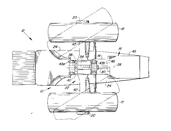
FIG. 3 is a fragmentary bottom view of the apparatus of
FIG. 1 showing the steerable wheels and the longitudinal
position of the oscillation centerline.
FIG. 4 is a fragmentary sectional side view of the
apparatus of FIG. 1.
Detailed Description of the
Preferred Embodiment of the Invention
As shown in FIG. 1, the present invention is embodied in
an apparatus 10 for improving maneuverability of a work
vehicle 12. The work vehicle 12 has an engine 14 mounted on a
frame 16. For exemplary purposes, the work vehicle 12 is
disclosed as an agricultural tractor. Various functional
parts of the work vehicle 12, such as the engine 14 and change
speed transmission 45, may be utilized to form a portion of
the frame 16. A front axle 22 is pivotally connected to the
--- 2 1 5 ;~
frame 16 beneath the engine 14. The axle 22 is a steerable
drive axle and, as will be understood by those skilled in the
art, has steering knuckles at its outer ends that carry final
planetary drives. Steerable drive wheels 18 are mounted on
hubs or ends 20 of the axle 22. The ends 20 are the output of
the final planetary drives. The axle 22 includes a housing or
differential case 40 that substantially is aligned laterally
symmetrically with respect to the oscillation centerline 28.
Axle housings 42 are connected to the differential case 40 in
a fixed manner, such as by bolts, and extend laterally
oppositely therefrom. Although not shown in the drawings but
as will be well understood by those skilled in the art, the
steering knuckles are carried at the outer ends of the axle
housings 42 and the final planetary drives, which include the
ends 20, are secured to the steering knuckles.
The axle 22 includes differential gearing 52 housed in a
chamber 58 formed by the differential case 40 and drive axles
54 housed in the respective axle housings 42 (shown in FIG.
4). The outer ends of the drive axles 54 are connected to the
final planetary drives through U-joints (not shown). The
differential gearing 52 is connected for operation to the
output end 50 of a differential input shaft 34.
As shown in FIGS. 2 and 3, the axle 22 is pivotal about a
fore-and-aft oscillation centerline 28. As the work vehicle
12 moves across the ground, particularly uneven ground, the
axle 22 pivots about the oscillation centerline 28 so that all
four wheels of the work vehicle 12 remain in firm contact with
the ground. For this purpose, at least one pivot support 43
is connected to the frame 16 in a fixed manner, such as by
bolts as shown in FIGS. 2 and 3. The at least one pivot
support 43 preferably includes front and rear pivot blocks or
sleeves 43a, 43b that may be bolted to the frame 16 at the
front and the rear of the differential case 40 of axle 22.
The pivot sleeves 43a, 43b are front and rear oscillation
mounts that attach the axle 22 to the frame 16 for pivotal
movement about the fore-and-aft oscillation centerline 28
.,
-~ 2 1 52~ 1
which is positioned above the centerlines of the drive axles
54.
The front pivot block 43a pivotally receives a projecting
boss formed on a cover 60 of the differential case 40. The
cover 60 is bolted to the main body of the differential case
40. Preferably, the front pivot block 43a rotatively supports
a front bushing 62 that supports a wear sleeve 64 that
supports the cover 60. A retainer plate 72 is screwed to the
cover 60 and abutted against the front pivot block 43a, the
front bushing 62, and the wear sleeve 64. A thrust washer 74
is positioned between the front pivot sleeve 43a and the cover
60.
The rear pivot block 43b preferably pivotally supports a
rear bushing 66 that supports a tubular oscillation support 68
that supports the differential case 40. The rear bushing 66,
the oscillation support 68, the differential case 40, and the
cover 60 cooperate to provide a shaft support that rotatably
supports the drive shaft 30.
A bore 56 extends through the upper portion of the
differential case 40 in substantially concentric alignment
with the oscillation centerline 28. The oscillation support
68 extends into the bore 56 for supporting the axle 22 and is
secured therein by pin 84. A seal 70, for instance, made from
close celled foam rubber, seals the rear pivot sleeve 43b and
the differential case 40.
A drive shaft 30 extends through the oscillation support
68 and the bore 56 in substantially concentric alignment with
the oscillation centerline 28. The forward end 48 of the
drive shaft 30 is connected in a driving manner to the forward
end 49 of the differential input shaft 34 which is supported
by the differential case 40 below and substantially parallel
to the oscillation centerline 28. Preferably, the
differential input shaft 34 is aligned substantially
perpendicularly to the drive axles 54 and has at the output
end 50 a pinion gear that meshes with the differential gearing
52. The drive shaft 30 is connected in the driving manner to
the differential input shaft 34 by intermeshing drive and
, i ~
--- 2~5~4~
driven gears 36 and 38, respectively, which are non-rotatably
mounted on the shafts 30 and 34, respectively.
Upper front bearing 76 supports the drive gear 36 and the
forward end 48 of the drive shaft 30 on the cover 60. Also,
upper rear bearing 78 supports the drive gear 36 and the
forward end 48 of the drive shaft 30 on the main body of the
differential case 40. Oil seal 80 is positioned rear of the
upper rear bearing 78 and between the drive gear 36 and the
differential case 40. In addition, packing "O" ring 82 is
positioned between the drive shaft 30 and the drive gear 36 in
order to seal the main interior of the differential case 40
from the bore 56.
The differential input shaft 34 is supported on the cover
60 and the main body of the differential case 40 by lower
front bearing 88 and lower rear bearing 94, respectively.
The input shaft 34 is held in position by a retainer plate 86
that is screwed to the differential input shaft 34 and abuts
against the lower front bearing 88 to pull the pinion gear at
the output end 50 into engagement with the lower rear bearing
94. A load ring 90 is positioned on the driven shaft 34
between the transmission gear 38 and the lower front bearing
88. Further, a snap ring 92 is positioned on the differential
input shaft 34 and abuts against the driven gear 38 to hold
the driven gear 38 in position against the load ring 90.
The rear end 47 of the drive shaft 30 is connected to a
clutch 46 that is part of the change speed transmission 45.
Preferably, the case of the transmission 45 is formed
structurally so as to make up a portion of the frame 16.
Further, the engine 14 and the transmission 45 cooperate
structurally so as to make up the frame 16 for purposes of
supporting the front portion of the work vehicle 12. A mid-
frame (not shown) positioned rearward of the transmission 45
interconnects structurally the transmission 45 and a
structural rear axle (not shown).
The input (not shown) of the transmission 45 is, as is
conventional, driven by the engine 14 so that the engine power
is transmitted to the driven wheels 18 through the
f~
--- 2 1 52~ 1
transmission 45, clutch 46, drive shaft 30, drive gear 36,
driven gear 38, differential input shaft 34, differential
gearing 52, and drive axles 54.
Alignment of the drive shaft 30 along the oscillation
centerline 28 eliminates the need for a U-joint in the
transmission of rotary motion to the axle 22 because the
position of the drive shaft 30 is not affected by oscillation
of the axle 22. This also places the drive shaft 30 close to
the underside of the frame 16, providing good clearance
between the ground and the drive shaft 30. Partially because
the drive shaft 30 extends through the bore 56, partially
because of the elimination of U-joints associated with the
drive shaft 30, and partially because of the high clearance of
the drive shaft 30 with respect to the ground, the need for
shielding of the drive shaft 30 is reduced or eliminated.
Because the drive shaft 30 remains on the oscillation
centerline 28 during oscillation of the axle 22 and because of
the elimination of U-Joints and shielding associated with the
drive shaft 30, the lateral space requirements for
transmitting the rotary motion from the transmission 45 to the
axle 22 is kept at a minimum. Therefore, the axle 22 may
receive power notwithstanding space limitations between the
axle 22 and the transmission 45 created by positioning the
transmission 45 forward of a cab 26 mounted on the frame 16.
As shown in FIG. 3, the frame 16 is of a reduced width in
the area of the engine 14 and defines voids or passages 24 for
penetration by the wheels 18 as the wheels 18 are turned and
visibility past the axle 22 from the cab 26 which is mounted
on the frame 16. The wheels 18 are shown as penetrating the
passages 24 in phantom lines in FIG. 3. The reduction in
space requirements for the drive shaft 30 avoids interference
between the wheels 18 and the drive shaft 30 as the wheels 18
are turned into the passages 24.
The phantom line position of the wheels 18 shown in FIG.
3 assumes the axle 22 is at a centered or level position. As
the axle 22 oscillates in either direction, one or the other
of the wheels 18, namely, the one of the wheels 18 on the end
_
2 1 5284 1
of the axle 22 which moves up with respect to the frame 16,
would normally tend to move closer to and possibly interfere
with the frame 16 or another tractor part. However, because
the axes of the input shaft 34 and the differential gearing 52
are positioned well below the oscillation centerline 28,
oscillation of the axle 22 will result in a lateral shifting
of the axle 22 to move the otherwise potentially interfering
wheel 18 away from the frame 16. The lateral shifting
represents the lateral component of the radial swing or pivot
of the axle 22 with respect to the oscillation centerline 28.
Of course, the pivot of the axle 22 also includes a vertical
component.
The opposite wheel 18, in particular, the one on the end
of the axle 22 which moves downward with respect to the frame
16, is already positioned below the tractor frame 16, so its
continued downward movement will not cause interference.
Also, because of the high position of the drive shaft 30 and
its narrow lateral shape, there is no interference between the
drive shaft 30 and the wheel 18 as the downwardly swinging
wheel 18 shifts downwardly and inwardly with respect to the
frame 16. The pivot of the axle 22 is such that at about ten
degrees oscillation of the axle 22, the downwardly swinging
wheel 18 nearly encroaches on a vertical plane passing through
the longitudinal centerline of the work vehicle 12.
Having shown and described a specific embodiment of the
invention, various obvious modifications of the invention will
become apparent to those skilled in the art and can be made
without departing from the spirit or scope of the invention.
For example, the differential input shaft 34 could enter the
differential case 40 from the rear and all the advantages of
the invention would be retained. Therefore, the invention
should not be limited to the detailed description or the
specific illustrations, but only to the fair scope of the
following claims.