Note : Les descriptions sont présentées dans la langue officielle dans laquelle elles ont été soumises.
012153363
Application Of: Parag J. Mehta, et al
For: Method Of Assembling Wiring Devices In Continuous Succession
Background Of The Invention
The present invention relates to methods of assembling a plurality
of elements to produce an electrical wiring device of the type having a
mounting strap for supporting the device in a junction box, or the like.
More specifically, 'the invention relates to a method of assembling
wiring devices such as wall receptacles in a continuous sequence in a
fully automated manner.
As labor costs have risen over the years, automated assembly of
products from a plurality of separately fabricated elements has steadily
become more popular. One of the principal requirements in automated
assembly of a number of diverse parts is the precise positioning and
indexing of the parts as they are placed by robotic or other automated
means in the required relative positions. Achieving this requirement is
often the most difficult and costly element in the implementation of the
process. This is notably the case in the automated assembly of
electrical wiring devices.
It is a principal object of the present invention to provide a
novel and improved method of assembling electrical wiring devices.
Another object is to provide a highly reliable yet relatively
inexpensive method o:E assembling electrical wiring devices.
A further object is to provide an automated method of producing
wiring devices of thE; type having a mounting strap which involves steps
in the fabrication o:E the mounting strap as well as assembly therewith
of separately fabric~~ted elements.
1
CA 02153363 2002-O1-17
Still another obj ect is to provide a novel method of producing
electrical wiring devices in a rapid, continuous sequence.
Other objects will in part be obvious and will in part appear
hereinafter.
S Summary Of The Invention
The invention is disclosed in the context of automated
assembly of a duplex wall receptacle of the type disclosed in
commonly owned U.S. Patent No. 5,472,350 of December 5, 1995. The
receptacle basically consists of five elements, namely, front and
rear housing sections, a pair of terminal elements and a mounting
strap, plus screws inserted in the terminals and strap for
connection thereto of hot, neutral and grounding conductors and
screws extending through openings in end portions of the strap for
mounting the device in a junction box, or the like. Also, ground
contacts for receiving the grounding prongs of electrical plugs are
staked to the mounting strap.
In the assembly method of the invention, a continuous,
elongated strip of galvanized steel, or other material from which
the mounting straps are formed, is fed in the direction of the
longitudinal axis of the strip. The strip is sequentially moved
and stopped, the distance of each movement being equal to the width
of one of the finished mounting straps, plus the width of a scrap
portion. At a first position or station at which strip movement
stops, openings are cut or punched by conventional tooling at
predetermined positions to form a blank from which a finished
mounting strap will be formed. Also, threads are formed in two of
the punched openings. At the next two stations, separate,
elongated strips of copper, previously cut in predetermined
2
~~2~53363
areas to form blanks which will become ground contacts, are fed in
directions parallel. to their respective longitudinal axes and
perpendicular to then axis of the first strip. At each of these two
stations one of the around contact blanks is severed from its respective
strip, moved downwardly and staked to a mounting strip blank in covering
relation to respective ones of the openings previously formed therein.
At succeeding stations, the mounting strap and ground contact
blanks are further formed by bending operations and a screw is inserted
in one of the tapped openings in the mounting strap blank; the rear
housing section is moved upwardly into mating engagement with and staked
to a mounting strip blank; the two terminals with conductor connection
screws fully inserted are moved downwardly into positions within the
rear housing section; the junction box mounting screws are moved
downwardly through respective openings in opposite end portions of the
mounting strip blank and cardboard retainers are placed on the mounting
screws; and the froni~ housing section or cover is moved downwardly into
mating engagement with the rear housing section, and the two sections
are joined by ultrasonic welding. During all of these operations the
mounting strap blanks remain rigidly connected in side-by-side relation
to one another at opposite end portions thereof. As a final step, the
scrap portion is removed between the endmost mounting strap and the next
preceding mounting strap to provide a fully assembled receptacle.
Electrical testing may be performed, if desired, before the receptacles
are severed from the continuous strip. The conductor connecting screws
are backed out of their respective tapped openings in the terminals by
robotic screwdrivers before final packaging.
3
CA 02153363 2002-O1-17
The foregoing and other features of the invention will be more
readily understood and fully appreciated from the following
detailed disclosure, taken in conjunction with the accompanying
drawings.
Brief Description Of The DrawincL
Figure 1 is an exploded, perspective view of a duplex wall
receptacle, representing an electrical wiring device of the type
assembled by the present invention;
Figure 2 is a perspective view of the receptacle of Figure 1
in fully assembled condition;
Figure 3 is a top plan view of a succession of assembled
receptacles joined at each end by portions of the sheet metal strip
from which the mounting straps are formed;
Figure 4 is a side elevational view of the receptacles of
Figure 3;
Figures 5 and 6 are bottom plan and end elevational views
thereof, respectively; and
Figures 7 through 17 are perspective views showing the
elements of the receptacle of Figure 1 in a succession of forming
and assembly steps to illustrate the sequence of steps in the
assembly of a finished receptacle according to the present
invention.
Detailed Description
Referring now to the drawings, an electrical wiring device in
the form of a duplex receptacle, denoted generally by reference
numeral 10, is seen with its component elements in exploded,
perspective view in Figure l, and in fully assembled condition in
Figure 2. Receptacle 10 is identical to the receptacle which is
the subject of the previously referenced U.S. patent which can
provide any details which may be useful in the further
understanding of the present invention.
Receptacle 10 includes front and rear housing sections, termed
4
CA 02153363 2002-O1-17
cover 12 and base 14, respectively, mounting strap 16 and a pair of
terminals 18 and 20. Respective pairs of screws 22 and 24 engage
threaded openings in terminals 18 and 20 for securing the stripped
ends of electrical wires thereto. Cover 12 includes two sets of
S openings through which the blades of a pair of electrical plugs may
be inserted for engagement by female contacts of terminals 18 and
20, and by ground contacts 28 and 30 each staked to mounting strap
16 over respective openings therein. The mounting strap is
commonly formed from a sheet of galvanized steel and the grounding
contacts from a sheet of copper alloy. Screw 32 engages a threaded
opening in depending tab 34 on mounting strap 16 and ears 36 extend
outwardly on each side of the screw head to assist in looping the
ground wire around screw 32 during installation. End portions 38
and 40 of strap 16 extend outwardly from opposite ends of the fully
assembled receptacle, and screws 42 and 44 extend loosely through
openings in the respective strap end portions for mounting
receptacle 10 in a standard junction box. Screws 42 and 44 are
retained in the strap openings prior to installation by cardboard
retainers 46 and 48, as is conventional.
The present invention is concerned with automated assembly of
receptacle 10, or other wiring devices having a mounting strap with
end portions extending outwardly from opposite ends of the device.
In Figures 3-6 are shown a plurality of receptacles 10 in
side-by-side relation, end portions 38 and 40 of the mounting strap
of each
5
02153363
receptacle being integrally attached to the strap end portions of the
adjacent receptacle; on both sides. Receptacles 10, as will be
explained in detail hereinafter, have been assembled according to the
present invention, in a series of steps involving sequential movement of
the continuous strip of material from which the mounting straps are
formed in a direction parallel to the longitudinal axis of the strip.
The strip is moved in increments equal to the width of the mounting
strap end portions 38 and 40, plus the width of a scrap portion (e. g.,
.080"), one of which is indicated in the shaded portion of Figure 3
denoted by reference numeral 41. The incremented distance of travel is
indicated in Figure 3 by distance D.
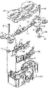
Referring now to Figure 7, an elongated strip 50 of the sheet metal
from which the mounting straps are formed is fed from a supply (not
shown) in the direction of arrow 52, i.e., along the longitudinal axis
of strip 50. Strip 50 is alternately moved (by distance D) and stopped,
the forming and assembly operations being performed simultaneously at
successive positions or stations while the strip is in a stationary
position. The first step in the process is the cutting or punching by
conventional tooling (not shown) of predetermined areas of strip 50. A
relatively large area, denoted by reference numeral 54, between side
edges 56 and 58 is removed from the strip leaving a cut-out area
bordered by a continuous succession of straight lines. At the same
time, a number of holes are punched in strip 50, such holes being
indicated by reference numerals 60, 62, 64, 66, 68, 70, 72, 74, 76 and
78. Also, a small embossed area 79 is formed inwardly of opening 64 for
purposes of strengthening the mounting strap. Internal threads are
6
02153363
formed in holes 68 and 70 by conventional taps.
At the two operational stations following that shown in Figure 7,
a pair of additional sheet metal strips 80 and 82 are fed from separate
supplies (not shown) in parallel directions, perpendicular to the
direction of movement of strip 50. The longitudinal axes of strips 80
and 82 are spaced by distance D. Strips 80 and 82 are alternately moved
and stopped, in the ;game manner as strip 50, and are punched and cut by
appropriate tooling at positions laterally adjacent strip 50 to form a
succession of mutually connected blanks 84, such blanks being identical
in the two strips.
Strip 80 is fed forwardly above the portion of strip 50 which lies
between two successive cutout areas 54 until the endmost blank 84' is in
covering relation to opening 66, as shown in Figure 8. Blank 84' is
then cut from strip i30, moved downwardly a small distance and staked to
strip 50 at the position indicated by reference numeral 86. Likewise,
strip 82 is fed forwardly until the endmost blank 84" is in covering
relation to one of openings 72 in strip 50. Blank 84" is severed from
strip 82 and staked to strip 50 at 88. It will be noted that the
configuration of elements is such that blanks 84' and 84" may be severed
adjacent an edge pori:ion of cutout area 54. Scrap portions 80' and 82'
of strips 80 and 82, respectively, which remain after removal of blanks
84' and 84" are severed after passing edge 56 of strip 50.
After attachment of blanks 84' and 84" to the portions of strip 50
separating cutout areas 54, strip 50 comprises a series of mutually
attached blanks for t:he formation of mounting straps, as seen in Figure
9. Blanks 84' and 84" are then bent by suitable tooling so that
7
~az153363
portions extend into openings 66 and 72, as seen in Figure 10, the
blanks now forming completed ground contacts, numbered 28 and 30,
respectively, as in ~?igure 1. Such contacts will resiliently engage the
grounding prongs of electrical plugs which are connected to receptacle
10. At the same time, ears 36 are bent upwardly on the mounting strap
blanks.
At succeeding operational stations, openings 70 are tapped, screws
32 are threaded into openings 70, and tabs 34 are bent downwardly, as
seen in Figures 11 and 12, respectively. Assembly of the other
components, which hive been separately fabricated, with the mounting
strap blanks is performed as strip 50 is advanced to succeeding
operational stations. The first such step, as illustrated in Figure 13,
is the upward movement of bases 14 into mating relation with the
mounting strap blanks. As explained more fully in the previously
referenced application, this relation is defined by portions of the
mounting strap being placed between and upon wall portions of base 14,
which are then slightly deformed at appropriate locations to provide a
staked connection between the bases and mounting strap blanks.
Bases 14 are supported in this position at subsequent stations
where terminals 18 and 20 are moved downwardly into appropriately formed
recesses in bases 14, and mounting screws 42 and 44 are inserted through
openings 64 and 78, :respectively, as seen in Figures 14 and 15. Also,
cardboard retainers ~~6 and 48 are moved upwardly to engage the threaded
portions of the screws adjacent openings 64 and 78. Covers 12 are then
moved downwardly into mating relation with bases 14, as shown in Figure
16, with medial portions of the mounting strip blanks captured between,
8
~V~2153363
and end portions of the strap extending outwardly from the cover and
base. Opposing surfaces of cover 12 and base 14 are then permanently
joined by ultrasonic welding of the thermoplastic materials from which
the cover and base are molded.
The final steps. in the assembly operation are then performed, as
shown in Figure 17. By simultaneous cuts, scrap pieces 41 are severed
from between endmost receptacle 10' and the next preceding receptacle.
Scrap pieces 41 taper outwardly on both sides and at both ends to
provide angled corners on the mounting strap ears. The scrap portions
provide the necessary spacing between succeeding receptacles while
keeping the width of the mounting strap ears at the desired dimension.
At the same time the scrap is cut, score marks 90 and 92 are formed to
permit easy removal, if desired at the time of installation, of the
mounting strap ears. If desired, electrical testing of the receptacles
may be performed prior to severing thereof from the continuous strip.
The severed receptacle, indicated by reference numeral 10', drops
downwardly from the :trip and is moved laterally, as indicated by arrow
102, to a position where robotic screwdrivers (not shown) back out
terminals screws 22 and 24 so that the receptacle is in a condition
ready for installation and wiring. Screws 22 and 24 are fully inserted
in their respective threaded openings during the assembly operations in
order to provide the. necessary clearance between adjacent receptacles
while mutually attaclhed in the continuous strip.
From the foregoing, it will be understood that the present
invention provides a method of forming receptacle mounting straps in a
continuous, essentia:Lly rigid strip, and assembling therewith all other
9
~a~~53363
elements of the receptacle in a rapid, efficient and fully automated
manner. It will al:ao be understood that while all stations at which
operations are performed have been illustrated, these are not
necessarily immediately successive stationary positions of the strip;
that is, in order to provide the necessary room for tooling. The strip
may be indexed more than once between successive operations. In any
event, the continuou:~ and essentially rigid nature of strip 50 provides
the necessary precise positioning of the elements at each operational
station.