Note : Les descriptions sont présentées dans la langue officielle dans laquelle elles ont été soumises.
-- 21539 14
STABILIZER LINK
Technical Field of the Invention
The present invention relates to a stabilizer
or torsion bar link that can be used to stabilize the
suspension for a vehicle, such as, for example, a bus or
a car.
Background of the Invention
A suspension assembly for a bus or other
vehicle usually includes, among other components, a
torsion bar and a connecting or stabilizer link. The
torsion bar (which also may be called a stabilizer or
sway bar) is generally affixed to the vehicle frame with
the stabilizer link functioning as the connecting member
to the axle. The torsion bar absorbs torsional loading
while the stabilizer link additionally must act as a
shock absorber.
The stabilizer link can have a generally U-
shaped construction that includes a metal housing and a
pair of metal shafts permanently secured to the housing.
The shafts are also connected to other components of the
assembly, such as the axle plate (or associated part) and
the torsion bar.
It is known to use rubber as an intermediary to
permanently secure the shafts to the housing to add
flexibility to the link so that the stabilizer link is
better able to absorb road shocks. To construct such a
link, rubber is molded to one end of each shaft. The
ends of the shaft are then inserted into the bores
defined in the housing. The housing is crimped radially
213914
- 2 -
around each bore to permanently secure the shafts to the
housing.
A disadvantage of this known stabilizer link,
however, is that it has a relatively short life
expectancy because the rubber tends to shear or become
worn relatively quickly and much sooner than the rest of
the components. Thus, once the rubber shears or becomes
worn, the entire stabilizer link is no longer useful and
must be replaced.
In an attempt to provide a stabilizer link with
a longer life expectancy, an all metal stabilizer link
that uses all metal ball studs has been developed.
Although this stabilizer link indeed has a longer life
expectancy than the link discussed above, it is
undesirable because it lacks flexibility and does not
absorb road shocks as well as the other link. As a
result, the all metal link tends to transfer stress to
the suspension which, over time, will shorten the life of
various parts in the suspension.
What is needed is a stabilizer link that is
capable of effectively absorbing road shocks better than
the prior art stabilizer links, and that is more
economical than the prior art stabilizer links. Such a
link should include a flexible element to absorb the
shocks, but should also address the problem of short life
expectancy associated with the known link having a
flexible element. The present invention meets these
desires.
Summary of the Iswention
The present invention provides a stabilizer
link for a steering and suspension assembly for a bus or
other vehicle. In its preferred embodiment, it includes
a pair of shafts or studs, and a housing that is defined
by a pair of eyes or cylinders that are joined together
by a rod or stem. Each cylinder defines a pair of
~1~391~
- 3 -
adjoining or contiguous, tapered bores opening in
opposite directions for receiving a pair of bushings.
Preferably, both ends of each shaft are
threaded, with a distal threaded end of each shaft being
secured to another component of the assembly such as the
axle plate (or associated part) or torsion bar. Each
shaft may be secured to the housing by replaceable
components, such as, a pair of proximal and distal
retaining washers, a pair of bushings, and a fastener
such as a nut secured to a proximal threaded end of the
shaft .
The bushings preferably are constructed of
polyurethane, which has a longer life expectancy than
rubber or synthetic rubber and has better shock absorbing
dynamics. Polyurethane also has a relatively high degree
of elasticity. Preferably, the polyurethane has a
hardness of about 85 to about 95 durometers on the Shore
A scale, and optimally about 90 durometers.
Alternatively, the bushings may be constructed of rubber
or synthetic rubber that preferably has a hardness of
about 70 durometers.
Each pair of bushings is received within one of
the respective pairs of bores defined by the cylinders.
Desirably, each bushing has a first frustoconical wall
with a taper that narrows toward the end of the bushing.
The first frustoconical outer walls preferably complement
the tapered bores. This construction eliminates or
reduces lateral displacement of the housing relative to
the bushings and. shaft. The tapers also eliminate or
reduce longitudinal displacement of each bushing in the
direction of its adjacent bushing.
Each bushing may also have a second
frustoconical outer wall with a taper that narrows toward
the other end of the bushing, which extends outside the
bore. This construction tends to relieve pressure and
'' 1 2~~39~.~
- 4 -
avoid pinching of the bushing between the washers and the
cylinders when the bushing is under compression during
service.
Preferably, the retaining washers are disposed
about the shafts, and abut the ends of the bushings that
extend outside the bores. The holes defined by the
proximal and distal washers are different sizes. Each
retaining washer may have a circumferential flange angled
with respect to a flat portion to form a dish shape
configuration. The flanges of each pair of proximal and
distal washers face away from the bushings, which also
helps to relieve pressure when the bushing is under
compression yet still contain the bushings in the
housings. With this construction, when the shaft is
deflected from center, it causes further compression of
the bushings. The orientation of the dish-shaped washers
allows relief from this compression. The dish shape also
provides a surface for the bushing to "roll" against.
Alternatively, however, the dish shaped
retaining washers can face each other, or the washers
instead can be flat washers.
In the preferred embodiment, the nuts are
conventional castle nuts adapted to engage a cotter pin
for securing the nuts. With this embodiment, one of the
threaded ends of the shaft also defines a cotter pin hole
for receiving the cotter pin. This construction tends to
be more reliable against shock and vibration than other
alternatives, and also avoids causing damage to the
threads of the shafts. Alternatively, however, a nylon
insert nut or an all metal lock nut can be used.
The preferred embodiment of the present
invention provides a stabilizer link that is more
economical than the prior art links because its
components can be easily and quickly replaced when they
fail or become worn. As a result, the link can be reused
2i5391~
and does not have to be discarded when one of its
components fails or becomes worn.
In this regard, cost savings likely will be
appreciated most in connection with the replacement of
bushings since they tend to have substantially shorter
lives than the rest of the components of the stabilizer
link and also tend to be significantly less expensive
than the housing and shafts. Thus, with the present
invention, the bushings can be continuously replaced as
they become worn, thereby substantially extending the
life of the stabilizer link.
If desired, the stabilizer link may be sold
together as a fully-assembled link. Alternatively, all
of the components may be sold together (e. g. the housing,
retaining washers, bushings, nuts and pins) in a
container such as a box or bag as a kit, if desired. The
components can then be assembled and installed on a
vehicle. Thereafter, when the bushings (or other
components) become worn, new bushings (or other
components) can be obtained separately from the kit, and
then can be replaced.
Similarly, the components that tend to be
replaced more frequently can also be sold together as a
kit. For example, two pairs of bushings, two pairs of
retaining washers, a pair of castle nuts and a pair of
cotter pins may be sold together in a package to be used
when any or all of these original (or previously
replaced) components become worn. Such a kit enables
quick and easy replacement of the corresponding
components.
Numerous other advantages and features of the
present invention will become readily apparent from the
following detailed description of the invention and the
embodiments thereof, from the claims and from the
accompanying drawings.
.
'~ 2153~~4
- 6 -
Brief Description of the Drawincts
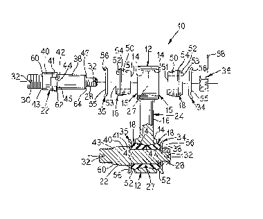
FIGURE 1 is an exploded perspective view of a
stabilizer link in accordance with one embodiment of the
invention;
FIGURE 2 is a partial exploded and partial
cross section view of a stabilizer link similar to the
link of FIG. l;
FIGURE 3 is a partial exploded and partial
cross section view of a stabilizer link in accordance
with an alternative embodiment of the invention,
illustrating the dish-shaped retaining washers facing
each other and conventional nuts secured to the shafts;
FIGURE 4 is a plan view of the side of the
housing of the stabilizer link of FIGURES 2, illustrating
with dotted lines the inner walls of the cylinders;
FIGURE 5 is a plan view of the top of the
housing of FIGURE 4; and
FIGURE 6 and is a cross section view taken
along the lines 6-5 of FIGURE 5.
Detailed Description of the Invention
As illustrated in FIGURES 1-6, the stabilizer
link 10 in accordance with the preferred embodiments of
the invention includes a pair of cylinders or eyes 12.
Each cylinder 12 defines a pair of connected or
contiguous, tapered bores 14 opening in opposite
directions along a common axis to define respective open
ends 15. The cylinders 12 are joined by a stem or a rod
16 so that the axes of the pairs of bores 14 are
substantially parallel. Two pairs of bushings 18 are
also included, and each pair is matingly received into a
respective pair of bores 14. Each bushing 18 defines a
cylindrical aperture or channel 20 along its axis.
The stabilizer link 10 also includes two shafts
22, each of which is received into the respective pair of
bores 14 defined by the cylinder 12 and the channels 20
"' ~1~3~~4
7 _
defined by the respective pair of bushings 18. Means for
retaining the shafts 22 within the bores 14 and channels
20 are also included.
The cylinders 12 and stem 16 together define a
housing 24 that may be a one-piece housing made from a
molded polymer or metal (see, e.g., FIGURE 1).
Alternatively, the housing 24 may be a three-piece steel
weldment wherein the cylinders 12 are welded to the stem
16 (see, e.g., FIGURES 2-5). In this alternative
construction, the cylinders 12 may, for example, be a
Monroe Shock Stock No. 11963. The stem 16 preferably has
a circular cross section substantially along its length.
Each cylinder includes an inner wall 26 that
defines one of the pairs of bores 14 and a central ridge
27 that divides the bores 14. The ridge 27 may define a
flat face that extends parallel to the axis of the bores,
or may have a rounded face. The inner walls 26 of each
cylinder 12 adjacent each end 29 of the cylinder may be
rounded (FIGURE 6).
Preferably, each shaft 22 defines a proximal
end 28 and a distal end 30, both of which are threaded
and include cotter pin holes 32. The distal ends 30 of
shafts 22 are secured to another component of the
steering and suspension assembly. For example, the
distal end 30 of one shaft 22 may be secured to the axle
plate (or associated part) and the distal end of the
other shaft may be secured to the stabilizer bar. The
cotter pin hole 32 on the distal end 30 of the threaded
shaft 22 may be used to secure a fastening nut that is
used to attach the shaft to the assembly component. The
diameter of the distal end 30 may be greater than the
diameter of the proximal end 28.
The means for retaining each shaft 22 within
the bores 14 includes one of the pairs of bushings 18, a
pair of retaining washers, namely a proximal washer 34
,,._;
21~39~.~
,,,,.. _
_8_
and a distal washer 35, and a fastener such as nut 36
secured to the threaded proximal end of the shaft.
Each shaft 22 includes a bushing portion 38
adjacent the proximal end 28, a tapered portion 40
adjacent the distal end 30, and a central portion 41
joining the bushing portion and the tapered portion. One
of the pairs of bushings 18 and one of the distal washers
35 is disposed about the bushing portion 38 of each
shaft. The diameter of the bushing portion corresponds
to the diameters of the channels 20 of the bushings 18
and the distal washer 35, and is less than the diameters
of the tapered and central portions 40, 41.
The tapered portion 40 of the shaft 22 defines
a gradual inward tapering in the direction of the distal
end 30 of the shaft 22 for engaging mating surfaces on
the components of the steering and suspension assembly.
The central portion 41 defines a first lateral face 43
adjacent the distal end 30 and a second lateral face 45
adjacent the bushing portion 38. The bushing portion
defines a third lateral face 47 adjacent the proximal end
28. The shaft 22 may be constructed of any suitable
metal such as a steel with an elevated hardness commonly
known as "Stressproof", or of any other suitable
material.
Each shaft 22 may also include a pair of
diametrically-opposed wrench flats 42 to be used to
tighten the nuts 36. In the illustrated embodiments, the
wrench flats are formed on the central portion 41,
extending onto the tapered portion 40. Alternatively,
alternate "drive" methods could also be used such as, for
example, a hex socket broached or forged into the end of
the stud. In addition, a radius corner portion 44 may be
formed at the distal end of the bushing portion 41
adjacent the lateral face 45 for reducing the stress that
tends to cause the formation of fractures. Tapered or
,.-
21~3~14
- 9 -
broken corner portions 60, 62 and 64 may be defined on
the periphery of respective lateral faces 43, 45 and 47
to eliminate sharp edges.
The bushings 18 desirably are substantially the
same in configuration and material. In the preferred
embodiment, the bushings 18 are constructed of
polyurethane, which has a longer life expectancy than
rubber or synthetic rubber and has better shock absorbing
dynamics. Polyurethane also has a relatively high degree
of elasticity. Preferably, the polyurethane has a
hardness of about 85 about 95, and optimally about 90
durometers on the Shore A scale. The bushings 18 may,
for example, be polyurethane bushings that are available
from Gabriel as part No. #415025, or a standard
polyurethane bushings that can be obtained from Euclid.
Each bushing 18 includes a pair of flat ends
51, 53 that extend substantially perpendicular to the
axes of the bores, and first and second frustoconical
outer bushing walls 50, 52 that are joined together by a
neck 54. The flat ends 53 of each pair of bushings 18
are in abutting engagement within a respective cylinder
12. The outer diameters of the flat ends 51, 53 are
substantially the same.
The first outer bushing wall 50 is received
substantially within its respective bore 14, and the
second outer bushing wall 52 extends at least partially
beyond its respective bore 14. Desirably, the first
outer bushing wall 50 extends most of the length of the
bushing 18, is tapered inwardly towards the proximal end
of the bushing, and has a more gradual taper than the
second outer bushing wall 52. The neck 54 may be
inwardly tapered toward the first outer bushing wall, and
its length is substantially less than the second outer
bushing wall 52. The first outer bushing walls 50
complement the tapered bores 14. This construction
21~39~.4
.,.... _
- 10 -
eliminates or reduces lateral displacement of the housing
24 relative to the bushings 18. It also eliminates or
reduces the longitudinal movement of each bushing 18 in
the proximal direction.
Despite the advantages of the polyurethane
bushing, it is appreciated that the bushings 18 can
instead be constructed of any other suitable material,
such as rubber or synthetic rubber. Preferably, the
material chosen has a relatively long life expectancy.
In this regard, some important characteristics to
consider in choosing a suitable material are its ability
to withstand adverse weather condition and its ability to
resist water, oil and ozone.
It is noted that natural and most synthetic
rubbers have their best mechanical characteristics
(tensile strength, elongation, compression set, etc.)
when produced at a 70 durometer. Typically, the rubber
is then compressed to get the hardness needed to
withstand the shock loads. Polyurethane bushings, on the
other hand, generally do not need the same degree of
compression because of the increased hardness of
polyurethane.
Each pair of proximal and distal retaining
washers 34, 35 is disposed about one of the shafts 22.
Each washer 34, 35 has an outer diameter substantially
the same as or slightly less than the outer diameter of
the cylinders 12. Each distal washer 35 is disposed
about one of the respective bushing portions 38, and is
disposed between and in abutting engagement with the flat
end 53 of one of the bushings 18 and the lateral face 45
of one of the shafts 22. The inner diameter of the
distal washers 35 complements the diameter of the bushing
portion 38 and radius corner portion 44.
The proximal washer 34 is disposed about the
proximal end 28 of one of the respective shafts 22, and
'~ 21~39~~~
a
- 11 -
is disposed between and in abutting engagement with
another bushing 18 and one of the nuts 36. The inner
diameter of the proximal washer 34 complements the
diameter of the radius corner portion 44 of the shaft 22.
The inner diameter of the proximal washer 34 is less than
the inner diameter of the distal washer 34.
Desirably, each washer 34, 35 includes a flat
portion 55 and a circumferential flange 56 angled with
respect to the flat portion to form a dish shape, and the
flanges extend in opposite directions away from the
respective pair of bushings 18. The flanges preferably
extend at an angle of about 15 degrees to about 45
degrees and optimally at about 30 degrees. The outer
diameter of the flat portion 55 is about the same as the
outer diameters of the flat ends 51, 53 of the bushings
18. The thicknesses of the proximal and distal washers
34, 35 may be substantially the same.
Preferably, prior to assembly, the length of
the bushing portion 38 of the shaft 22 is less than the
dimension defined by the length of one of the pairs of
bushings 18 plus the thickness of the flat portion 55 of
the distal washer 35. During assembly, however, the
bushings are compressed so that, in the assembled link,
the length of the bushing portion 38 of the shaft 22 is
about the same as the dimension defined by the length of
one of the pairs of bushings 18 plus the thickness of the
flat portion 55 of the distal washers 35.
The flanges 56, the inward tapering of the
second outer bushing walls 52 of the bushings 18, and the
rounded off inner walls 26 of the cylinders 12 tend to
relieve pressure on the bushings when they are under
compression, which can occur when the shaft 22 is
deflected off center from absorbing road shocks. This
construction provides an area in which the bushing can
expand while under pressure. It also reduces the
~153g 14
- 12 -
likelihood of any "pinching" of the bushings 18 between
the washers and cylinders 12. The dish-shaped retaining
washers 34, 35 also provides a surface for the bushing to
"roll" against.
If desired, however, the flanges 56 can face
the same direction (see FIGURE 3), or, instead, flat
retaining washers can be used.
The nuts 36 may be conventional nuts (see
FIGURE 3) but, preferably are conventional castle nuts
adapted to receive a cotter pin 58 used to secure the
nuts (see FIGURE 2). The cotter pin 58 also extends
through one of the cotter pin holes 32 formed on the
shafts 22. Generally, application of about 70 foot-
pounds of torque will sufficiently secure the nuts to the
assembly. An advantage of this construction is that it
is more reliable against shock and vibration than other
alternate means of securing the nut 36 to the shaft 22.
Also, this construction avoids damaging the threads of
the shafts 22. Alternatively, however, a nylon insert or
an all metal lock nut can be used.
Those of ordinary skill in the art will
recognize that various dimensions and materials can be
used depending on the exact use of the present invention.
One of the advantages of the stabilizer link 10
in accordance with the present invention relates to the
replaceability of the individual components, such as the
bushings 18 which tend to have shorter life than the
remaining components of the stabilizer bar. When the
bushings 18 are no longer useful due to wear and tear (or
any other reason), they can be replaced quickly and
~...,:
213914
- 13 -
easily. Because the rest of the components can still be
used, this results in cost savings each time the bushings
are replaced.
If desired, all the components may be sold
together (e.g., the housing 24, shafts 22, bushings 18,
retaining washers 34, 35, nuts 36 and pins 58) in a
container such as a box or bag as a kit, if desired. The
components can then be assembled and installed on a
vehicle. Thereafter, when the bushings 18 become worn,
new bushings can be obtained separately from the kit, and
then can be replaced in accordance with the above. It is
appreciated that other components may be individually
replaced.
Additionally, some of the components which may
need to be replaced on a more frequent basis may be sold
together in a container such as a box or bag as a kit, if
desired. When the corresponding components on the link
10 become worn, the kit can be used to replace the worn
components.
For example, two pairs of bushings 18 and two
pairs of proximal and distal retaining washers 34, 35 may
be sold together as a kit for replacement of the
corresponding components on the link 10. Such a kit
enables the quick and easy replacement of the
corresponding components. The bushings, for example,
have the same configuration and are constructed of the
same materials, and, thus, they can be installed quickly
and easily since virtually no time is spent determining
where each individual bushing goes. Since the proximal
and distal washers 34, 35 have different inner diameters
which correspond to the portions of the shaft on which
they are to be installed, they also can be installed
relatively quickly.
If desired, the kit may also include one pair
of nuts 36 to avoid having to reuse nuts that may be
21~39~.4
- 14 -
difficult to re-install due to corrosion or wear and
tear. If the nuts are castle nuts, a pair of cotter pins
may also be included as part of the kit to enhance the
quick and easy replacement of the castle nuts.
The foregoing description is for purposes of
illustration only and is not intended to limit the scope
of protection accorded this invention. The scope of
protection is to be measured by the following claims,
which should be interpreted as broadly as the inventive
contribution permits.