Sélection de la langue

Search

Sommaire du brevet 2154031 

Énoncé de désistement de responsabilité concernant l'information provenant de tiers

Une partie des informations de ce site Web a été fournie par des sources externes. Le gouvernement du Canada n'assume aucune responsabilité concernant la précision, l'actualité ou la fiabilité des informations fournies par les sources externes. Les utilisateurs qui désirent employer cette information devraient consulter directement la source des informations. Le contenu fourni par les sources externes n'est pas assujetti aux exigences sur les langues officielles, la protection des renseignements personnels et l'accessibilité.

Disponibilité de l'Abrégé et des Revendications

L'apparition de différences dans le texte et l'image des Revendications et de l'Abrégé dépend du moment auquel le document est publié. Les textes des Revendications et de l'Abrégé sont affichés :

  • lorsque la demande peut être examinée par le public;
  • lorsque le brevet est émis (délivrance).
(12) Demande de brevet: (11) CA 2154031
(54) Titre français: POTEAU POUR LIGNES DE TRANSPORT D'ELECTRICITE
(54) Titre anglais: WR-POLE
Statut: Réputée abandonnée et au-delà du délai pour le rétablissement - en attente de la réponse à l’avis de communication rejetée
Données bibliographiques
Abrégés

Abrégé anglais


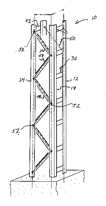
There is provided a pole or tower structure for
supporting electric power supply cables wherein the
structure has a generally rectangular configuration having
four faces, the structure comprising a first ladder assembly
having a pair of longitudinally extending members with
generally parallel battens welded thereto interconnecting
the members, a second ladder structure also having a
plurality of battens interconnecting two longitudinally
extending members, and each of the ladder structures being
interconnected by braces mechanically attached to adjacent
longitudinally extending members, all of the faces
preferably having a generally tapered configuration from the
bottom to the top. The structure can be easily engineered
to replace wood poles presently used and allows for a
relatively inexpensive structure providing ease of assembly
at the site.

Revendications

Note : Les revendications sont présentées dans la langue officielle dans laquelle elles ont été soumises.


The embodiments of an invention in which an
exclusive property or privilege is claimed is defined as
follows:
1. A tower structure suitable for supporting electric
power supply cables, the tower structure comprising four
substantially vertically extending members arranged in a
generally rectangular configuration to provide four faces, a
first pair of substantially vertically extending members
having extending therebetween a plurality of generally
parallel battens, said battens being substantially
perpendicular to said longitudinally extending member, a
second pair of said substantially vertically extending
members also being secured together by a plurality of
generally parallel battens, said battens being welded to
said vertically extending members, and a plurality of
diagonally extending braces extending between adjacent
members not secured together by said battens.
2. The tower structure of Claim 1 wherein each of said
longitudinally extending members extends inwardly to provide
a tapered face to each of four faces formed on said
structure.
3. The tower structure of Claim 1 wherein each of said
longitudinally extending members comprises an angle iron
having a pair of mutually perpendicular flanges.
- 9 -

4. The tower structure of Claim 3 wherein said battens
are welded to a free marginal edge of adjacent flanges of
said angle irons.
5. A tower structure suitable for supporting electric
power supply cables, said tower structure having a generally
rectangular cross-sectional configuration to provide four
faces, said tower structure having a first ladder structure
comprising a pair of longitudinally extending members and a
plurality of generally parallel battens interconnecting said
longitudinally extending members, each of said battens being
substantially perpendicular to said longitudinally extending
members, a second ladder structure comprising a second pair
of longitudinally extending members having a plurality of
generally parallel battens interconnecting said
longitudinally extending members, said battens being
substantially perpendicular to said longitudinally
extending members, said battens being welded to said
longitudinally extending members, and a plurality of
diagonally extending braces extending between adjacent ones
of said longitudinally extending members not interconnected
by said battens, said braces being connected to said
longitudinally extending members by mechanical fastening
means.
6. The tower structure of Claim 5 wherein each of said
faces has a generally inwardly tapered configuration at one
end thereof to an opposed end.
- 10 -

7. The tower structure of Claim 5 wherein said
mechanical fastening means comprises nuts and bolts.
8. The tower structure of Claim 7 wherein each of said
longitudinally extending members comprises an angle iron
having a pair of mutually perpendicular flanges.
- 11 -

Description

Note : Les descriptions sont présentées dans la langue officielle dans laquelle elles ont été soumises.


2154031
The present invention relates to a tower or pole and
more particularly, to a tower or pole suitable for
supporting electric power supply cables and the like.
The use of poles for supporting electric power
supply cables for power distribution and/or other cables to
residences and light industry is well known. Generally,
such poles have tended to be formed of wood for economic
reasons. For shipping and ease of maneuver, wood poles have
several advantages; however, wood poles also suffer from the
disadvantage that they cannot be engineered to provide
specific strength characteristics since this is inherent in
the nature of the material.
It is an object of the present invention to provide
a pole suitable for supporting electric power supply cables,
and which pole can be engineered to provide desired
structural characteristics.
It is a further object of the present invention to
provide a pole suitable for electric power supply cables and
which pole can be shipped in a knocked-down condition to the
site and then assembled.
According to one aspect of the present invention,
there is provided a pole or tower structure suitable for
supporting electric power supply cables, the pole structure
comprising four substantially vertically extending members,
the vertically extending members being arranged in a
rectangular configuration to provide four faces, a first

2154031
pair of the substantially vertically extending members
having extending therebetween a plurality of generally
parallel battens, the battens being substantially
perpendicular to the longitudinally extending members, a
second pair of the substantially vertically extending
members also being secured together by a plurality of
generally parallel battens and which battens are the battens
being welded to the vertically extending members, and a
plurality of diagonally extending braces extending between
adjacent members which are not secured together by the
battens.
According to a further aspect of the present
invention, there is provided a tower structure suitable for
supporting electric power supply cables, the tower structure
having a generally rectangular cross sectional
configuration, the structure comprising a first ladder
structure comprising a pair of longitudinally extending
members and a plurality of generally parallel battens
interconnecting the longitudinally extending members, each
of the battens being substantially perpendicular to the
longitudinally extending members, a second ladder structure
comprising a pair of longitudinally extending members having
a plurality of generally parallel battens interconnecting
the longitudinally extending members, the battens being
substantially perpendicular to the longitudinally extending
members, the battens being welded to the longitudinally
extending members, and a plurality of diagonally extending

2154031
braces extending between adjacent longitudinally extending
members not interconnected by said battens, the braces being
connected to the longitudinally extending members by
mechanical fastening means, and the tower having a generally
inwardly tapered configuration on all faces thereof from its
bottom to a top.
In greater detail, although the generally
longitudinally extending members may have different
configurations such as rectangular, circular, etc., a
conventional preferred arrangement is the use of
conventional angle irons - i.e. a piece of material having a
pair of mutually perpendicular flanges. Suitable material
for forming the angles would be various steel alloys.
A preferred arrangement is one in which a first
ladder structure is formed by joining together a pair of the
longitudinally extending angle irons by a plurality of
substantially parallel battens which are welded to one of
the flanges of the angle irons. The battens are preferably
welded to a free marginal edge of the flange to thereby form
a flat exterior surface.
A preferred arrangement is one in which the
longitudinally extending members are angled inwardly so as
to provide a slightly overall uniformly inwardly tapered
and/or parallel configuration from the bottom to the top.
The amount of taper will vary depending upon the length of
the structure, but generally a taper of between 1 and 15
is desired. A non tapered configuration can also be

2154031
employed.
A second ladder structure is formed in a similar
manner to the first ladder structure.
For shipping purposes, the assembled ladders having
the desired length may then be shipped to the site where
they are to be installed. At this point, the final assembly
of the structure is carried out. To this end, the first and
second ladder structures are secured together by diagonal
bracing which extends between adjacent longitudinally
extending members as will be described in the preferred
embodiments.
The diagonal bracing may be any suitable type of
member and is secured to the angles by suitable mechanical
means - i.e. nuts and bolts. The assembled tower can then
be erected and held in place by suitable means - i.e. either
free standing or by the use of guy wires, etc.
The above type of tower structure provides
substantial advantages. The combination of the welded
ladder sub-assemblies and mechanically fastened bracing
provides for a structure which has less surface area to
thereby provide less wind resistance. This is also useful
in period of inclement weather such as freezing rain and the
like since there is less surface for the freezing rain to
accumulate on.
The structure is also advantageous in that it uses a
minimum of material for the strength achieved. The weight
and ease of assembly also are positive factors.

21~gO31
The use of the battens makes it easier to climb with
ladders - i.e. the battens provide a suitable place for a
ladder rest.
The structure can be used as a single member or may
be used in combinations as is known in the art.
Having thus generally described the invention,
reference will be made to the accompanying drawings
illustrating an embodiment thereof, in which:
Figure 1 is a perspective view of a tower structure
according to the present invention;
Figure 2 is a cross sectional view taken along the
lines 2-2 of Figure 1;
Figure 3 is a partial side elevational view as seen
from the right hand side of Figure 2;
Figure 4 is a partial side elevational view as seen
from the top and bottom of Figure 2; and
Figures 5 to ~ are schematic views of different
arrangements using the tower structure of the present
invention.
Referring to the drawings in greater detail and by
reference characters thereto, there is illustrated a tower
structure according to the present invention and which
structure is generally designated by reference numeral lO.
Tower structure lO is of a generally rectangular
cross sectional configuration and has angle irons 12, 18, 24
and 30 at its corners. Angle iron 12 is formed to have

2154~31
mutually perpendicular flanges 14 and 16. Similarly, angle
iron 18 has mutually perpendicular flanges 20 and 22; angle
iron 24 being comprised of flanges 26, 28 and angle 30 of
flanges 32, 34.
Interconnecting flanges 14 and 20 are a plurality of
battens 36. As may best be seen in Figure 2, battens 36
extend between the free end of flanges 14 and 20 and are
secured thereto by means of a weld 38 and 40 respectively.
On the other side, flanges 26 and 32 are connected
between their free marginal edge by battens 42 which are
secured thereto by means of welds 44 and 46 respectively.
Extending between flanges 22 and 28 are a plurality
of diagonally extending braces 48. Braces 48 are secured to
flanges 16 and 22 by means of a nut and bolt assembly
adapted to pass through apertures 52 provided in flanges 22
and 28.
Similarly, apertures (not shown) are provided in
flanges 16 and 34 permitting flanges 16 and 34 to be
interconnected by means of braces 50.
It will be noted that braces 48, 50 are designed to
be incrementally shorter from the bottom of the structure to
the top. This provides an inwardly sloped or tapering
structure to a pair of sides while the sides having battens
36 and 42 are straight.
As shown in Figure 5, tower structure 10 may be used
as a self-supporting type of structure and suitably secured
to the ground through cement or other means.

2154 Q31
In Figure 6, tower structure 10 uses a guy wire 56
or additional security and support.
In Figure 7, a pair of tower structures 10 are
employed with a pair of diagonal braces 58 and 60 extending
therebetween and a horizontal arm 62 for supporting the
electric power supply cables.
In Figure 8, a single tower structure 10 is employed
on top of which is mounted standard structural steel framing
generally designated by reference numeral 64 along with guy
wires 66 and 68.
It will be understood that the above described
embodiment is for purposes of illustration only and that
changes and modifications may be made thereto without
departing from the spirit and scope of the invention.

Dessin représentatif
Une figure unique qui représente un dessin illustrant l'invention.
États administratifs

2024-08-01 : Dans le cadre de la transition vers les Brevets de nouvelle génération (BNG), la base de données sur les brevets canadiens (BDBC) contient désormais un Historique d'événement plus détaillé, qui reproduit le Journal des événements de notre nouvelle solution interne.

Veuillez noter que les événements débutant par « Inactive : » se réfèrent à des événements qui ne sont plus utilisés dans notre nouvelle solution interne.

Pour une meilleure compréhension de l'état de la demande ou brevet qui figure sur cette page, la rubrique Mise en garde , et les descriptions de Brevet , Historique d'événement , Taxes périodiques et Historique des paiements devraient être consultées.

Historique d'événement

Description Date
Exigences relatives à la révocation de la nomination d'un agent - jugée conforme 2021-04-01
Le délai pour l'annulation est expiré 2001-07-17
Demande non rétablie avant l'échéance 2001-07-17
Réputée abandonnée - omission de répondre à un avis sur les taxes pour le maintien en état 2000-07-17
Demande publiée (accessible au public) 1997-01-18

Historique d'abandonnement

Date d'abandonnement Raison Date de rétablissement
2000-07-17

Taxes périodiques

Le dernier paiement a été reçu le 1999-06-11

Avis : Si le paiement en totalité n'a pas été reçu au plus tard à la date indiquée, une taxe supplémentaire peut être imposée, soit une des taxes suivantes :

  • taxe de rétablissement ;
  • taxe pour paiement en souffrance ; ou
  • taxe additionnelle pour le renversement d'une péremption réputée.

Les taxes sur les brevets sont ajustées au 1er janvier de chaque année. Les montants ci-dessus sont les montants actuels s'ils sont reçus au plus tard le 31 décembre de l'année en cours.
Veuillez vous référer à la page web des taxes sur les brevets de l'OPIC pour voir tous les montants actuels des taxes.

Historique des taxes

Type de taxes Anniversaire Échéance Date payée
TM (demande, 2e anniv.) - petite 02 1997-07-17 1997-07-17
TM (demande, 3e anniv.) - petite 03 1998-07-17 1998-07-10
TM (demande, 4e anniv.) - petite 04 1999-07-19 1999-06-11
Titulaires au dossier

Les titulaires actuels et antérieures au dossier sont affichés en ordre alphabétique.

Titulaires actuels au dossier
KARL LI WAN YAN
Titulaires antérieures au dossier
S.O.
Les propriétaires antérieurs qui ne figurent pas dans la liste des « Propriétaires au dossier » apparaîtront dans d'autres documents au dossier.
Documents

Pour visionner les fichiers sélectionnés, entrer le code reCAPTCHA :


Pour visualiser une image, cliquer sur un lien dans la colonne description du document (Temporairement non-disponible). Pour télécharger l'image (les images), cliquer l'une ou plusieurs cases à cocher dans la première colonne et ensuite cliquer sur le bouton "Télécharger sélection en format PDF (archive Zip)" ou le bouton "Télécharger sélection (en un fichier PDF fusionné)".

Liste des documents de brevet publiés et non publiés sur la BDBC .

Si vous avez des difficultés à accéder au contenu, veuillez communiquer avec le Centre de services à la clientèle au 1-866-997-1936, ou envoyer un courriel au Centre de service à la clientèle de l'OPIC.

({010=Tous les documents, 020=Au moment du dépôt, 030=Au moment de la mise à la disponibilité du public, 040=À la délivrance, 050=Examen, 060=Correspondance reçue, 070=Divers, 080=Correspondance envoyée, 090=Paiement})


Description du
Document 
Date
(aaaa-mm-jj) 
Nombre de pages   Taille de l'image (Ko) 
Description 1996-10-23 7 243
Abrégé 1996-10-23 1 25
Revendications 1996-10-23 3 80
Dessins 1996-10-23 5 74
Dessin représentatif 1997-10-19 1 15
Courtoisie - Lettre d'abandon (taxe de maintien en état) 2000-08-13 1 184
Taxes 1998-07-09 1 27
Taxes 1997-07-16 1 27
Taxes 1999-06-10 1 23