Note : Les descriptions sont présentées dans la langue officielle dans laquelle elles ont été soumises.
215~3~9
The present invention relates to sporting goods and
more particularly, relates to a braking system for in-line
roller skates.
In recent years, the use of in-line roller skates
has proliferated and with their common usage, problems have
been encountered. One major problem is the inadequacy of a
braking system which in turn has led to accidents and
injuries and in some municipalities, the use of the roller
skates has been banned for safety reasons. Thus, the skates
are used on the streets, sidewalks and bicycle paths and due
to the free wheeling nature of the skates, even experienced
skaters have difficulties avoiding unexpected obstacles.
The problem of braking of in-line roller skates has
been recognized in the art and many different proposals for
braking systems have been advanced. To date, the braking
system in common use is a brake pad that is mounted on
either the heel or toe of the skate and is dragged across
the skating surface to enable direct frictional engagement
between the pad and the skating surface. As will be
appreciated, this system requires that the skater has good
balance since the skater must tip the skate while in motion.
In addition, since one requires frictional engagement
between the pad and skating surface, there will be a
variable rate of braking depending upon the particular
surface involved. Still further, the skater can utilize the
braking power of only a single skate at any one time thus
again limiting the rate at which braking occurs. Still
3 9 ~
further, the amount of pressure which can be put on the
brake pad is limited, either for a front brake pad
arrangement brake pad or a heel brake pad arrangement.
It has also been proposed that one may have a
mechanism which exerts a constant rolling resistance to the
skate. Such devices are usually adjustable but are not
suitable for the average skater who wants to achieve maximum
speed with minimum effort while still having a braking
capability.
There have also been proposals in the art for
mechanical type brakes which have included various cable
designs to ones using foot pressures on various locations to
activate brakes. Thus, it has been proposed that the skater
push downwardly with the heel (U.S. Patent 5,232,231) to
cause a boot rotation with respect to the frame of the skate
and thereby transmit the force to brake shoes or pads. It
has also been proposed in the art in U.S. Patent 5,143,387
to provide for a braking system wherein the skater's toes
are used in a curled position to activate a braking system.
Naturally, in all systems which are activated by the foot of
the skater, one must be cautious that the brakes would not
be activated during normal skating maneuvers while still
permitting the skater to brake on a moments notice.
It is an object of the present invention to provide
a braking system for an in-line type of roller skate.
It is a further object of the present invention to
provide an in-line roller skate braking system which
2154399
operates on one or more of the wheels of the skate.
It is a further object of the present invention to
provide a braking system for an in-line roller skate which
can be operated on both skates at the same time.
It is a further object of the present invention to
provide a braking system for in-line roller skates which can
be operated by the foot of the skater.
It is a further object of the present invention to
provide a braking system for in-line roller skates which
system can remain activated while the skater performs
maneuvers such as walking and stair climbing.
According to one aspect of the present invention,
there is provided a braking system for in-line roller skates
which include a plurality of wheels and a boot having a toe
portion, the system comprising at least one brake member,
the brake member being pivotably mounted and having a brake
pad located thereon, the brake pad being moveable into and
out of a braking relationship with the wheel, a moveable
pressure plate mounted in the skate at the toe portion, the
pressure plate being reciprocally moveable and having
biasing means associated therewith, interconnecting means
extending between the moveable pressure plate and the
braking member such that when a force is applied to the
pressure plate against the biasing means to move the
pressure plate, the interconnecting means are operable to
cause the brake member to pivot such that the brake pad
engages a wheel in a braking relationship.
-- 4
21543~9
According to a further aspect of the present
invention, there is provided a braking system for in-line
roller skates which include a plurality of wheels and a boot
having a toe portion, the system comprising caliper brakes
operatively associated with at least one of the wheels, the
caliper brakes being moveable into and out of a braking
relationship with the wheels. The brakes are normally
biased to a non braking position. A moveable pressure plate
is mounted in the skate at the toe portion, the pressure
plate being reciprocably moveable and includes biasing means
associated therewith. Interconnecting means extend between
the moveable pressure plate and the caliper brakes, the
interconnecting means being such that when a force is
applied to the pressure plate against the biasing means to
move the pressure plate, the interconnecting means are
operable to overcome the braking biasing means and to cause
the brakes to move into a braking relationship with the
wheel.
In greater detail, the breaking system of the
present invention is designed to be utilized with most known
types of in-line roller skates. Generally, the in-line
skates comprise a boot having secured thereto by means of an
appropriate structure a plurality of wheels mounted in a
generally "in-line" configuration. The number of wheels may
vary although four is the usual complement of wheels.
The braking system of the present invention is
designed to be operable on at least one of the wheels
215~g
although preferably the brakes are operable on both center
wheels of the skate.
As will be shown in the preferred embodiments
hereof, a preferred arrangement utilizes caliper brakes
which are designed to apply a retarding force to the sides
of the wheels. The material utilized for the brakes may be
selected from any number of known materials. Those
knowledgeable in the art could select from materials adapted
to develop suitable friction forces between the wheel and
the brake without damage to the wheels. Thus, one could use
various plastics, rubbers, composites, metal alloys, etc.
In a particularly preferred embodiment a disk-like member of
a suitable material and preferably a metallic material is
attached to the sides of the wheel and will function as a
surface for the caliper brakes. This overcomes any problems
associated with wheel wear.
A preferred design of the caliper brakes will
include a pair of members which are interconnected by a
suitable biasing member such as a spring to urge the brakes
into a non braking relationship under normal conditions. In
order to apply a braking force, preferably a cam member is
operatively associated with the brake members to move them
into a braking relationship. To this end, the braking
members could be designed with a cam surface on which the
cam member is operative.
The pressure plate is mounted in the toe region of
the skate boot and preferably, is mounted in the sole of the
2154399
boot such that a pressure by the toes functions to move the
pressure plate. The pressure plate would include biasing
means associated therewith to bias the plate in an upward
direction. In one preferred embodiment, the biasing means
functions that a greater pressure is required to initially
depress the plate compared to the pressure or force required
to maintain the plate depressed. Suitable means of so doing
include compression springs and the like; one may also use
Belleville springs or the equivalent. Preferably, the
arrangement is such so as to prevent accidental engagement
of the brakes during normal skating motions.
The means interconnecting the caliper brakes and the
pressure plate and the means of transmitting the motion from
the pressure plate to the brakes may be varied. In one
embodiment, an inner connecting member may be pivotably
mounted such that pressure from the pressure plate exerts
a force on one end of the bar which then enters between the
camming surfaces of the brakes to cause engagement thereof.
Other equivalents including the use of gear type
arrangements may also be incorporated.
Having thus generally described the invention,
reference will be made to the accompanying drawings,
illustrating an embodiment thereof, in which:
Figure 1 is a side elevational view of an in-line
roller skate incorporating the present invention;
Figure 2 is a front elevational view as seen from
the right hand side of Figure 1;
~15~399
Figure 3 is a perspective view of the wheels and
braking system;
Figure 4 is a side elevational view of the braking
system showing the operation thereof;
Figure 5 is a sectional view taken along the lines
5-5 of Figure 4;
Figure 6, is a top plan view, partially in cutaway
of the braking system and wheels;
Figure 7 is a sectional view taken along the lines
7-7 of Figure 6;
Figure 7A is a view similar to Figure 7 showing
an alternative embodiment; and
Figure 8 is a sectional view taken along the lines
8-8 of Figure 4.
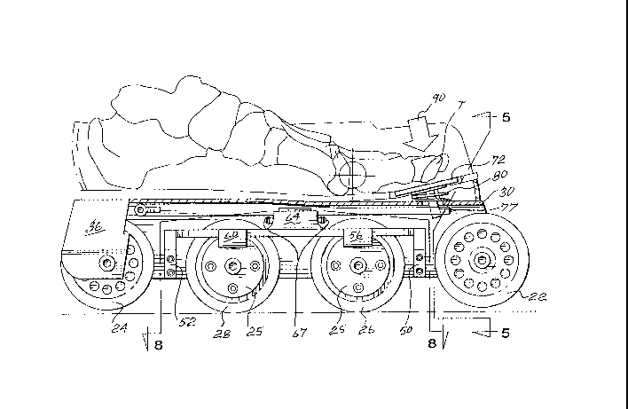
Referring to the drawings in greater detail and by
reference characters thereto, there is illustrated in Figure
1 an in-line roller skate or generally designated by
reference numeral 10 and which includes a conventional type
of boot 12 having a boot body 14, a boot sole 20, a tongue
16 and straps 18. The above is all a substantially
conventional construction.
In-line skate 10 has a front wheel 22, a rear wheel
24, and a pair of center wheels 26 and 28. Center wheels 26
and 28 include a disk member 25 mounted on both sides (only
one shown). A wheel mounting frame includes a base 32
secured to the bottom of boot sole 20 and a pair of
21~4399
downwardly extending side walls 34 and 36. Extending
between walls 34 and 36 are a plurality of axles 38 for
mounting wheels 22, 24, 26 and 28.
As shown in Figure 3, there is provided a brake
assembly generally designated by reference numeral 40 which
is enclosed within the wheel mounting frame. Brake assembly
40 is substantially symmetrical about its longitudinal axis
and detailed reference will be made to one side of the
assembly with similar components on the other side being
designated, where appropriate, by like reference numerals
using a prime.
There is provided a U-shaped member comprising
longitudinally extending element 44 having at each end
thereof, an end arm 46 and 48. At the front, adjacent end
arm 46 there is provided a mounting member 50 which extends
between side walls 34 and 36 and is suitably secured thereto
by screws 55 received in screw threaded apertures 54.
Mounting member 50 is located to extend between front
wheel 22 and center wheel 26.
Mounting member 50 also is adapted to mount arms 46,
46' and thus has an aperture 57 (Figure 3) for receiving a
screw 59 (Figure 8). At the rear end of the skate, a
similar mounting member 52 is likewise adapted to receive
and mount end arms 48, 48' and is secured to side walls 34,
36 by screws 53.
Mounted on longitudinal elements 44 and 44' are
brake pad holders 56, 56' each of which have a brake pad 58,
2154399
58' respectively. A similar brake pad holder 60 with an
associated brake pad is provided adjacent center
wheel 28.
Longitudinal elements 44 and 44' each have an
upwardly extending portion 64, 64' which in turn has a cam
surface 65, 65' associated therewith. Mounted intermediate
cam surfaces 65, 65' is a cam member 66. Portions 64, 64'
are secured together by a pair of spring members 67.
Extending longitudinally of the skate is an
interconnecting member 68 which is connected to side walls
34 and 36 by transversely extending arm portions 70 and 70'
at the rear end of interconnecting member 68.
At the forward end of force interconnecting member
68, there is provided a pressure plate 72 which is secured
to interconnecting member 68 by means of a vertical
post 76. Post 76 passes through an aperture within
interconnecting member 68 and is held in a desired position
by means of a set screw 77.
As may best be seen in Figure 4, pressure plate 72
is mounted within boot sole 20 and a compression spring 80
is mounted between the bottom of pressure plate 72 and base
32 of wheel mounting frame 30.
In operation, when it is desired to brake or exert a
retarding force on the wheels, pressure by one or more toes
T exert a force as indicated by arrow 90 on pressure plate
72 and will cause a downward movement to be exerted on
interconnecting arm 68. This in turn will cause camming
-- 10 --
2154~
member 66 to act on camming surfaces 65, 65' to overcome the
normal biasing force exerted by springs 67. Accordingly,
longitudinal arms 44, 44' will pivot to cause brake pads 58
and its companion (not shown) to engage with the disks 25 on
the sides of center wheels 26 and 28.
During normal operation, the toe or toes of the
skater will not exert enough pressure to overcome the force
on the spring. However, when desired, sufficient pressure
can be exerted to overcome the spring pressure and thereby
activate the brakes. As will be appreciated, the pressure
required can be adjusted by means of set screw 77.
It will be seen that one could maintain the force on
pressure plate 72 when walking or forming other maneuvers
such as climbing stairs. This would overcome many of the
problems otherwise associated with such movement.
In an alternative embodiment illustrated in
Figure 7A, a single brake is utilized. In this embodiment,
similar reference numerals in the lOO's are utilized. As
will be seen, interconnecting member 168 is adapted to press
downwardly on cam member 166 which will in turn transmit
force through camming member 166 and member 164 to cause
brake pad 158 to be applied against disc 125 mounted on the
side of wheel 126.
It will be understood that the above described
embodiments are for purposes of illustration only and that
changes and modifications may be made thereto without
departing from the spirit and scope of the invention.