Sélection de la langue

Search

Sommaire du brevet 2154531 

Énoncé de désistement de responsabilité concernant l'information provenant de tiers

Une partie des informations de ce site Web a été fournie par des sources externes. Le gouvernement du Canada n'assume aucune responsabilité concernant la précision, l'actualité ou la fiabilité des informations fournies par les sources externes. Les utilisateurs qui désirent employer cette information devraient consulter directement la source des informations. Le contenu fourni par les sources externes n'est pas assujetti aux exigences sur les langues officielles, la protection des renseignements personnels et l'accessibilité.

Disponibilité de l'Abrégé et des Revendications

L'apparition de différences dans le texte et l'image des Revendications et de l'Abrégé dépend du moment auquel le document est publié. Les textes des Revendications et de l'Abrégé sont affichés :

  • lorsque la demande peut être examinée par le public;
  • lorsque le brevet est émis (délivrance).
(12) Demande de brevet: (11) CA 2154531
(54) Titre français: CONTACTEUR DE PROXIMITE A SURFACE CERAMIQUE, ET METHODE DE FABRICATION CONNEXE
(54) Titre anglais: PROXIMITY SWITCH WITH CERAMIC SURFACE AND METHOD FOR ITS MANUFACTURE
Statut: Réputée abandonnée et au-delà du délai pour le rétablissement - en attente de la réponse à l’avis de communication rejetée
Données bibliographiques
(51) Classification internationale des brevets (CIB):
  • H01H 09/04 (2006.01)
  • B23P 11/02 (2006.01)
  • H03K 17/95 (2006.01)
(72) Inventeurs :
  • HEIMLICHER, PETER (Suisse)
(73) Titulaires :
  • OPTOSYS SA
(71) Demandeurs :
  • OPTOSYS SA (Suisse)
(74) Agent: SMART & BIGGAR LP
(74) Co-agent:
(45) Délivré:
(22) Date de dépôt: 1995-07-24
(41) Mise à la disponibilité du public: 1996-01-27
Licence disponible: S.O.
Cédé au domaine public: S.O.
(25) Langue des documents déposés: Anglais

Traité de coopération en matière de brevets (PCT): Non

(30) Données de priorité de la demande:
Numéro de la demande Pays / territoire Date
02 358/94-0 (Suisse) 1994-07-26

Abrégés

Abrégé anglais


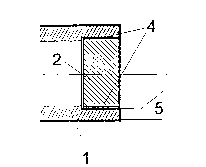
A ceramic portion (2) is inserted in the front
side of the housing envelope (1) by shrinking. At the
joint resp. the junction (4) of these parts, a sealing
layer, preferably a galvanized copper layer, is ap-
plied which ensures a connection which under the
resulting pressure is impermeable to gases and humid-
ity. The ceramic portion (2) is exposed to a strong
radial pressure prestress with the result that the
tensile stress of the ceramic portion is reduced and
thus the pressure resistance thereof is increased
under the effect of an axially acting external pres-
sure.

Revendications

Note : Les revendications sont présentées dans la langue officielle dans laquelle elles ont été soumises.


Claims
1. A proximity switch comprising a metallic
housing envelope (1) in which a ceramic portion (2) is
inserted as a closure, wherein the ceramic portion (2)
is inserted in the housing envelope (1) by shrinking,
and wherein a sealing material (7) disposed between
said housing envelope (1) and said ceramic portion (2)
provides a seal which is impermeable to gases and liq-
uids.
2. The proximity switch of claim 1, wherein a
ductile material such as copper serves as a sealing
material (7).
3. The proximity switch of claim 1 (or 2),
wherein the sealing material (7) is applied to one or
both of the contact surfaces between the housing en-
velope (1) and the ceramic portion (2) e.g. by evapo-
ration or galvanic metallizing.
4. The proximity switch of (any one of) claim(s)
1 (to 3), wherein by a suitable design of the housing
envelope (1) or of the ceramic portion (2) such as
grooving, the surface pressure is increased and regu-
larly or irregularly distributed over said junction
(4).
5. A method for the manufacture of a proximity
switch according to claim 1, wherein the sealing con-
nection of the ceramic portion (2) to the housing en-
velope (1) is obtained by inserting said ceramic por-
tion, which at ambient temperature has a greater dia-
meter than the corresponding seat (3) in the housing
- 7 -

envelope (1), into the housing envelope after the lat-
ter has been heated, said ceramic portion (2) being
positively maintained due to the shrinking of said
housing envelope when the latter has cooled off, in
such a manner that a gas- and liquid-tight seal be-
tween the housing envelope and the ceramic portion is
obtained due to a surface coating of the housing en-
velope in the area of the junction (4).
6. The method of claim 5, wherein the surface
coating is obtained by applying a soft, ductile metal
coat (7), the metal coat possibly being applied by
galvanic means and possibly consisting of copper.
7. The method of claim 5 (or 6), wherein the
surface coating is applied to the entire surface of
the housing envelope.
8. The method of claim 7, wherein the surface
coating outside the junction is again removed as soon
as the connection is completed.
9. The method of (one of) claim(s) 5 (to 8, in
particular), wherein the resistance of the ceramic
portion (2) to external pressure (P) is increased by
the creation of a higher pressure prestress (F0) of
the latter than would be necessary for its fastening
and sealing.
10. The method of claim 9, wherein the surface
pressure in the area of the junction (4) is so dimen-
sioned that the limit of elasticity of the housing en-
velope material is exceeded in that area.
- 8 -

Description

Note : Les descriptions sont présentées dans la langue officielle dans laquelle elles ont été soumises.

215~531
PROXIMITY SWITCH WITH CERAMIC FRONT SURFACE AND METHOD
FOR ITS MANUFACTURE
Backqround of the Invention
According to their destination, proximity
switches of different technologies (inductive, capaci-
tive, ultrasonic, magnetic and others) are subject to
high stresses due to environmental influences. The
resulting need for protection of the structural com-
ponents contained therein is an important requirement.
Consequently, the currently available apparatus are
mostly complete with casings of metal or high-quality
plastics which are generally filled with casting resin
in addition.
In practice, however, there are applications
where these measures are insufficient, e.g. in the
presence of aggressive chemicals, high temperatures
and pressures, as well as in the foodstuff industry.
In these cases, housings of special steel are used.
In this context, the active surface is of special in-
terest since in general, it must be made of an elec-
trically insulating material. Materials of choice for
this purpose are ceramic materials.
The problem involving difficulties consists in
the gas- and liquid-tight junction between the ceramic
active surface and the housing, which must fulfill
high requirements. Not only should it be tight, but
also pressure-resistant, vibration-resistant, and ap-
plicable in a wide temperature range. Furthermore, a
very high resistance to temperature cycles is re-
quired. An excellent chemical stability is indis-
(MS/as 02.06.95)

21~531
pensable. All these properties must be conserved dur-
ing the full lifetime of the product, which typically
exceeds ten years. In addition, the manufacturing
method should be simple, safe, and first of all, eco-
nomical.
Another problem is the fact that the active sur-
face should be as thin as possible, for the useful
switching distance of the sensor is naturally reduced
by its thickness. This is particularly important if
the appliance is intended for high external pressures.
A number of solutions to the stated problem are
known, all of which involve essential inconvenients,
however. The safest method consits in metallizing the
ceramic portion in the area of the connecting surface
and then soldering it tightly to the housing. The ob-
tained result is very good, but the manufacturing pro-
cess is complicated and thus expensive. Another
method consists in cementing the parts with a suitable
cement. Although this is economical, it is unsafe,
especially under higher temperatures and in an aggres-
sive environment.
Summary of the Invention
The present invention solves the mentioned prob-
lems in a simple and economical manner by means of a
proximity switch wherein the ceramic portion is in-
serted in the housing envelope by shrinking, and
wherein a sealing material disposed between said hous-
ing envelope and said ceramic portion provides a seal
which is impermeable to gases and liquids; and by a
manufacturing method wherein the sealing connection of
(MS/as 02.06.95)

2154531
the ceramic portion to the housing envelope is obtain-
ed by inserting said ceramic portion, which at ambient
temperature has a greater diameter than the corre-
sponding seat in the housing envelope, into the hous-
ing envelope after the latter has been heated, saidceramic portion being positively maintained due to the
shrinking of said housing envelope when the latter has
cooled off, in such a manner that a gas- and liquid-
tight seal between the housing envelope and the cera-
mic portion is obtained due to a surface coating ofthe housing envelope in the area of the junction.
Brief Description of the Drawinqs
The invention is explained in more detail herein-
after with reference to an embodiment which is illu-
strated in the drawing.
Figs. 1 and 2 show lateral resp. front views ofthe parts to be connected to the housing;
Fig. 3 shows the parts which are connected by
shrinking;
Fig. 4 shows an alternative embodiment having a
surface structure increasing the contact pressure;
Fig. 5 shows a sealing layer; and
Fig. 6 shows the forces acting upon the inserted
ceramic part.
(MS/as 02.06.95)

2~ S~531
Detailed DescriPtion of the Invention
The invention starts from a method which is being
used for other purposes and known Per se, and which
consists in shrinking a metal portion onto a corre-
sponding internal portion of a ceramics material. Ex-
amples thereof are found in DE-A-40 32 803, DE-A- 40
21 259, EP-A-0 197 890 and DE-C-35 45 135. For this
purpose, the diameter of ceramics portion 2 is made
slightly greater than that of the corresponding seat 3
in housing envelope 1. In order to insert ceramics
portion 2 into housing envelope 1, the latter is heat-
ed to a temperature of e.g. 800 C in the area of seat
3. The heating may be effected simply and quickly in
a known manner by inductive means. The housing enve-
lope 1 is thereby expanded (the linear dilatation co-
efficient being approx. 12 x 1 o-6 / oc~ for example,
in the case of V2A)o The ceramics portion 2, which is
not heated and therefore not expanded, is now inserted
without any expenditure of force into the correspond-
ing seat 3 of housing envelope 1. The supply of en-
ergy is then interrupted, whereupon the entire ar-
rangement cools off. On account of the resulting
shrinking of housing 1, a firm connection between
housing 1 and ceramics portion 2 is obtained without
any further operations.
The connection thus obtained may be characterized
by intense compression, but it is generally not gas-
and liquid-tight. According to the invention, the
surface of the metal housing envelope 1 is therefore
previously treated, i.e. typically through the ap-
plication of a suitable layer 7 (Fig. 5) of a ductile
metal, e.g. copper, having a thickness in the order of
-- 4
(MS/as 02.06.95)

215~531
some 10 ~m, in the area of the junction 4 (Fig. 4).
Thus, an excellent seal results if the coat thickness
and the surface pressure are suitably dimensioned. It
is most advantageous to first treat the entire housing
envelope and to remove, as desired, the portions of
the coat that are no longer required after the connec-
tion has been established, the coat being conserved in
the area of the junction due to the gas- and liquid-
tight seal.
By an appropriate choice of the materials and of
the wall thickness 5 of the housing in the area of
seat 3, the desired surface pressure can be adjusted
in a wide range. In addition, said range can be fur-
ther enlarged by a corresponding design of contact
surface 6. An example thereof is shown in Fig. 4,
where annular grooves 6 are provided in contact sur-
face 6.
Another advantage results from the prestress of
ceramic portion 2 which can bear a higher external
pressure P at a given shape than would be possible
without such a prestress (Fig. 6). This takes ad-
vantage of the fact that ceramic materials may be ex-
posed to substantially higher pressures than tensions.
The prestress caused by the pressure resulting from
the shrinking of the metal housing portion creates the
pressure F0 in ceramic portion 2 (Fig. 6). An ex-
ternal pressure P creates pressures und tensions F1.
Due to their superposition, the pressures and tensions
F1 created by external pressure P are increased (pres-
sures) resp. reduced (tensions) by the amount of thepressure F0. The resulting tensions, whose sum is
reduced, thus allow a higher stress of ceramic portion
(MS/as 02.06.95)

2154531
2 by external pressure P than would be allowable
without the mentioned prestress. Advantageously, the
junction is so designed that the limit of elasticity
of the housing material is exceeded in the area of the
contact surface 4 after it has cooled off. This al-
lows to obtain a prestress which is largely indepen-
dent of machining tolerances.
(MS/as 02.06.95)

Dessin représentatif
Une figure unique qui représente un dessin illustrant l'invention.
États administratifs

2024-08-01 : Dans le cadre de la transition vers les Brevets de nouvelle génération (BNG), la base de données sur les brevets canadiens (BDBC) contient désormais un Historique d'événement plus détaillé, qui reproduit le Journal des événements de notre nouvelle solution interne.

Veuillez noter que les événements débutant par « Inactive : » se réfèrent à des événements qui ne sont plus utilisés dans notre nouvelle solution interne.

Pour une meilleure compréhension de l'état de la demande ou brevet qui figure sur cette page, la rubrique Mise en garde , et les descriptions de Brevet , Historique d'événement , Taxes périodiques et Historique des paiements devraient être consultées.

Historique d'événement

Description Date
Inactive : CIB de MCD 2006-03-11
Le délai pour l'annulation est expiré 2003-07-24
Demande non rétablie avant l'échéance 2003-07-24
Réputée abandonnée - omission de répondre à un avis sur les taxes pour le maintien en état 2002-07-24
Inactive : Abandon.-RE+surtaxe impayées-Corr envoyée 2002-07-24
Demande publiée (accessible au public) 1996-01-27

Historique d'abandonnement

Date d'abandonnement Raison Date de rétablissement
2002-07-24

Taxes périodiques

Le dernier paiement a été reçu le 2001-06-19

Avis : Si le paiement en totalité n'a pas été reçu au plus tard à la date indiquée, une taxe supplémentaire peut être imposée, soit une des taxes suivantes :

  • taxe de rétablissement ;
  • taxe pour paiement en souffrance ; ou
  • taxe additionnelle pour le renversement d'une péremption réputée.

Les taxes sur les brevets sont ajustées au 1er janvier de chaque année. Les montants ci-dessus sont les montants actuels s'ils sont reçus au plus tard le 31 décembre de l'année en cours.
Veuillez vous référer à la page web des taxes sur les brevets de l'OPIC pour voir tous les montants actuels des taxes.

Historique des taxes

Type de taxes Anniversaire Échéance Date payée
TM (demande, 2e anniv.) - générale 02 1997-07-24 1997-06-06
TM (demande, 3e anniv.) - générale 03 1998-07-24 1998-06-30
TM (demande, 4e anniv.) - générale 04 1999-07-26 1999-07-06
TM (demande, 5e anniv.) - générale 05 2000-07-24 2000-07-07
TM (demande, 6e anniv.) - générale 06 2001-07-24 2001-06-19
Titulaires au dossier

Les titulaires actuels et antérieures au dossier sont affichés en ordre alphabétique.

Titulaires actuels au dossier
OPTOSYS SA
Titulaires antérieures au dossier
PETER HEIMLICHER
Les propriétaires antérieurs qui ne figurent pas dans la liste des « Propriétaires au dossier » apparaîtront dans d'autres documents au dossier.
Documents

Pour visionner les fichiers sélectionnés, entrer le code reCAPTCHA :


Pour visualiser une image, cliquer sur un lien dans la colonne description du document. Pour télécharger l'image (les images), cliquer l'une ou plusieurs cases à cocher dans la première colonne et ensuite cliquer sur le bouton "Télécharger sélection en format PDF (archive Zip)" ou le bouton "Télécharger sélection (en un fichier PDF fusionné)".

Liste des documents de brevet publiés et non publiés sur la BDBC .

Si vous avez des difficultés à accéder au contenu, veuillez communiquer avec le Centre de services à la clientèle au 1-866-997-1936, ou envoyer un courriel au Centre de service à la clientèle de l'OPIC.


Description du
Document 
Date
(aaaa-mm-jj) 
Nombre de pages   Taille de l'image (Ko) 
Dessin représentatif 1998-04-15 1 4
Description 1996-01-26 6 196
Abrégé 1996-01-26 1 17
Revendications 1996-01-26 2 68
Dessins 1996-01-26 1 21
Rappel - requête d'examen 2002-03-25 1 119
Courtoisie - Lettre d'abandon (taxe de maintien en état) 2002-08-20 1 182
Courtoisie - Lettre d'abandon (requête d'examen) 2002-10-01 1 170
Courtoisie - Lettre du bureau 1995-10-12 1 22