Note : Les descriptions sont présentées dans la langue officielle dans laquelle elles ont été soumises.
wo 94/18369 215 5 ~ 0 7 PCT/US94/00592
METHOD AND APPARATUS FOR MOLDING A PLASTIC
WASHING MACHINE BASKET
BACKGROUND OF THE INVENTION
1. Field of the Invention
The present invention pertains to the art of washing m~hin~s and,
more particularly, to a plastic washing machine basket along with a method and
apparatus for making the same.
2. Discussion of the Prior Art
Washing m~hine baskets are generally formed from metal and include
spaced holes in both a base wall and an annular sidewall thereof. In accordance with
s the prior art, normally these holes are pelrol~ted subsequent or prior to shaping the
metal basket. This multi-step manufacturing method is costly and time consuming.
Wo 9~/18369 . 1 ~ PCT/US94/00592 --
21~50~7 2
It has also heretofore been proposed to forrn a washing m~chine basket
from a plastic material. Attempts have been made to mold such plastic washing
machine baskets in an apparatus which would simultaneously form the desired
apertures in the base wall and annular sidewall of the basket. However, such attempts
5 have proved l-n~lccescful and have resulted in plastic baskets having numerous knit
lines formed on the inner surface of the basket. Knit lines cause reduced structural
integrity and visually indicate defects. Alternatively, it has also been proposed to
mold a plastic washing m~chine basket as a unitary structure and then perforate the
holes during a subsequent m~nllf~cturing step. This method leaves burrs and sharp
10 edges that would result in damage to garments washed in the basket. Again, this need
for multiple manufacturing steps is undesirable and results in increased m~m-f~tllring
costs.
Therefore, there exists a need in the art for a method and apparatus for
molding a plastic washing m~hine basket with holes in the base wall and annular
sidewall thereof, without forming undesirable knit lines, in a single manuf~ctllring
step.
SUMMARY OF T~ INVENTION
It is an object of the present invention to provide a plastic washing
m~ hine basket which can be molded in a single manufacturing step with holes formed
20 in both a base wall and an annular sidewall of the basket without llndesir~hle knit
lines on the inner surface of the basket.
215~007
Wo 94118369 PCT/US94/00592
It is a further object of the present invention to provide a method and
an apparatus for molding a plastic washing machine basket without knit lines on the
inner surface thereof while forming the basket with spaced holes in both a base wall
and an annular sidewall thereof.
These and other objects of the present invention are accomplished by
providing a molding apparatus comprising a mold core which is fixed at one end and
includes teardrop-shaped projections spaced about an outer periphery thereof, a
plurality of cavity sidewall members being movable between an open mold position,
in which the cavity sidewall members have been shifted at a predetermined angle
away from the mold core, and a closed mold position, in which the cavity sidewall
members extend about the outer periphery of the mold core with a first predetermined
space therebetween, and a cavity cover member extending about the second end of the
mold core with a second predetermined space therebetween and abutting the cavity
sidewall members when in a closed mold position but being spaced from the cavity
sidewall members when in an open mold position. The cavity sidewall members carry
core pins having terminal ends which project toward and abut the teardrop-shaped
projections of the mold core when the cavity sidewall members are in the closed mold
position.
By this arrangement, when a plastic material is injected into the first
20 and second predetermined spaces, the plastic m~t~.ri~l will flow about the core pins
and the projections so as to form a plastic washing machine basket having an annular
sidewall exten~ling upward from a peripheral portion of a base wall wherein the
Wo 94/18369 ; ; PCT/US94/00592 --
2155007
sidewall will have inner and outer surfaces with spaced apertures extending
therethrough and teardrop-shaped grooves extending from the apertures. After
cooling of the plastic material, the various core pins are used to remove the molded
plastic washing machine basket from the mold core during an ejection process by
S shifting the basket relative to the mold core through the interengagement of the core
pins with the apertures formed in the sidewall of the basket. A stripper ring and an
ejection system, are also provided to aid in removing the molded basket from the
mold core.
Other objects, features and advantages of the invention will become
10 more readily apparent from the following detailed description of preferred
embo liment~ thereof when taken in conjunction with the drawings wherein like
reference characters refer to corresponding parts in the several views.
BRIEF DESCRIPIION OF THE DRAWINGS
Figure 1 depicts a perspective view of the plastic washing m~hine
15 basket of the invention.
Figure 2 depicts a partial, cross-sectional view of the plastic washing
m~hine basket of Figure 1.
Figure 3 is a cross-sectional view of an apparatus for molding the
plastic washing m~ehine basket of Figure 1 in a closed mold position.
WO 94/18369 215 ~ O 0 7 PCT/US94/00592
Figure 4 depicts a cross-sectional view of the molding apparatus shown
in Figure 3 in an open mold position.
Figure 5 is a partial, perspective view of the molding apparatus shown
in Figures 3 and 4.
DETAILED DESCRIPTION OF THE INVENTION
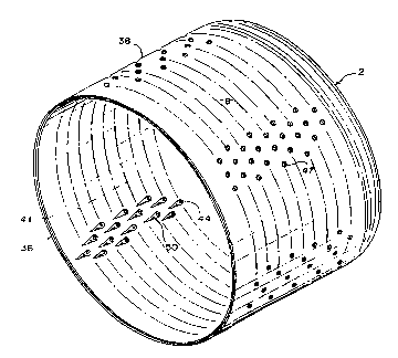
The plastic washing m~hine basket 2 of the invention will be explained
with reference to Figures 1 and 2. Basket 2 includes a base wall 5 and an annular
sidewall 8 extending from a peripheral portion 10 of base wall 5. Basket 2 further
includes a mounting portion 11 having a first annular flange 14 projecting into the
interior of basket 2 from an inner surface 16 of base wall 5 and a second annular
flange 18 which eYt~ntlc away from an outer surface 19 of base wall 5. First annular
flange 14 defines a central throughhole 21 through which an output shaft of a drive
train including an electric drive motor or the like (not shown) may extend, as is
known in the art. Radially between first annular flange 14 and second annular flange
1~ 18, outer surface 19 of base wall 5 defines a circular mounting flat 23 having spaced
mounting holes 25 extçn~ling therethrough. Mounting flat 23 is adapted to securebasket 2 to a drive train carried support structure, such as a drive plate (not shown),
by any type of f~ctçning means known in the art and extending through mounting
holes 25.
Outer surface 19 of base wall 5 is formed with a plurality of spaced
lower ribs 28 which extend from second annular flange 18 and merge with outer
WO 9~/18369 PCT/US94/00592 --
215~07
- surface 19 adjacent peripheral portion 10. In a similar manner, a plurality of spaced
upper ribs 31 extend along inner surface 16 of base wall 5 from first annular flange
14. Ribs 28 and 31 provide additional structural rigidity for mounting portion 11.
Base wall 5 is also formed with a plurality of drain holes 34 which extend through
inner and outer surfaces 16, 19 of base wall 5.
As previously stated, annular sidewall 8 extends from peripheral portion
10 of base wall 5 to a terminal edge 36. Sidewall 8 is defined by an outside surface
38 and an inside surface 41 through which a plurality of apertures 44 extend.
Apertures 44 are spaced along the length of sidewall 8 in ~ltern~ting rows, as
generally depicted in both Figures 1 and 2. For the sake of clarity in these figures,
apertures 44 have not been shown to extend entirely around the circumference of
sidewall 8. However, in the preferred embodiment, apertures 44 are provided around
the entire circumference of sidewall 8 and are slightly and progressively reduced in
diameter from adjacent base wall 5 toward terminal edge 36. At outside surface 38,
apertures 44 are beveled at 47. In addition, inside surface 41 of sidewall 8 is formed
with teardrop-shaped grooves 50 which extend about apertures 44. Teardrop-shapedgrooves 50 generally taper along their length, in both width and depth, from base wall
5 toward terminal edge 36 such that apertures 44 are located in subst~nti~lly the
widest and deepest portions of teardrop-shaped grooves 50. Finally, terminal edge
36 of sidewall 8 is provided with an outer annular notch 52 for the reasons which will
be more fully discussed below.
wo 94/18369 2 1 5 ~i O 0 7 PCT/US94/00592
Reference will now be made to Figures 3-5 in describing an apparatus
60 for molding plastic washing machine basket 2. Apparatus 60 comprises a
mounting plate 64 ~o which a plurality of support rails 67 are secured. A core
support block 70 having a central throughhole 73 is fixedly mounted to ~u~o,l rails
S 67. The upper portion of core support block 70 includes a base surface 78, a lower
plateau 80, an intermeAi~tP plateau 83 and an upper plateau 86. A mold core 90 is
secured to base surface 78 of core support block 70. Mold core 90 includes a core
insert 93. The molding apparatus 60 further includes a stripper ring 96 which rests
upon lower plateau 80 of core support block 70, a plurality of cavity sidewall
members 99 which extend about the periphery of mold core 90 with a first space
therebetween and a cavity cover member 102, which has secured thereto a cover
insert 105, eYten~iing about an end of mold core 90 with a second space therebetween
and abutting cavity sidewall members 99 when in a closed mold position. Cavity
cover member 102 and cover insert 105 include an aligned throughhole (not labeled)
within which an injection tube 110 is secured. Injection tube 110 includes an injection
passage 113 which terrnin~tPs in a nozzle 116 for introducing a flow of plastic
m~tPri~l within the spaces between mold core 90 and both cavity cover member 102and cavity sidewall members 99. The particular structure and interrelationship of the
elements which comprise molding apparatus 60 as briefly discussed above will nowbe individually described in detail below.
Mold core 90 includes a trough portion 121 (see Figure 4) and a crest
portion 123. Mold core 90 is formed with a plurality of pins 125 which extend from
trough portion 121 and a plurality of pins 127 which extend from crest portion 123.
Wo 94/18369 PCT/US94/00592--
2 ~L S ~ 8
Mold core 90 is further provided with a central bore 130 and a plurality of teardrop-
shaped projections 132 which are spaced subst~nti~lly about the entire outer periphery
of mold core 90. Teardrop-shaped projections 132 define the length, width and depth
of teardrop-shaped grooves 50 in plastic washing machine basket 2 discussed above.
T oc~t~i in central through hole 73 is a hydraulic actuator 135
comprising a cylinder 138 and an ejector rod 140 which extends through bore 130 and
terrnin~tes in a plate 142. Although not detailed in the drawings, hydraulic actuator
135 is constructed in a manner known in the art wherein ejector rod 140 carries a
piston at the end opposite terminal plate 142 such that the piston can move within
cylinder 138 and defines upper and lower chambers on opposite sides thereof. A first
hydraulic line 145 extends into the upper chamber in hydraulic actuator 135 while a
second hydraulic line 146 extends into the lower charnber. By adjusting the supply
of hydraulic fluid through first and second hydraulic lines 145 and 146, ejector rod
140 can be e~t~nde~ or retracted relative to cylinder 138. Upper and lower limitswitches 149 and 150 are provided to indicate upper and lower displacement limits for
the piston within cylinder 138. In the L~fer~ d embodiment, cylinder 138 of
hydraulic actuator 135 is secured to a plate 154 which is movable between lower and
upper limits as l~lesented in Figures 3 and 4 respectively. The movement of plate
154 will be more fully discussed below.
Stripper ring 96 includes a tapered inner wall 162 which is adapted to
conform to and seal against a tapered outer surface 163 of mold core 90 when
molding apparatus 60 is in the closed mold position depicted in Figure 3. Stripper
wo g~/18369 215 5 0 0 7 PCTIUS94/00592
ring 96 is adapted to be shifted between the position shown in Figure 3 to that shown
in Figure 4 so as to aid in ejecting plastic washing m~hine 2 from molding appaldlus
60. In order to shift the ~Llipper ring 96, a plurality of rods 171 are fixedly secured
between stripper ring 96 and movable plate 154 such that when movable plate 154 is
shifted from the position shown in Figure 3 to the position shown in Figure 4 by any
means known in the art (not shown), stripper ring 96 will be lifted from lower plateau
80 of support block 70.
As previously stated, cavity sidewall members 99 extend about the
periphery of core 90 and are mounted upon stripper ring 96. In the ~lc;fe.l~d
embodiment, as best shown in Figure 5, four such cavity sidewall members 99 are
utili~ed. Adjacent ~Llippel ring 96, each cavity sidewall member 99 is provided with
a groove 175 within which a guide pin 177, secured to stripper ring 96 by means of
a plate 179, extends. Grooves 175 extend laterally within cavity sidewall members
99, as shown in Figures 3 and 4. In the ~l~felled embo~iimPnt, both the guide pins
177 and grooves 175 are formed from a wear resi~t~nt and low friction m~t~?ri~l so
as to permit cavity sidewall members 99 to slide relative to ~Llipper ring 96 in a
laterally outward direction as shown in Figures 3 and 4. Molding appardlus 60
further includes a means to autom~tic~lly shift and guide cavity sidewall members 99
relative to stripper ring 96 upon lifting of stripper ring 96 from lower plateau 80.
20 This guide arrangement not only includes grooves 175 and guide pins 177 but further
includes angled bores 181 (see Figure 3) extentling through cavity sidewall members
99 within which are received guide rods 184 secured to core support block 70 at 186.
Therefore, by this arrangement, when ~lipper ring 96 is lifted from the position
Wo 94/183 PCT/US94/00592--
2 1 ~ o
shown in Figure 3 to the position shown in Figure 4, cavity sidewall members 99 will
also be lifted and will be forced to shift laterally outwardly due to the presence of
guide rods 184 in angled bores 181.
Each cavity sidewall member 99 further incl~ldes an inner plate 188
fixedly secured thereto. Inner plate 188 carries numerous spaced core pins 191 (540
core pins being utilized in the ple~lled embodiment of the invention). Core pins 191
include beveled tips 193 each of which is adapted to engage a corresponding ~eaLdlUp-
shaped projection l32 formed about the periphery of mold core 90 when molding
a~3paldt,ls 60is in its closed mold position. In the closed mold position, a lower tier
198 of the cavity sidewall members 99 rests upon ~ per ring 96 and intermeAi~t~oplateau 83 of core support block 70 while an upper tier 199 of cavity sidewall
members 99 rests upon upper plateau 86 of core support block 70.
A more ~et~iled description of cavity cover member 102 will now be
provided. Cavity cover member 102 includes an annular flange portion 202 which
is adapted to abut cavity sidewall members 99 when molding apparatus 60 is in the
closed mold position as shown in Figure 3 and which is spaced from cavity sidewall
members 99 when molding a~a,~us 60 is in an open mold position as depicted in
Figure 4. It should be readily recognized that molcling appa~Ltus 60 can be changed
between its open and closed mold positions by linearly shifting either cavity cover
member 102 relative to mold core 90 or vice versa by any means known in the art
(not shown) such as hydraulic or pneumatic linear actuators while shifting the cavity
sidewall members 99 away from mold core 90 at a predetermined angle as discussed
WO 94/18369 21~ ~ O 0 7 PCT/US94/OQ592
11
above. In the preferred embodiment, mold core 90 is shifted relative to cavity cover
member 102. In the closed mold position, bores 205 formed in cavity cover member102 extend about guide rods 184 to subst~nti~lly close molding appaldt-ls 60 andprevent shifting of cavity sidewall members 99. Cover insert 105 of cavity coverS member 102 includes numerous pins 208 which are adapted to abut respective pins
127 forrned on crest portion 123 of mold core 90 along with hollow pins 210 for
receiving pins 125 on trough portion 121 when molding a~pal~tlls 60 is in the close
mold position.
The particular manner in which molding apparatus 60 is used to form
plastic washing machine basket 2 along with the unique method of removing plastic
washing m~chine basket from mold core 90 will now be explained. As previously
stated, molding a~aldLus 60 is depicted in a closed mold position in Figure 3. In this
position, a plastic m~teri~l may be injected through passage 113 and nozzle 116 into
the spaced defined between mold core 90 and both cover insert lOS of cavity cover
lS member 102 and cavity sidewall members 99. The interconnection between pins 127,
208 and 125, 210 respectively will prevent the plastic m~t~ri~l from flowing into these
areas to form mounting holes 25 and drain holes 34 in basket 2. The plastic m~tt-ri~l
will then continue to flow over crest portion 123 of mold core 90 and between mold
core 90 and cavity sidewall members 99. At this point, the plastic m~t~ri~l will flow
about the beveled tips 193 of core pins 191, which extend subst~nti~lly perpendicular
to the longitu~in~l axis of mold core 90, and the ~ drop-shaped projections 132 in
order to form beveled apertures 44 and the teardrop-shaped grooves SO in basket 2.
It is important to note that the teardrop-shaped projections 132 permit the plastic
Wo g~/18369 PCT/US94/00592--
21 ~5~7 12
material to flow around core pins 191 wIthout creating knit lines which would
inherently be formed without the presence of the teardrop-shaped projections 132.
Projections 132 actually create a wind tunnel or turbulence effect for the plastic
material which elimin~tPs the knit lines associated with prior known molding
5 arrangements and thereby basket 2 can be formed with a smooth inner surface 41.
Once the flow of plastic m~tPri~l is cut off, the plastic m~teri~l is given
a s~lfficient amount of time to cool. Cooling of the plastic m~tPri~l along with
molding apparatus 60 is preferably enhanced by providing various cooling lines 214-
222 which extend throughout molding appa~dLLIs 60 in a manner known in the art.
10 Various ~tt~f~hmPnt plates, such as that in~ tPs~ at 123, may be utilized to
interconnect various tubes and passages between, for example, cavity cover member
102 and cover insert 105 and mold core 90 and mold insert 93 with O-rings 224
therebetween. As the use of such cooling lines and ~tt~chmPnt methods therefor are
widely known in the art and not considered part of the present invention, these will
15 not be further described herein.
Molding of basket 2 with a smooth inner surface 41 creates a problem
in removing basket 2 since the basket 2 will tend to adhere to the outer peripheral
surface of mold core 90. The use of an injection rod and a stripper ring to remove
a molded article from a mold core is known in the art. However, these two element~
20 alone could not sufficiently remove basket 2 from mold core 90 without severely
d~m~ging basket 2. To remedy this problem, during the initial ejection phase of
basket 2, cavity cover member 102 is shifted away from cavity sidewall members 99
~ WO 94/18369 2 i 5 ~ () O 7 PCT/US94/00592
13
such that bores 205 are separated from guide rods 184. Stripper ring 96, which
engages notch 52 provided about the terminal edge 36 of basket 2, is shifted upward
by means of rods 171. Sincecavity sidewall members 99 are ~u~ollcd upon stripper
96, cavity sidewall members 99 will also be shifted relative to mold core 90. As
5 previously stated, the position of cavity sidewall members 99 relative to mold core 90
during shifting of stripper ring 96 is determined based on the particular guiding
arrangement provided. More specifically, as ~llip~er ring 96 is lifted off lower
plateau 80, cavity sidewall members 99 will be lifted and shifted laterally relative to
mold core 90. During the initial lifting of stripper ring 96, each of the core pins 191
10 will be engaged within a respective apcl~ulc 44 of basket 2 to provide a lifting force
about the entire periphery of mold core 90. This lifting force is aided by both the
ejection rod 140 and stripper ring 96 and enables basket 2 to be removed from mold
core 90 without being damaged. Air lines (not shown), along with additional ejector
rods 250 (see Figures 3-5) which are secured to movable plate 154, extend through
15 core 90 and are adapted to engage basket 2, may also be provided to further aid the
ejection process. By the time basket 2 has reached the ejection position shown in
Figure 4, the cavity sidewall members 99 have been laterally shifted a distance
sufficient to completely remove the beveled tips 193 of core pins 191 from a~clLulcs
44. The outer peripheral surface of core mold 90 diverges slightly inwardly from
20 bottom to top as shown Figures 3 and 4 such that when basket 2 reaches the position
shown in Figure 4, it can be freely removed from mold core 90 by e~tPnding ejector
rod 140 relative to cylinder housing 138 so as to be located above mold core 90, at
which point basket 2 can be readily removed by means of a robot arm or other
transport system. It should be noted that basket 2 will be formed with a thin layer of
Wo 94/18369 PCT/US94/00592 ~
2~5~a7 14
plastic (not shown) extending across central through hole 21 which is later removed.
It is this thin layer of plastic that terminal plate 142 of ejector rod 140 engages.
Locating core pins 191 at the thickest or crown portion of teardrop-
shaped projections 132 and providing bevel tips 193 permit core pins 191 to be
5 removed from apertures 44 without marring inner surface 41 of basket 2. The use
of a solid mold core 90 prevents forrning sectional lines inside basket 2, a result
which could not be realized if a sectional mold core was utili7toA As previously
stated, the core pins 191 are arranged in a spaced and alternate fashion such that the
plastic material is permitte~l to flow around tips 193 and Lea,d-op-shaped projections
10 132 in a stre~mlin~d manner to thereby subst~nti~lly çlimin~t~ the formation of knit
lines. The shape of the teardrop-shaped projections 132 not only provides for the
effective flow of the plastic m~tçri~l, but also forms the t~dl~-shaped grooves S0
which improve washability by increasing the coupling of water and clothing inserted
into basket 2. In addition, since holes 44 are recessed within the ~ea,dr~-shaped
15 grooves S0, any edges on the holes 44 will be prevented from ~n~gging clothes placed
in basket 2.
Although described with respect to a preferred embodiment, it should
be understood that various changes and/or motlific~tinns can be made to the invention
without departing from the spirit thereof. In particular, although various references
20 have been made to directions when referring to Figures 3 and 4, it should be
understood that the molding apparatus of the present invention can be used to form
plastic washing m~chine baskets at any angle and is actually horizontally mounted as
wo 94/18369 215 5 0 0 7 PCT/US94/00592
depicted in Figure 5 to provide for easy access to the molding area. In general, the
invention is only intended to be limited by the scope of the following claims.