Note : Les descriptions sont présentées dans la langue officielle dans laquelle elles ont été soumises.
2155 ~3
TITLE OF THE INVENTION
Cytoanalyzer
BACKGROUND OF THE INVENTION
1. Field of the Invention
The present invention relates to cytoanalyzers for classifying
and counting cells and, more particularly, to cytoanalyzers for
anaiyzing cells by emitting a light beam to cells in a fine stream
and sensing light scattered thereby.
2. Description of Related Art
In the field Ot clinical analysis, it is essential to classify and
quantify leukocytes, reticulocytes and the like in a whole blood
sample of a patient for diagnosis of various diseases. To this end,
various analyzers have been proposed.
One exemplary analyzer measures such parameters as RF signal
15 intensity (signal generated on the basis of variation in electrical
impedance in radio frequency), DC signal intensity (signal generated
on the basis of variation in electrical impedance (electrical
resistance) in direct current), fluorescent intensity, scatter light
intensity, absorbance and depoiarized scatter light intensity to
20 classify leukocytes into subclasses (Iymphocyte, monocyte,
neutrophil, eoslnophil and basophil).
In the analyzer, a blood sample sucked by a sample sucking
section is automatically pretreated and then introduced to a
detecting section. The number or content of cells of a specific
2~ subclass is determined by counting and analyzing signals detected
by the detecting section and is output.
215~ ~ 03
In the flow cytometer, a sample solution is prepared by
diluting a blood sample and staining blood ceils included therein, and
then a fine stream of the sample solution is passed through a
central portion of a flow cell. In a sensing section thereof, a light
5 beam emitted from a light source is finely focused onto the fine
stream of the sample solution, and light scattered by each blood cell
passing through the sensing section and fluorescent variation are
detected by photosensors. The classification and quantification of
particular blood cells are achieved by preparing a two-dimensional
10 distribution diagram based on detected signals, for example, with
the scatter light intensity and fluorescent intensity being plotted on
two axes.
Fig. 10 illustrates one example of a conventionally availabie
cytoanalyzer. A light source 101 employs an argon ion laser or He-
1~ Ne iaser. Light emi~ted from the light source 1 01 is condensed by alens 102 and directed to cells in a fine stream passing through a
central portion of a flow cell 103.
Light meeting the cells is scat`tered, and side scatter light is
concentrated by a lens 7 07 onto a photomultiplier tube (PMT) 108.
20 Forward scatter light (in the same direction as the traveling
direction of the emitted light) is concentrated by a lens 105 onto a
photodiode (PD) 106. In Fig. 10, a reference numeral 104 denotes a
beam stopper for preventing the incidence of direct light emitted
from the light source onto the PD 106. The "direct light" means
?.5 light passing through the flow cell without being scattered by the
cells
The classification of blood cells can be realized by sensing
215~403
side scatier light and forward scatter light and measuring the
intensity of lignt signals thereof. For example, more than three
subclasses of unstained leukocytes can be discriminated from each
other on the basis of signals indicative of the intensities of side
scatter light and forward scatter light by means of the analyzer
shown in Fig. 10.
Fig. 1 1 illustrates one exemplary scattergram in which the
light intensity signals of side scatter light and forward scatter
light are plotted on two axes. In Fig. 11, the intensities of the side
scatter light and the forward scatter light are plotted as the
abscissa and the ordinate, respectively. As shown, leukocytes are
classified into three subclasses, i.e., Iymphocyte, monocyte and
granulocyte.
Fig . 12 illustrates another exemplary cytoanalyzer. This
cytoanalyzer is adapted to analyze blood cells by sensing forward
scatter light, side scatter light and fluorescent light, for example,
to identify at least four leukocyte subclasses.
As shown in Fig. 12, the cytoanalyzer includes, in addition to
the components shown in Fig. 10, a pin hole 1 1 1, a dichroic filter
1 13 for selectively filtering light of a particular wavelength, a band
pass filter 1 14, photomultiplier tubes (PMT) 109 and 1 10 for
detecting fluorescent li~ht, and a photodiode (PD) 115. The
cytoanaiyzer further requires fluorescent dye for fluorescently
stain leukocytes for the detection of fluorescent light.
Japanese Unexamined Patent Publication No. SH0 60-260830
discloses a light source system for light emission onto cells in an
automatic cytoanalyzer in which two light sources, i.e., a laser
2155403
diode (semiconductor laser) and a flash lamp, are empioyed.
With the light source system, the passage of each cell is
detected by applying a laser beam emitted from the laser diode onto
each cell and measuring light scattered forward thereby. In
5 synchronization with the detection, the flash lamp is activated to
emit light to the cell for the detection of fluorescent light emitted
therefrom.
Japanese Unexamined Patent Publication No. HEI 3-233344
discloses an optical particle analyzer having two kinds of light
10 sources, i.e., a laser diode and a lamp such as a halogen lamp. The
optical particle analyzer is adapted to detect scattered light and
fluorescent light for classification and quantification of particles.
Japanese Unexamined Patent Publication (PCT) No. HEi 1-
502533 discloses a cytoanalyzer for identifying leukocyte
15 subclasses by measuring scatter light intensity, RF signal and DC
signal. The cytoanalyzer is adapted to measure low-angle scatter
light which is scattered at angles between 0.5 and 2.0 with
respect to an optical axis and medium-angle scatter light which is
scattered at angles between 10 and 70 with respect to the optical
20 axis. After passing through beam stoppers for blocking light
traveling at angles other than desired angles, the low-angle scatter
light and medium-angle scatter light are detected as electrical
signals by means of a photodiode (PD).
In such cytoanalyzers, a light beam must be focused on a fine
2~ stream flowing through a flow cell thereof, and further an optical
axis is required to be adjusted so as to focus the scattered light on
a photomultiplier tube by moving optical system components such as
21~5~03
lens and beam stopper. In the conventional practice, an operator
carries out manual adjustment of these optical system components
through visual observation of a light beam while allowing a standard
sample to flow through a flow cell, before the analysis of a blood
5 sample.
However, in many cases, a cytoanalyzer of the type shown in
Fig. 10 or 12 employs an expensive argon ion laser or He-Cd laser for
a light source system, since the cytoanalyzer detects side scatter
light which is weak than forward scatter light and is required to
10 utilize blue light of a relatively short wavelength as excitation
light to cause cells to emit fluorescent light.
Such a light source system is not only expensive but also
occupies a large space in the cytoanalyzer because a large laser
generator and other peripherals such as power supply for driving the
15 laser are incorporated therein. In addition, the cytoanalyzer
consumes a large power and requires a high maintenance cost.
Further, the cytoanalyzer requires the condenser lens 107 for
collecting the side scatter light and the expensive photomultiplier
tube (PMT). The cytoanalyzer shown in Fig. 12, in particular,
20 requires many filters for selectively detecting fluorescent light,
and is thereby rendered complicated and large-scale.
The light source system disclosed in Japanese Unexamined
Patent Publication No. SH0 60-260830, which employs two types of
light sources for the detection of scattered light and fluorescent
2~ light, is required to adjust the timing of light emission of the flash
lamp, and is thereby rendered complicated and expensive.
The cytoanalyzer disclosed in Japanese Unexamined Patent
2155llO3
Publication (PCT) No. HEI 1-502533 requires a plurality of beam
stoppers for blocking unnecessary scattered light to obtain only two
types of light rays scattered at angles in predetermined ranges.
This requires difficult positional adjustment of scatter light
5 detectors and beam stoppers.
The optical particle analyzer disclosed in Japanese
Unexamined Patent Publication No. HEI 3-233344 which employs two
types of light sources requires a complicated and expensive optical
system for light emission.
The adjustment of the optical system conventionally
implemented through visual observation needs a complicated
operation requiring a skill, and is influenced by the difference in the
skill among individual operators. Therefore, it is difficult to
accurately adjust the positions of the optical system components to
ensure the best performance of the system.
SUMMARY OF THE INVENTION
It is an object of the present invention to provide a compact
and inexpensive cytoanalyzer for analyzing cells by applying a laser
beam emitted from a compact light emitting means onto cells in a
fine stream and detecting two types of light by light-detecting
means having at least two separate photosensing portions.
It is another object of the present invention to provide a
compact and inexpensive cytoanalyzer which employs a laser diode
as a light source and a photodiode as a light-detecting device.
It is still another object of the present invention to classify
and count leukocytes by employing the aforesaid cytoanalyzer to
detect and analyze the two types of light.
-- 21S~3
It is yet another object of the present invention to provide a
cytoanalyzer including a light-detecting device having a plurality of
separate light-detecting surfaces for detecting two types of light
to permit easy adjustment of the optical system thereof.
In accordance with one aspect of the present invention, there
is provided a cytoanalyzer comprising: a flow cell for aligning cells
and permitting the same to pass therethrough; semiconductor light
emitting means for emitting a laser beam to the cells passing
through the flow cell; and light-detecting means having at least two
separate photosensing portions capable of sensing two types of light
come from each of the cells.
The cytoanalyzer may further includes: first light condenser
means ror focusing a laser beam emitted from the semiconductor
light emitting means on the flow cell; second light condenser means
1~ for condensing the two types of light come from the cell so as to
direct the same substantially parallel to an optical axis of the laser
beam emitted from the semiconductor light emitting means; and a
beam stopper for blocking the passage of light directly emitted
thereto from the semiconductor light emitting means, wherein the
light-detecting means detects the two types of forward scatter
!i~ht directed substantially parallel to the optical axis by the
second light condenser means.
Thus, the present invention realizes a compact and inexpensive
cytoanalyzer, which is adapted to utilize a laser beam emitted from
~5 the semiconductor light emitting means and detect the two types of
light by the light-detecting means having at least two photosensing
portions.
- 21~0~
BRIEF DESCRIPTION OF THE DRAWINGS
Fig. 1 is block diagram illustrating a basic construction of a
cytoanalyzer in accordance with the present invention;
Fig. 2 is a plan view illustrating a construction of a
5 cytoanalyzer in accordance with one embodiment of the present
invention;
Fig. 3 is a side view illustrating the construction of the
cytoanalyzer in accordance with one embodiment of the present
invention;
Fig. 4 illustrates, in plan and in perspective, one exemplary
configuration of light-detecting surfaces of a photodiode employed
in the present invention;
Fig. 5 illustrates, in plan and in perspective, another
exemplary configuration of light-detecting surfaces of a photodiode
15 employed in the present invention;
Fig. 6 is one example of a schematic scattergram obtained
when leukocytes are classified by the cytoanalyzer of the present
invention;
Fig. 7 is a scattergram prepared on the basis of raw data
20 which are obtained when leukocytes are classified by the
cytoanalyzer of the present invention;
Fig. 8 is a diagram for explaining the adjustment of an optical
axis in accordance with the present invention;
Fig. 9 is a diagram for explaining the positional adjustment of
a beam stopper in accordance with the present invention;
Fig. 10 is a diagram iiiustrating a construction of one
exemplary conventional cytoanalyzer;
- 21554~3
Fig. 11 is a scattergram for classification of leukocytes
obtained by a conventional cytoanalyzer; and
Fig. 12 is a diagram illustrating a construction of another
exempiary conventional cytoanalyzer.
DESCRIPTION OF THE PREFERRED EMBODIMENTS
Fig. 1 is a black diagram illustrating the basic construction of
a cytoanalyzer in accordance with the present invention. As shown,
the cytoanalyzer comprises: a flow cell 3 adapted to align cells and
permit them to pass therethrough; semiconductor light emitting
means 1 for emitting a laser beam to the cells passing through the
flow cell 3; and light~etecting means 6 having at least two
separate photosensing portions capable of sensing two types of light
come rrom each of the cells.
The cytoanalyzer may further include: first light condenser
1~ means 2 for focusing a iaser beam emitted from the semiconductor
light emitting means 1 on the flow cell 3; second light condenser
means 5 for condensing the two types of light come from the cell so
as to direct the same substantially parallel to an optical âXiS of the
laser beam emitted from the semiconductor light emitting means 1;
and a beam stopper 4 for blocking the passage of light directly
emitted thereto from the semiconductor light emitting means. The
light-detecting means 6 is adapted to detect the two types of
forward scatter light directed substantially parallel to the optical
axis by the second light condenser means 5.
The light-detecting means 6 preferably includes a first
photosensing portion 6a for detecting light rays scattered forward
- 21~ 03
at low angles with respect to the optical axis and a second
photosensing portion 6b for detecting light rays scattered forward
at high angles with respect to the optical axis. The light-detecting
means 6 preferably comprises a photodiode.
The semiconductor light emitting means 1 preferably
comprises a semiconductor laser device (laser diode) capable of
emitting a laser beam having 2 wavelength (e.g., 650 nm) in the
visible spectrum. Exemplary semiconductor laser devices include
LASER DIODE TOLD9421 available from Toshiba Corporation.
In the light-detecting means 6, the first photosensing portion
6a preferably has one light~etecting surface, and the second
photosensing portion 6b preferably has two light-detecting surfaces
disposed symmetrically with respect to a first axis, with the first
pnotosensing portion 6a interposed therebetween. The light-
1~ detecting means 6 preferably further includes a third photosensing
portion 6c having two light-detecting surfaces disposed
syrnmetrically with respect to a second axis extending
perpendicular to the first axis, with the first photosensing portion
6a interposed therebetween.
The cytoanalyzer may further include signal analyzing means 7
for analyzing pulse signals indicative of the two types of forward
scatter light detected by the light~etecting means 6, and may be
adapted to detect the two types of light rays scattered forward by
leukocytes in a fine stream passing through the flow cell 3 by the
semiconductor light-detecting means 6 and classify the leukocytes
by the signal analyzing means 7.
The cytoanalyzer preferably further includes measurement
- 2155~03
means 8 for determining output differences among light intensities
detected by the first, second and third photosensing portions 6a, 6b
and 6c, and display means 9 for displaying measurement results
obtained by the measurement means 8.
The present invention will hereinafter be described in detail
by way of embodiments thereof shown in the attached drawings.
These embodiments are not intended to limit the present invention.
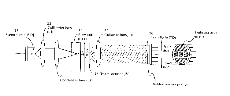
Figs. 2 and 3 illustrate the construction of a cytoanalyzer in
accordance with one embodiment of the present invention as viewed
from the top and the side, respectively. As shown, components of
the cytoanalyzer are arranged in a line on an optical axis.
Referring to Figs. 2 and 3, the cytoanalyzer includes a laser
diode (LD) 21, a collimator lens (L1 ) 22, a condenser lens (L2) 23, a
flow cell (CELL) 24, a beam stopper (BS) 27, a collector lens (L3) 25
1~ and a photodiode (PD) 26.
The laser diode 21 comprises, for exampie, LASER DIODE
TOLD9421 (maximum light output: S mW, outpu~ wavelength: 6~0 nm)
available from Toshiba Corporation. In contrast with a typical argon
ion laser having dimensions of about 15 x 1~ x 40 (cm), this laser
.0 diode has a diameter of about 10 mm, thereby contributing to a
reduction in the size of the cytoanalyzer.
The collimator lens Z2 and condenser lens 23 cooperatively
focus a laser beam emitted from the laser diode 21 onto a portion of
the flow cell 24 through which cells pass. A fine stream of blood
~5 pretreated with a reagent is allowed to flow through the flow cell
24. The direction of the flow is from the back side to the front side
of the drawing of Fig. 2, or from the upper side to the lower side of
21S~403
the drawing or Fig. 3.
On the downstream of the flow cell 24 in the optical system or
on a side opposite to the laser diode 21 are disposed the beam
stopper 27, the collector lens ~5 a";~"yed adjacent thereto, and the
photodiode 26 serving as a light-detecting device arranged a little
away therefrom. The beam stopper 27 is a vertically elongated
plate for blocking the laser beam passing through the central portion
of the flow cell 24. The collector lens 25 serves to condense light
rays scattered forward by the cells passing through the flow cell 24
and direct the light rays parallel to the optical axis.
The photodiode 26 serves as a photoelectric convertor device
for detecting the forward scatter light and converting the intensity
of the light into an electrical pulse signal. The use of the
photodiode 26 as the detecior which is compact and inexpensive is
i5 the most preferable, but other detectors may be employed.
The photodiode 26 which is adapted to detect the forward
scatter light directed parallel to the optical axis by the collector
lens 25 has a plurality of separate light-detecting surfaces capable
of detecting two types of forward scatter light rays.
Figs. 4 and 5 illustrate exemplary configurations of light-
detecting surfaces of the photodiode 26.
A first exemplary photodiode shown in Fig. 4 has five separate
light-detecting surfaces, i.e., a circular light-detecting surface C
disposed in the center thereof, light~etecting surfaces B and D
2~ shaped as shown in Fig. 4 and disposed in a horizontally symmetrical
relation with respect to the light-detecting surrace C, and light-
detecting surraces A and E shaped as shown in Fig. 4 and disposed in
- ~Is~4Sa3
a vertically symmetrical relation with respect to the light-
detecting surface C.
A second exemplary photodiode shown in Fig. S has a circular
light-detecting surface C disposed in the center thereof, and a
5 semicircular light-detecting surface A disposed on the upper side of
the light-detecting surface C.
As described above, the present invention utilizes two types
of forward scatter light rays for cytoanalysis. In this embodiment,
the photodiode 26 is adapted to detect low-angle forward scatter
10 light rays which are scattered forward at angles between 1 and 5
with respect to the optical axis and high-angle forward scatter
light rays which are scattered forward at angles between 6 and ZO
with respect to the optical axis.
The low-angle forward scatter light rays reflect the size of a
1~ cell, while the high-angle forward scatter light rays reflect the
inside structure of the cell. Therefore, the classifica~ion and
quantification of cel!s are realized by analyzing signals indicative
of these two types of scattered light rays.
In the photodiodes shown in Figs. 4 and 5, the circular light-
~0 detecting surface C located in the center thereof is adapted todetect the low-angle forward scatter light rays and the other light-
detecting surfaces are adapted to detect the high-angle forward
scatter light rays. The light-detecting surfaces B, D and E shown in
Fig. 4 are also utilized for the positional adjustment of optical
2~ system components which will be described ~ater. It is also
possible to detect the high-angle forward scatter light rays by the
combination of light-detecting surfaces A, B, D and E, or the
- 2 1 .; ~
combination of opposite surfaces A and E, or B and D. The light-
detecting surface C has, for example, a diameter of 1.5 mm. The
light-detecting surfaces A and E are each formed into a semicircular
shape having a diameter of about 6 mm, for example.
The photodiode 26 is accommodated in a metal can and has
several output terminals provided on the side opposite to the light-
detecting surfaces ror outputting electric pulse signals indicative
of the intensities of scattered light rays detected by the light-
detecting surfaces. The photodiode 26 has a diameter of about 15
mm which is about one fiftieth that of a photomultiplier tube.
The output terminals are connected to a signal processor (not
shown) utilizing a microcomputer. The signal processor essentially
consists of an ampiifier circuit, a peak detection circuit, an A/D
convertor circuit and the microcomputer. The microcomputer
includes a CPU, an ROM, an RAM, an l/O controller and a timer and is
connected to input devices such as keyboard and mouse, a display
device such as LCD or CRT and a printer, as required.
Electric pulse signals include two types of signals indicative
of the intensities of the low-angle forward scatter light and high-
angle forward scatter light and are output every time a cell passes
through a light spotted portion of the flow cell 24.
Upon receiving such electric pulse signals, the signal
processor calculates peak values, pulse widths and pulse waveform
areas of the pulse signals, then derives therefrom data necessary
for cytoanalysis, and ciassifies and counts cells.
As can be understood from the foregoing, the present invention
employs a iaser diode as the light source and a photodiode as the
- 21SS403
light-detecting device, thereby realizing a compact and inexpensive
cytoanalyzer. For example, the size of the light source portion
employing a laser diode can be reduced to less than one tenth that
employing a conventional argon ion laser.
Further, the present invention employs as the light-detecting
device a single photodiode having a pluraiity of separate light-
detecting surfaces, which are adapted to separately detect two
types of forward scatter light rays having relatively high
intensities. Therefore, the optical system components ranging from
the light source to the light-detecting device can be arranged in a
line on the optical axis. Such an arrangement reduces the size of the
cytoanalyzer.
Since the present invention does not utilize side scatter light
which is utilized in a conventional cytoanalyzer, there is no need to
provide a collector lens, pin hole, filter and light-detecting device
for the measurement of the side scatter light in the cytoanalyzer of
the present invention. Therefore, the size and cost of the
cytoanalyzer can be reduced in comparison with the conventional
cytoanalyzer. Further, the cytoanalyzer of the present invention has
a reduced number of optical system components, so that the
adjustment of the optical axis and other maintenance operations can
be facilitated.
The present invention does not empioy a light blocking device
having slits to define two different angle ranges for the detection
of two types of forward scatter light rays. Instead, the scatter
angle ranges are defined by the shapes of separate light-detecting
surfaces provided in the photodiode. This eliminates troublesome
- -
215S~03
adjustment such as the positioning of the light blocking device,
thereby facilitating the maintenance of the cytoanalyzer.
Next, there will be described an exemplary method for
classifying leukocytes with use of the cytoanalyzer of the present
5 invention.
A blood sample treated with a reagent is allowed to flow
through the flow cell 24, and cells in a fine stream of the blood
sample flowing through the-f~wv cell 24 are subjected to a laser
beam emitted from the laser diode 21.
An exemplary reagent to be preferably used for the analysis of
leukocytes has the following composition:
lonic surfactant 100- 500 mg/l
Magnesium 8-anilino-1-naphthalenesulfonate 2 9/
(organic compound)
BC30TX 1 9/l
(nonionic surfactant available from Nikko Chemicals Co., Ltd.)
HEPES 10 mM
Methyl alcohol 1 00 ml/l
PH is adjusted to 7.0 by adding an appropriate amount of NaOH.
Herein used as the ionic surfactant is
decyitrimethylammonium bromide (DTAB) in an amount of 750 ml/l,
lauryltrimethylammonium chloride in an amount of 500 mg/l,
myristyltrimethylammonium bromide in an amount of 500 mg/l, or
cetyltrimethylammonium chloride in an amount of 100 mg/l.
2~ Low-angle forward scatter light and high-angle forward
scatter light are measured after passing 30 seconds after a mixture
of 30 ~l of a blood sample and 1 ml of the aforesaid reagent is
16
- 21~540~
applied to the flow cell 24. Since only the low-angle forward
scatter light and high-angle forward scatter light are detected for
the cytoanalysis, there is no need to stain leukocytes with a
conventionally utilized reagent for the detection of fluorescence.
More specifically, a laser beam is scattered by the leukocytes
flowing through the flow cell 2A, and two types of forward scatter
light rays are detected by the photodiode 26.
The intensities of the scattered light rays thus detected are
output to the signal processor, which in tum calculates peak values,
pulse waveform areas and the like of pulse signals indicative of the
light intensities.
Based on the values thus calculated, a scattergram is prepared
as represented by the !ow-angle forward scatter intensity and the
high-angle forward scatter intensity. Since the relationship
between the low-angle forward scatter intensity and the high-angle
forward scatter light inlensity varies depending on the leukocyte
subclasses (or plots of the low-angle forward scatter light
intensity vs. the high-angle forward scatter light intensity appear
in different regions on the scattergram depending on the leukocyte
~0 subclasses), leukocytes can be classified on the basis of the
scattergram. Figs. 6 and 7 are examples of scattergrams obtained
when leukocytes are classified by using the aforesaid reagent in the
cytoanalyzer of the present invention. Fig. 6 is a schematic
scattergram, and Fig. 7 is a scattergram prepared on the basis of
?~ raw data.
The high-angle forward scatter light intensity and the low-
angle forward scatter light intGnsity are plotted as the abscissa and
21~S4~3
the ordinate, respectively.
As shown, leukocytes are classified into four subclasses, i.e,
Iymphocyte (L), monocyte (M), granulocyte (G) other than acidocyte
and acidocyte (E).
Thus, the leukoc)/tes can be classified into these four
subclasses at a time by using the cytoanaly7er and the aforesaid
reagent according to the present invention without the need for
staining the leukocytes.
It is otherwise possible to classify the leukocytes into five
subclasses by analy2ing the same blood sample treated with another
reagent which allows for the identification of basophil and
examining these analysis results along with tne aforesaid analysis
results.
To be described next is 2 method of adjusting the optical
system components of the cytoanalyzer in accordance with the
present invention.
The adjustmen~ or the optical system components is achieved
by employing the photodiode having the configuration shown in Fig.
4. The optical axis and the position of the beam stopper are each
.0 adjusted by measuring output differences among light intensities
detected by the five separate light-detecting surfaces of the
photodiode.
Fig. 8 illustrates an exemplary method of adjusting the optical
axis.
.~ Fig. 8(a) is a schematic diagram illustrating the five separate
light-detecting surfaces A to E of the photodiode 26 shown in Fig. 4.
Before starting the adjustment of the optical axis, the beam
18
21~i4()3
stopper 27 shown in Fig. 2 is removed.
Fig. 8(b) shows a laser-beam projection when the optical axis
is correctly adjusted. With the beam stopper 27 being removed, the
laser beam is projected in an elliptical shape on the light-detecting
5 surfaces on the photodiode. At this time, the laser intensities on
the light-detecting surfaces B and D arranged in a horizontally
symmetrical reiation in the photodiode are equal to each other, and
~ikewise the lase~ ff~tensities on the light-detecting surface A and E
arranged in a vertically symmetrical relation are equal to each
10 other. The intensity of the laser beam detected by the central light-
detecting surface C assumes the maximum value (Cm). If the optical
axis is offset, the offset direction can be determined by measuring
differences between the laser intensities on the light-detecting
surfaces A and E and between those on the light-detecting surfaces
15 B and D.
Figs. 8(c) to 8(f) each show a laser-beam projection when the
optical axis is offset.
Where the optical axis is upwardly offset as shown in Fig.
8(c), for example, the laser intensities on the light-detecting
20 surraces B and D are equal to each other, while the laser intensity
on the light-detecting surface A is greater than that on the light-
detecting surface E.
When the optical axis is to be manually adjusted, the signal
processor (not shown) connected to the photodiode is ailowed to
2~ measure the laser intensities and calculates values of the laser
intensities on the respective light-detecting surfaces, an output
di*erence between the laser intensities on the light-detecting
19
21~i iO~
surfaces A and E and an output difFerence between the laser
intensities on the light-detecting surfaces B and D. Then, the signal
processor causes the display device to display the calculation
results or schematic graphics representing the offset state of the
5 laser-beam projection as shown in Fig. 8(b) to 8(f).
While watching the display, an operator manually adjusts the
position of each optical system component such as lens, for
example, to downwardly move the optical axis into the state shown
in Fig. 8(b).
Thus, the operator can carry oul the manual adjustment of the
optical axis while checking the current adjustment state displayed
on the display device on a real-time basis. As seen, the optical
adjustment is achieved more easily than that carried out through
visual observation.
Since a more objective factor of the light intensity difference
is employed as a criterion, more accurate adjustment of the optical
axis can be reali~ed. The completion of successful adjustment may
preferably be notified by a sound or display color.
Where the optical axis is downwardly offset as shown in Fig.
8(d), the output difference (A - E) between the laser intensities on
the light-detecting surfaces A and E is a negative value.
Where tne optical axis is offset to the left as shown iri Fig.
8(e), the output difference (B - D) between the laser intensities on
the light-detecting surfaces B and D is a positive vaiue.
Where the optical axis is offset to the right as shown in Fig.
8(f), the output difference (B - D) is a negative value.
In these cases, the adjustment of the optical axis is carried
- 21S~403
out in substan~ially the same manner as described above.
Fig. 9 illustrates an exemplary method of adjusting the
position of the beam stopper.
Since the beam stopper 27 is a vertically elongated plate, a
5 central portion of a laser beam is blocked by the beam stopper 27,
and the photodiode 26 detects two separate side portions of the
laser beam projected thereon as shown in Fig. 9.
Where the beam stopper 27 is correctly located in a central
position as shown in Fig. 9(a), the laser intensity output differences
10 are A - E = 0 and B - D = 0, and the output of the light intensity on
the central portion assumes the minimum value (Cmin).
Where the be--m stopper 27 is offset to the left from the
central position as shown in Fig. 9(b), the laser intensity output
differences are A - E = 0 and B - D < 0.
Where the beam stopper 27 is offset to the right from the
central position as shown in Fig. 9(c), the laser intensity output
differences are A - E = 0 and B - D > 0.
Therefore, the position of the beam stopper 27 is adjusted so
that the output difference (B - D) between the laser intensities on
20 the light-detecting surfaces B and D may assume zero. By observing
the display on the display device ror checking the current
adjustment state, the manual adjustment or the beam stopper 27
can be easily ca~ied out in substantially the same manner as the
aforesaid adjustment of the optical axis. Since a more objective
~5 factor of the laser intensity is employed as a criterion for the
positional adjustment of the beam stopper 27, like the adjustment
of the optical axis, the position of the beam stopper 27 can be more
-- 21~403
accurately adjusted.
The intensity of scattered light detected by the photodiode is
output as an electrical signal. Therefore, when the cytoanalyzer of
the present invention further inc!udes a mecnanism for adjusting
the positions of the optical system components and beam stopper
and an electric driving device for actuating the position adjusting
mechanism, automaiic positional adjustment of the optical axis and
the beam stopper can be reali7ed.
More specifically, the optical axis and the beam stopper are
automatically adjusted through a reedback control by controlling the
driving device so that the laser intensity di~ference between
appropriate light-detecting surfaces measured by the signal
processor assumes zero.
As has been described, the present invenbon employs a
semiconductor lignt emitting means for emitting a laser beam and a
semiconductor light-detecting means having at least two
photosensing portions for dete~ting two types of forward scatter
light rays, thereby realizing a compact and inexpensive
cytoanalyzer.
The present invention utilizes pulse signals indicative of two
types of forward scatter light rays scattered by leukocytes in a fine
stream for the analysis of the leukocytes. Therefore, a compact and
inexpensive cytoanalyzer can be realized.
Since the cytoanalyzer of the present invention is adapted to
~5 measure output differences between ~ight intensities detected by
three types of photosensing portions of the semiconductor light-
detecting means and display the measurement results in a
22
215~3
predeiermined manner, the oplical axis and the position of a beam
stopper can be readily and accurately adjusted.