Note : Les descriptions sont présentées dans la langue officielle dans laquelle elles ont été soumises.
WO 94/21350 _ PCT/US94/02793
-I-
COMPRESSIBLE DIFFERENTIAL PP;ESSURE ENERGIZED
SEALS FOR FILTER ELEMENT'S AND THE LIKE
TECHNICAL FIELD
This invention relates generally to seals for' filter elements and the like.
More
particularly, in a filtration environment, this invention relates to a seal
interposed and
coacting between at least one end of a filter element and a housing.
Specifically, the
present invention relates to a generally resilient, compressible differential
pressure
energized seal operatively attached to at least one end of a filter element
which comprises
a compressible portion extending from an annular flange.
BACKGROUND OF THE In~VENTION
Filter elements are generally well known in the art and commonly used for
filtering liquids and gases. There are several different types of filter
elements currently
available in the market, each advantageous in one respect or another,
depending on the
type of filtration for which it is to be used. For example, one well known
type of filter
element includes hollow, generally tubular, self supposing resin impregnated
and bonded
fiber structures. Preferred embodiments of such filters are described in
Anderson U.S.
Pat. Nos. 2,539,767 and 2,539,768 and are produced. and sold by the Assignee
herein
under the trademark MICRO-KLEAN (Cuno, Incorporated, Meriden, Connecticut)
wherein the bonding system is a thermosetting resin. Broadly, these filter
elements are
relatively rigid, self supporting, thick-walled, tubular members composed
entirely of a
resin impregnated and bonded fibrous material.
Another type of filter element is also a~ hollow, tubular, self supporting
structure as mentioned above but an all thermoplastic polymeric bonded fiber
structure.
Preferred embodiments of such filters are described in Nakajima et al. U.S.
Patent
Numbers 4,100,009 and 4,197,156, and are produced and sold by the Assignee
herein
under the Trademark Betapure.
Another type of filter element is a pleated or convoluted type filter element.
Embodiments of these filters are more fully described i.n Landree U.S. Pat.
No. 3.720,323
and Brownell U.S. Pat. No. 4.464,263. These filter elements may also be self
supporting, although they can also be used with suppoirting members. The
disclosure will
_~I~~41~
WO 94121350 PCT/US94/02793
-2-
be specifically directed toward the resin impregnated and bonded fiber type
filter
elements. However, it will be understood that any type filter element may be
substituted
therefor. In any event, whatever type of filter element is employed, it is
generally used
for filtering liquids and gases by flowing radially inwardly under a
differential pressure.
Typically, these filter elements have been adapted to be sealingly clamped in
a filter housing. In the past, a sealing surface of the'~filter housing was
required to
engage the end of the filter cartridge element in order to provide a seal and
to prevent
by-pass of the contaminants being filtered from the fluid. Typically, the
sealing surface
was a circular sealing lip or knife edge protruding from the housing which
engaged the
end of the filter element and was concentric with the axis of the filter. A
sealing surface
engaged each end of the filter cartridge element. The sealing surface was
embedded into
the end of the fibrous structure to provide a seal between the edge and the
filter element.
A compression spring means or clamping means was then used to provide
sufficient force
to embed the sealing surface of the housing into the end of the filter
cartridge element.
1 S Alternately, there are filter housing and cartridge designs, which do not
use
either a sealing edge or an independent spring or clamping means to provide
for the seal
between the filter housing and cartridge. These designs feature filter
cartridges which
have a spring and seal integrally built into the cartridge construction and
seal against flat,
smooth surfaces in the filter housing. Upon installation, the filter cartridge
is compressed
between the cover and base of the filter housing and the integral spring
combined with
the filter media provides the initial sealing force at the end seals of the
filter cartridge.
However, differential pressure acts directly against this cartridge sealing
force which
effectively reduces the sealing force and eventually allows bypass to occur.
Examples
of this type of filter cartridge construction are the Peco Filter-TexTM
cartridge and the
Pall Profile PRS series filters.
Attempts have been made to solve this problem, some more successfully than
others. For example, the Assignee of the present invention has developed a
gasket
having a melt surface which abuts the filter element. The opposite surface
coacts with
the sealing surfaces of the housing to provide the necessary seal. Such a
gasket and
method for its manufacture are the subjects of U.S. Pat. Nos. x,015,316 and
5.028,327
to Ostreicher et al.
Another problem associated with these types of filter cartridge elements is
that it is often difficult to seal effectively. Various means are known for
sealing the ends
2 .~ ~ ~' 4 .~ ~~
WO 94/21350 ' PCT/US94/02793
-3-
of filter, but most, if not all, of these °neans cannot be readily used
with the preferred
type of filter element described herein and/or are expensive and inefficient
in use. For
instance, Cox et al. U.S. Pat. No. 2,726,184 describes a method for improving
the end
seals of a pleated or convoluted type filter element. The method includes
depositing an
S amount of unpolymerized, thermosetting adhesive in liquid form on the
surface of end
discs, allowing the deposited adhesive to harden, and then press fitting the
end discs onto
the end of the filter element. The adhesive may be in the form of a precut
solid adhesive
ring which may be placed in the disc. This method. is complicated and
expensive and
requires preformed end discs to be sealed to the end. of the filter element.
Another example is Kasten et al. U.S. P.at. No. 2,771,156, which describes
a pleated filter element and resilient plastic end cabs, the pleated filter
element being
embedded therein. In a process of molding the end c:ap, the ends of the
pleated element
are immersed in a mold filled with a plastic composition and cured. When the
filter
element is removed from the mold, the ends of th~~ pleats are covered with a
tough
rubber-like product, i.e., "plastisol" - a vinyl resin with fillers, pigments,
plasticizers
and/or stabilizers.
In addition, Gershenson et al. Pat. No. 5,1)75,004 discloses a filter
apparatus
having a filter bag with a sealing gasket made out of a thermoplastic
elastomeric
material. The gasket is formed such that, as the cover plate of the apparatus
is closed,
the top lip portion of the gasket deflects to form a seal against the cover
plate. Notably,
however, such a seal is sewn onto a filter bag and not attached to a filter
element.
Moreover, it is clear that the inwardly directed top portion would not have
the desired
sealing effect on the conventional filter elements de:~cribed hereinabove,
which require
the fluid to flow radially inwardly.
Notwithstanding these sealing methods, it is clear that the art has not
provided
a facile means or device by which to seal the filter element to the housing
without the
need for some sort of spring or clamping means andlor the sealing surface.
Clearly, in
Kasten et al. as well as Ostreicher et al., some sort of clamping device is
employed to
keep the sealing surface of the housing in contact vvith the various gasket-
like means
disposed at the ends of the filter element.
Accordingly, there is a well defined industrial need for a seal which will
eliminate the need for the housing to have a sealing surface and which will
adequately
WO 94/21350 PCT/US94/02793
~~.~~ 414 _ 4 _
replace the conventional spring and clamping assemblies employed with most
filtration
apparatus.
SUMMARY OF INVENTION
It is therefore, an object of the present iriwention to provide an improved
seal
for filter elements and the like.
It is another object of the present invention to provide a seal, as above,
which
is attached to at least one or both ends of a filter element and coacts with a
housing.
It is yet another object of the present invention to provide a seal, as above,
which operatively engages the housing and eliminates the need for a sealing
surface on
the housing.
It is still another object of the present invention to provide a seal, as
above,
which generally replaces conventional means of clamping or sealing the filter
element
to the housing.
It is still a further object of the present invention to provide a filter
element
having an improved seal disposed on at least one end thereof.
At least one or more of the foregoing objects, together with the advantages
thereof over the known art relating to filter elements and seals therefor,
which shall
become apparent from the specification which follows, are accomplished by the
invention
as hereinafter described and claimed.
In general the present invention provides a compressible differential pressure
energized seal coacting between a filter element and the like and a housing,
the seal
comprising a compressible portion having a large open end and a small open
end, the
large end directed toward and contacting the housing and the small end
directed toward
the filter element; and an annular flange integrally attached to the
compressible portion
at its small end and extending outwardly, the flange operatively communicating
with the
filter element.
The present invention also includes, in combination with a filter element or
the like having an inner circumferential area defining a hollow core, an outer
surface
area, and opposed ends, a compressible differential pressure energized seal
operatively
disposed upon at least one of the ends of the filter element comprising a
compressible
portion having a large open end and a small open end; and an annular flange
integrally
attached to the compressible portion at its small end and extending radially
outwardly,
~~~~4~4
WO 94/21350 ' PCT/US94/02793
the flange operatively communicating with the end of the filter element upon
which the
seal is disposed.
r
BRIEF DESCRIPTION OF THIE DRAWINGS
Fig. 1 is a side elevational view, partially in longitudinal section, of a
filter
element having a sealing article of the present inventicm operatively disposed
on each end
of the filter element;
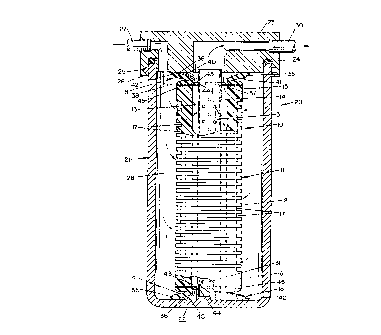
Fig. 2 is a longitudinal sectional view of a filtration apparatus having the
filter element of Fig. 1 operatively positioned therein;
Fig. 3 is an enlarged top plan view of thE: filter element of Fig. 1;
Fig. 4 is a sectional view of taken substantially along line 4-4 in Fig. 3;
Fig. 5 is a side elevational view partially in section of an alternative
embodiment of the sealing article of the present invention as disposed upon
one end of
the filter element;
Fig. 6 is a side elevational view partially in section of another embodiment
of the sealing article;
Fig. 7 is a side elevational view partially in section of yet another
embodiment of the sealing article of the present invention; and
Fig. 8 is a side elevational view partially in section of still another
embodiment of the sealing article of the present invention.
CA 02155414 1999-10-27
WO 94121350 PCTIUS94I02793
-6-
PREFERRED EMBODIMENT FOR CARRYING OUT THE INVENTION
As discussed hereinabove. apart from the novelty of the filter elements as
taught by the present invention, filter elements used in this invention are
generally well
known in the art. As previously indicated, these elements may be produced, for
example,
as described in Assignee's U.S. Pat. Nos. 2,539,767 and 2.539,768 to Anderson.
In
the current MICRO-KLEAN production process, the Anderson process has been
modified so that the fibers are vacuum accreted from a uniform aqueous
dispersion
and then, subsequently, vacuum impregnated with a water soluble thermosetting
resin.
Accordingly, the filter elements to which the present invention pertain
preferably
generally comprise a relatively rigid, self supporting, porous, thick-walled
tubular
member composed entirely of resin-impregnated and bonded fibrous materials.
However, it will be appreciated that, inasmuch as the present invention
relates
to an improved means for sealing the filter element to the housing, any type
filter
1 S element may be substituted for the preferred filter elements without
departing from the
scope or spirit of the invention. For convenience, the resin impregnated and
bonded fiber
type filter elements are illustrated and exemplified herein. However, it will
be
understood that other conventional filter elements may be used and that the
present
invention is not necessarily limited thereto.
With reference to the drawings, the filter element of the present invention is
depicted in Fig. 1 and is indicated generally by the numeral 10. The filter
element 10
preferably comprises a cylindrical structure or body 11 having an outer
surface 12, inner
circumferential surface 13 defining a hollow axial core 14, and opposed ends 1
S and 16.
The outer surface 12 may include grooves 17 to provide increased surface area
and
contaminant capacity. At each end 15 and 16 of the element 10 is a generally
resilient,
compressible differential pressure energized seal generally indicated by the
numeral 18
and used to seal the element 10 within a housing as more particularly
discussed
hereinbelow.
The filter element 10 is typically part of a filtration apparatus indicated
generally by the numeral 20 in Fig. 2. As shown, the apparatus 20 generally
includes
a housing, generally indicated by the numeral 21, and the element 10
operatively
positioned within the housing 21. The housing 21 typically includes a
container-like base
22 and a cover 23 securably attached to the base 22 by any means known in the
art such
WO 94/21350 ~ PCT/US94/02793
_7_
as by complementary lips 25 and 26 on base 22 and cover 23, respectively with
an O-
ring 24 therebetween. An inlet port 27 is shown in filtration apparatus 20,
and more
particularly, in cover 23 for providing an inlet for thE: fluid to be filtered
into a chamber
28 defined between the housing 21 and the element 10. Similarly, a second port
30 is
shown as communicating between the hollow axial core 14 and the external
environment
through the cover 23 in order to provide the fluid which has been filtered
with an outlet.
Accordingly, it should be clear that filter element 10 is intended to be used
for filtering
liquids and gases which are usually caused to flow radially inwardly under a
differential
pressure (see Fig. 2).
With further reference to Fig. 2, the housing 21 typically also includes a
foraminous, hollow centering rod 31 securably attached to the bottom of the
base 22.
Rod 31 is generally positioned radially concentricall3~ within base 22 such
that the filter
element 10 can be placed thereover, the hollow axial ~~ore 14 of the element
10 receiving
the rod 31.
In use, it will be appreciated that fluids such as liquids and gases usually
enter the filtration apparatus 20 through port 27 and are received in chamber
28. The
fluid then passes through the wall of the filter element 10 or cartridge and
is collected
in the axial core 14 of the element 10. The filtered fluid may then pass
through the
outlet port 30 to the point of use.
Typically, the compressible differential pressure energized seal 18 of the
present invention should be capable of withstanding the operating pressures
and
temperatures required of the filter element 10 in its intended use and thus,
no particular
operating range has been specified herein.
The filter element 10 may be used in varying lengths or multiples of a single
length, stacked one on top of another. In such an arrangement, all of the
elements in
multiple height stack arrangements are preferably fastened together by a
bonding agent,
e.g., polypropylene, to assure alignment and permanent bonding for positive
sealing
against by-pass of fluids.
The basic novel component of the filtration apparatus 20, and more
specifically, the filter element 10 of the present invention is the generally
resilient,
compressible differential pressure energized seal 18 positioned at the ends 1
S and 16 of
the filter element 10. The seal 18 is preferably made from a thermoset rubber
or a
thermoplastic elastomer, depending on the operating conditions, e.g.,
temperature, type
WO 94/2135 ~ ~ ~ ~ ~ - 8 - PCT/US94/02793
of fluid, etc., of the apparatus 20. An example of thermoset rubbers suitable
for use in
making the seal 18 are ethylene-propylene terpolymers ~(EPDM). An example of a
thermoplastic elastomer suitable for the present invention is Santoprene, a
polymer alloy
of polyproplyene and EPDM available from and. a'~trademark of Monsanto
Company.
The seal 18 generally comprises a compressible portion 35 generally having ,
a large open end 36 and a small open end 37 and an annular flange 38
integrally attached
to the compressible portion 35 at the small end 37 thereof. As shown in Figs.
1 and 4,
the compressible portion 35 of the seal 18 is preferably generally frusto-
conical in shape
and includes a generally smooth radially inwardly slanted inner surface 40 and
an outer
surface 41 which is similarly slanted proximate to its small end37 but which
is tapered
so as to present a beveled surface 42 near its large end such that beveled
surface 42
communicates between the inner surface 40 and the outer surface 41 of seal 18.
As
depicted in Fig. 1, the annular flange 38 extends generally radially outwardly
and
operatively communicates with one or both ends 15, 16 of the filter element
10.
Furthermore, as more particularly shown in Fig. 3, the seal 18 may also
comprise at least one, and preferably three flaps 43 integrally formed with
and extending
inwardly from the interface between the compressible portion 35 and the flange
38. The
flaps 43 generally lie parallel to the flange 38. Functionally, the flaps 43
are used to
align the filter element 10 on the centering rod 31 when the element 10 is
placed
thereover. For example, as shown in Fig. 3, the edges 44 of the flaps 43
tangentially
contact the centering rod 31. Based upon this contact, the filter element 10
can be
properly positioned over rod 31 in housing 21.
In the drawings, centering rod 31 is shown as generally cylindrical. However,
triangular rods are also common and therefore, it will be appreciated that the
seal 18 with
flaps 43 can accommodate such a triangular rod and center the filter element
placed in
a housing containing such a rod. Moreover, the invention should not
necessarily be
limited to three flaps positioned as shown in the drawings. Accordingly, a
rectangular
or other conventional rod may also be used with the present invention, the
number and
position of the flaps 43 being adjusted for use therewith.
There are various means by which the compressible differential pressure
energized seal 18 can be operatively attached to the filter element 10. More
particularly,
depending upon the compatibility between the seal 18 and filter element 10, as
well as
the intended use of the filter, the seal may be affixed, or operatively
associated with the
WO 94/21350 PCT/US94/02793
-9-
latter in at least three different manners, i.e., mechanically attached;
affixed with an
appropriate adhesive; or, thermally bonded thereto. If the compressible
differential
pressure energized seal 18 is a thermoset rubber mal:erial, it can be
operatively attached
to the filter element 10 by adhesive means or mechanical means. Adhesive means
shall
S include any means known in the art. In addition to those attachment methods
mentioned
previously, a thermoplastic elastomer material can be; bonded to the filter
element 10 by
any means known in the art and preferably, by thermal bonding. Sometimes an
intermediate compatible thermoplastic disc 45 which is bondable to the filter
element 10
is required for the thermal bonding. Figs. 1 and 4 generally show the
preferred
I 0 embodiment of the seal 18. The preferred embodiment using a Santoprene
elastomer seal
with a phenolic resin bonded Micro Klean filter element requires the use of an
intermediate polypropylene disc which can be thermally bonded to the filter
element
either before or after being operatively attached to the seal. The disc can be
thermally
bonded or mechanically affixed to the seal.
15 Now, referring to Figs. S-8, the seal 18 may further include a skirt 46
which
is integrally connected to the flange 38 and which extends further within the
housing 21
so as to operatively engage the filter element 10. As can be seen in the
various
embodiments shown in Figs. 5-8, the skirt 46 can extend from any of several
junctures
on flange 38.
20 Specifically, for the embodiment depicted in Fig. 5, the skirt 46 extends
from
the outer periphery of the flange 38 tightly around one end of the filter
element 10. The
skirt 46 preferably includes at least one inwardly directed flange 47 at the
distal end 48
of the skirt 46 which is received by at least one of t'he grooves 17 in the
filter element
10. Accordingly, the seal 18 is attached to the element 10 by the skirt 46
sealingly
25 engaging the element 10, instead of via an adhesive.
In Fig. 6, another embodiment of the seal 18 is depicted wherein the filter
element 10 includes an annular recess SO in the end; 15 or 16 thereof. The
recess 50
receives the skirt 46 which, in this embodiment, extends generally from the
mid-region
of the flange 38. At least one annular barb 51 may ring skirt 46, preferably
on the outer
30 surface 52 thereof so as to prevent the seal from disengaging the recess
50. In operation,
the barbs 51 are slidably received within recess 50 as part of skirt 46.
However. because
of their angle and cut, the barbs 51 provide a rather through seal and are not
easily
disengaged from recess 50.
WO 94/21350 2, PCT/US94/02793
- - 10-
With reference to Fig. 7, yet another embodiment of the seal 18 is shown
wherein the skirt 46 extends from the interface 53 of the compressible portion
35 and the
flange 3 8. Here, the skirt 46 generally engages a counterbore 54 in the inner
f
circumferential surface 13 of the filter element l ~: ~ While the skirt 46 may
also include
at least one barb 51 as detailed hereinabove, it will be appreciated that in
order to secure ,
the seal 18 to the filter element 10, an independent means for retaining the
seal 18 to the
element 10, such as compressible band 55, can be employed. Where band 55 is
used,
it is preferably positioned so as to forcefully contact the inside surface 56
of skirt 46
under flaps 43 upon expansion. A lip 57 may extend inwardly from the distal
end 58
of skirt 46 and act in conjunction with flaps 43 to sealingly position the
band 55
therebetween. Accordingly, the seal 18 is secured to the filter element 10 at
skirt 46
which is secured between the retaining band 55 and the inner circumferential
surface 13
of the filter element 10.
. With reference to Fig. 8, the skirt 46 again extends from the outer
periphery
of the flange 38 and fits tightly around the filter element 10, similar to
Fig. 5. However,
in Fig. 8, the skirt 46 is secured to the filter element 10 at its outer
surface 12 by a
different retaining band 60 from that in Fig. 7. The band 60 forcefully
engages the skirt
46 around the filter element 10 such that the skirt 46 is clamped between
retaining band
60 and the outer surface 12 of the filter element 10.
Returning to Fig. 2, it will be appreciated that the compressible portion 35
of the seal 18 provides a necessary seal so as to eliminate the need for any
additional
clamping or sealing means as conventionally known in the art. Notably, the
compressible
portion 35 having its large end 36 directed toward and contacting the housing
21 and its
small end 37 directed toward the filter element 10 is capable of sealing
against a flat
surface, as presented by base 22 and cover 23 in Fig. 2. The sealing surface
is not
required to align itself with the upper rim of the seal 18 as defined by the
large open end
36. In fact, the seal 18 can readily compensate for generally non-aligned
angles or
surface which are not "square" with the large open end 36. Moreover, the seal
18 is
capable of sealing under minimal or maximum deformation. Thus, while the seal
18 is
preferably capable of compressing or deforming about one-half inch, it does
not have to
compress fully in order to create a suffice seal.
r
Importantly, the stiffness and compression force characteristics of the seal
18
are generally controlled by the hardness or durometer of the material, the
thickness of
2~~~4I
WO 94/21350 - PCT/US94/02793
- 11 -
the compressible portion 35, and the angle at which the compressible portion
35 is
slanted. Moreover, while it is the deformation of the compressible portion 35
which
provides the necessary initial sealing force, the seal 18 is also differential
pressure
energized. That is, once the seal 18 is seated against the cover 23 as shown
in Fig. 2,
the differential pressure that develops across the filter element will
increase the sealing
load thus, maintaining an adequate seal. More importantly, as the differential
pressure
increases, in the filtration apparatus 20, the seal 18 'becomes more securely
engaged to
and sealed against the cover 23.
In operation, the filter element 10 can be; placed in housing 21 by sliding it
over centering rod 31. Notably, filter element 10 may employ the seal 18 at
only one
end. However, when this is the case, it is highly recommended that the other
end of the
element have some other suitable means for sealing in order to promote the
operation of
the device. As shown in Fig. 2, seals 18 are on both ends of the element 10
and when
cover 23 is secured onto base 22, both seals 18 can compress and sealingly
engage the
element 10 within housing 21. As can be seen in Fig. 2, the seals 18 generally
compress
by folding or deforming at the interface of the compressible portion 35 and
the flange
38. Accordingly, the large end 36 of the compressible portion 35 is forced
closer to the
small end 37 and increases in diameter. This creates the required seal.
Thus it should be evident that the device quid method of the present invention
are highly effective in sealing the filter element 10 within the housing 21.
The invention
is particularly suited for use in filtration apparatus, but is not necessarily
limited thereto.
The device and method of the present invention c;an be used separately with
other
equipment and the like for sealing parts together.
Furthermore, it will be appreciated that a falter element 10 which employs the
seal 18 is generally self centering on the centering rod 31 due to the flaps
43 of seal 18.
It will also be appreciated that no springs or clamps are required to hold the
seal in place
between the housing 21 and the element 10.
Based upon the foregoing disclosure, it sl'nould now be apparent that the use
of the apparatus and/or seal described herein will carry out the objects set
forth
hereinabove. It is, therefore, to be understood that atiy variations evident
fall within the
scope of the claimed invention and thus, the selection of specific components
for the
apparatus 20 and filter element 10 can be determine~3 without departing from
the spirit
of the invention herein disclosed and described. In 'particular, as previously
stated, the
WO 94/21350 PCT/US94/02793
-12-
filter element depicted for the present invention is not necessarily limited
to resin
impregnated and bonded fiber type filter elements. Moreover, other means for
retaining
the seal 18 on element 10 can be substituted for the bands disclosed in Figs.
7 and 8 or
for the skirt 46 as noted hereinabove. Thus, the sco~'e c~f the invention
shall include all
modifications and variations that may fall within tlie~ scope of the attached
claims.