Note : Les descriptions sont présentées dans la langue officielle dans laquelle elles ont été soumises.
t .' 215591~ ?ress Ma
SKYLIGHT WITH MODULAR SHAFT
BACKGROUND OF THE INVENTION
The present invention relates to skylights, and more
particularly to a skylight having a modular shaft.
S Skylights have long been used to allow natural light to
enter a building through an opening formed in the roof. Skylights
-are available in variety of designs and shapes to fit almost any
residential or commercial structure.
Typically, a skylight lS installed by mounting a curb
around an opening formed in the roof. The curb mounts directly to
the roof in a weather-tight fashion to receive a glass panel
assembly. A second opening is formed in the ceiling immediately
below the opening formed in the roof, and a shaft is constructed
between the two openings to hide the joists, rafters, and other
roof members from sight. The shaft is typically constructed by
framing and sheetroc~ing sidewalls between the two openings. This
process requires skilled labor and is costly in terms of both time
and materials.
A second technique for installing a skylight includes the
use of a prefabricated shaft, such as the light well disclosed in
U.S. Patent No. 4,916,872 to Young. Young discloses a one-piece,
prefabricated shaft or light well that includes four sidewalls
extending upwardly from a flange. The light well also includes a
support ledge formed around the sidewalls to hold the shaft in
2S place as described below. To install the Young light well, an
opening is formed in the both the roof and the ceiling of the
structure. The opening in the ceiling must be formed directly
~` 215S~ll
below the opening in the roof to allow the flange to properly
engage the ceiling. Next, the upper edge of the sidewalls is cut
to match the height and pitch of the roof, and to either abut with
the skylight or its box framing. This can be done by inserting the
ahaft up through the openings, until the flange engages the
ceiling, and then marking the shaft as necessary for cutting. Once
~marked, the shaft can be removed and cut. Next, the shaft is
reinserted into the openings, and a support frame is constructed
around the shaft to engage the support ledge and maintain the l-ight
well in place. Finally, the curb and glass panel assembly are
mounted to the roof.
While eliminating the need to box frame and sheetrock,
the second technique still requires additional labor and materials
to construct the support frame. It also requires that the shaft
extend perpendicular to the ceiling rather than the roof. As a
result, the size of the opening formed in ceiling is substantially
smaller than could otherwise be obtained with a shaft extending
perpendicular to the roof. Further, the one-piece light well is
relatively bulky, thereby increasing the cost of shipping and
packaging, and also making product handling and installation more
difficult.
SUMMARY OF THE INVENTION
The aforementioned problems are overcome by the present
invention wherein a skylight is provided with a modular shaft
having interconnected panels that are secured directly to the
skylight curb.
2~ ~i9il
The present invention generally includes a glazing
material, a curb, a shaft, and a trim ring. The glazing material
mounts directly to the curb and typically includes an insulating
glass assembly. The curb in turn mounts to the roof around a
skylight opening and defines a downwardly opening channel with at
least one serrated wall to receive the shaft. The shaft extends
~downwardly from the curb and includes modular panels that are
interconnected by friction-fit corner connectors. A serrated hook
is mounted to the upper edge of each panel. The hook fits within
the channel to secure the panel directly to the curb. The lower
end of each panel is trimmed even with the ceiling, and a variable
size trim ring is attached to the ceiling to trim the skylight
opening .
The present invention provides a skylight having a
simple, yet fully functional, modular ~haft that is easily
installed and pleasing to the eye. The panels snap-fit directly to
the curb, thereby eliminating the need for additional framing to
support the skylight. Further, the panels are interconnected at
the point of installation, thereby providing for ease of packaging
and shipping. In addition, the shaft extends perpendicular to the
roof, thereby increasing the size of the skylight opening formed in
the ceiling when installed in a pitched roof.
These and other objects, advantages, and features of the
present invention will be more fully understo~d and appre~iated by
reference to the detailed description of the preferred embodiment
and the drawings.
21S~9 11 - -
BRIEF DESCRIPTION OF THE DRAWINGS
Fig. 1 is a perspective view of the present invention
installed in a conventional building structure;
Fig. 2 is an exploded perspective view of the skylight;
Fig. 3 is a sectional view of the skylight along line
III-III of Fig. 1;
- Fig. 4 is a perspective view of the hook; and
Fig. 5 is a perspective view of the trim ring.
DETAILED DESCRIPTION OF THE PREFERRED EMBODIMENT
A skylight according to a preferred embodiment of the
present invention is illustrated in Fig. 1 and generally designated
10. Fig. 1 shows the skylight 10 installed with a conventional
pitched roof 200 and having a shaft 18 extending between an opening
formed in the roof and an opening formed in the ceiling 250 below.
~hile the skylight is described in connection with a flat ceiling,
it should be readily apparent that it is equally well suited for
installation in a cathedral ceiling. For purposes of this
disclosure, directional terms, such as "upwardly", "downwardly",
"top", "bottom", "upper", and "lower" will be used to denote
directions relative to the normal orientation of an installed
skylight. In addition, the terms "inwardlyn, "outwardly", "inner",
and ~outer" will be used to denote the directions toward and away
from the center of the opening defined by the skylight curb 12.
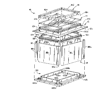
As perhaps best illustrated in Fig 2, the present
invention generally includes a curb 12, an insulating glass panel
assembly 14, a retainer 16, a modular shaft 18, and a trim ring 20.
-` 21~5911
The curb 12 is a peripheral frame manufactured by mitre cutting and
welding individual curb members from an extruded, elongated
polymeric profile. In the preferred embodiment, the curb 10 is
substantially rectangular and includes four curb members 12a-d
dimensioned to provide an assembled frame that fits around the
desired skylight opening.
- Referring now to Fig. 3, the curb 12 generally includes
spaced apart and substantially parallel inner and outer walls 30
and 32 that, when installed, extend upwardly from the plane defined
by the roof. Top 34, center 36, and bottom 38 walls extend
perpendicularly between, and cooperate with, the inner and outer
walls 30 and 32 to form a generally rectangular structural member
40 extending the length of each curb member 12a-d. A portion of
the inner surface of the inner wall 30 is serrated by a plurality
of longitudinal, closely spaced grooves 42. A first longitudinal
recess 44 is formed in the top wall 34 to seat a gasket 70 as
described below. A second longitudinal recess 50 is formed in the
outer wall 32. A pair of parallel, spaced apart ribs 46 and 48
extend outwardly along opposite longitudinal edges of recess S0.
The facing surfaces of ribs 46 and 48 are grooved to form a screw
boss extending the length of each curb member. A retainer support
lip 52 extends downwardly from the outer edge of rib 48. A
longitudinal spacing rib 64 extends downwardly from a central
portion of the bottom wall 38 to ensure proper alignment of the
curb 12 with the roof 200.
2 1 ~ 5 9 1. 1 ~ --
The curb 12 also includes an outer flange 54 extending
perpendicularly outward from the lower edge of the outer wall 32,
and an inner flange 56 extending perpendicularly inward from a
central portion of the inner wall 30. A series of mounting holes
555 are formed through the outer flange 54 to allow the curb 12 to
mount to the roof 200 by conventional fasteners, such as screws or
-roofing nails. A second longitudinal spacing rib 58 extends
downwardly from a central portion of the inner flange 56 to
facilitate proper spacing of the shaft 18 with respect to the curb
1012. A lower flange 60 extends downwardly from an inner portion of
the inner flange 56. A ridge 62 is formed longitudinally along the
outer, lower edge of the lower flange 60 to engage the installed
shaft 18. Together, the inner wall 30, inner flange 56, and lower
flange 60 cooperate to define a channel 72 for receiving the shaft
1518 as described below.
In a preferred embodiment, the curb 12 further includes
an upper flange 66 extending upwardly from a central portion of the
inner flange 56 and a screen support lip 68 extending inwardly
along the upper edge of the upper flange 56. Together, the inner
20flange 56, upper flange 66, and screen support lip 68 cooperate to
define a channel 74 for receiving a screen assembly.
As noted above, the skylight 10 further includes a glass
panel assembly 14. The glass panel assembly 14 is preferably a
conventional insulating glass having a spacer frame 80 sandwiched
25between a pair of spaced apart 1/8 inch high strength, glass panels
82a-b. The panel assembly 14 is dimensioned to fit upon the top
21~591 t
'_
wall 34 of the curb 12 where it is secured by the retainer 16 as
described below. Alternatively, the glass panel assembly 14 can be
replaced by a variety of other glazing materials, such plastic or
other transparent or translucent materials.
s As perhaps best illustrated in Fig. 3, the glass panel
assembly 14 is secured to the curb 12 by retainer 16. In a
-preferred embodiment, retainer 16 is manufactured from an extruded,
elongated, L-shaped profile of aluminum having top and side walls
76 and 78. Individual retainer members 16a-d are mitre cut and
welded to form a peripheral frame. The top wall 76 of the retainer
extends inwardly and includes a downwardly extending ridge 81 along
its inner edge to engage the glass panel assembly 14. A plurality
of mounting holes 83 (See Fig. 2) are formed through the side wall
78 of the retainer 16 in alignment with recess 50.
The shaft 18 generally includes four rectangular,
expanded polystyrene panels 18a-d each having a 0.040 inch vinyl
skin 84 laminated to a single major surface (See Figs. 2 and 3).
The width of each of the panels 18a-d is selected to match the
width of a corresponding curb member 12a-d, and the height of each
panel 18a-d is selected to exceed the typical span between the roof
and ceiling openings. A longitudinal groove 85 is formed in an
upper portion of the outer surface of each panel 18a-d to
facilitate mounting as described below. While expanded polystyrene
provides the desired insulating and structural properties, the
panels can be manufactured from a variety of other rigid, light-
weight materials, such as pressboard, fiberboard, and fiberglass.
-` 21~;)91.1
The panels 18a-d are interconnected by a number of corner
connectors 86. As perhaps best illustrated in Fig. 2, each corner
connectors 86 is an elongated, extruded polymeric profile defining
a pair of longitudinal channels 88 and 90 opening in directions
S normal to one another. Adjacent panels are friction-fit into the
channels 88 and 90 of the appropriate corner connectors 86 to
-intersecure the panels in a rectangular configuration.
A hook 92a-d is mounted to the upper edge of each panel
18a-d to allow the panel to snap-fit into channel 72 formed in the
curb 12. As perhaps best illustrated in Fig. 4, the hook 92a-d is
an elongated, extruded, generally L-shaped polymeric profile having
top and side walls 94 and 96. A portion of the outer surface of
side wall 96 is serrated by a plurality of longitudinal, closely
spaced grooves 98 adapted to engage grooves 42. A barbed spine 100
extends inwardly from a central portion of the inner face of side
wall 96 to engage groove 85, thereby securing the hook 92a-d to the
upper edge of the appropriate panel 18a-d. A pair of angled
flanges 97 and 99 extend upwardly toward each other from opposite
longitudinal edges of the top wall 94. These flanges 97 and 99
help to guide the hook 92a-d into the channel 72 and to ensure
appropriate spacing.
As noted above, the skylight 10 also includes a variable
size trim ring 20 that-functions to trim the juncture of the shaft
18 and ceiling 250. In a preferred embodiment, the trim ring 20 is
a peripheral frame manufactured from two L-shaped end members llOa-
b extending between two L-shaped side members 112a-b (See Fig. 5).
-- 8
2l 5~911
The end members llOa-b each include a bottom wall 114a-b and a
sidewall 1l6a-b. The bottom wall 114a-b is preferably manufactured
from wood and includes marginal portions 118a-b that extend beyond
opposite longitudinal ends of sidewall 116a-b. Notches 120a-b are
5formed in the marginal portions 118a-b of each bottom wall 114a-b
to receive the bottom wall 124a-b of the side members 112a-b. The
~sidewalls 112a-b of the end members are preferably manufactured
from plastic and have an L-shaped profile dimensioned to fit within
the ends of the skylight opening formed in the ceiling 250 and to
10attach to the bottom wall 114a-b as described below. Preferably,
the side members 112a-b each include a wood bottom wall 124a-b and
a plastic sidewall 126a-b. The bottom walls 124a-b are dimensioned
to extend between the end members llOa-b and to fit within notches
120a-b to provide a flush upper surface for engagement with the
15ceiling 250. The sidewalls 126a-b are similar in profile to
sidewalls 112a-b and are dimensioned to extend between the end
members llOa-b within the skylight opening formed in the ceiling.
The bottom walls of both the side and end members each include a
narrow longitudinal recess 122a-b adapted to receive the
20appropriate sidewalls. The bottom and sidewalls are preferably
interconnected by stapling the corresponding sidewall into recess
122a-b. While the trim ring 20 is preferably manufactured from
wood and plastic, a variety of other materials will suffice.
~ 21S~91l
ASSEMBLY AND INSTALLATION
The present invention can be installed in commercial or
residential structures. First, a skylight opening matching the
dimensions of the skylight 10 is cut through both the roof 200 and
ceiling 250. Typically, the openings extend between a pair of
joists and are box framed with headers to provide the necessary
-structural support. Any shingles, shakes, or roof coverings
immediately surrounding the opening are removed to allow the outer
flange of the curb 12 to lie directly upon the roof 200. The curb
12 is then mounted to roof 200 around the skylight opening by
driving screws or roofing nails into the roofing through mounting
holes 55. Once the curb 12 is installed, a gasket 70 is applied
around the top wall 34 in recess 44. The gasket is preferably a
foamable gasket such as Readiseal sold by ODL, Inc. of Zeeland,
Michigan. However, a conventional rubber gasket may be
substituted.
The glass panel assembly 14 is placed upon the top wall
34 of the curb 12 and secured by retainer 16. Typically, the glass
panel assembly 14 is purchased preassembled from any of a variety
of well known suppliers. As shown in Fig. 3, a silicone sealant
150 is applied between the retainer 16 and the glass panel assembly
14 to provide a weather-tight seal. The retainer 16 is secured
directly to the curb 12 by a plurality of screws 152 extending
through mounting holes 82 into recess 50.
Subsequently, each of the panels 18a-d are inserted up
through the skylight opening in the ceiling into channel 72. The
- 10 --
` 21~5911
panels 18a-d are inserted with the vinyl skin 84 facing inwardly.
The panels are marked along the edge of the ceiling, removed from
the opening, and cut. If necessary, the corners connectors 86a-d
are cut to match the height of the panels 18a-d. Next, the shaft
18 is assembled by interconnecting adjacent panels 18a-d with the
corner connectors 86a-d. The hooks 92a-d are mounted to the top of
-the corresponding panels 18a-d, and the entire shaft 18 is
reinserted through the skylight opening so that the hooks 92a-d
snap-fit into channel 72. The serrated surfaces of the hooks 92a-d
engage the serrated surfaces of channel 72 to resist removal of the
shaft 18 from the curb 12.
The trim ring 20 is assembled by cutting the side members
112a-b to match the length of the skylight opening formed in the
ceiling. This length may or may not match the length of the
skylight opening formed in the roof depending on the pitch of the
ceiling and roof. For example, when a 3 foot long skylight is
installed in a roof having a 12/4 pitch, the length of the ceiling
opening will be approximately 3 feet 2 inches. Once the side
members 112a-b are cut, they are inserted into the opening as shown
in Fig. 3 and secured to the ceiling by conventional fasteners,
such as screws 153. Next, the end members 114a-b are inserted into
the skylight opening such that notches 12Oa-b fit over the
longitudinal ends of the side members 112a-b. The end members
114a-b are secured to the ceiling 2s0 by conventional fasteners,
such as screws.
~1559~ 1
The present invention has been described in connection
with a fixed skylight. However, the present invention is equally
well suited for use with a ventilating skylight. When used in
connection with a ventilating skylight, a conventional screen
assembly (not shown) can be installed in channel 74 to exclude
pests and debris.
- In addition, the present invention has been described
with a rectangular configuration. One of ordinary skill in the art
will immediately recognize that the present invention can be
adapted to provide nearly any desired configuration--including but
not limited to pentagonal, heptagonal, or octagonal configurations.
The above description is that of a preferred embodiment
of the invention. Various alterations and changes can be made
without departing from the spirit and broader aspects of the
invention as set forth in the appended claims, which are to be
interpreted in accordance with the principles of patent law,
including the doctrine of equivalents.