Note : Les descriptions sont présentées dans la langue officielle dans laquelle elles ont été soumises.
2155993
TITLE OF THE INVENTION
PAPER BINDER
BACKGROUND OF THE INVENTION
1. Field of the Invention
The present invention relates to a binder which removably
binds from one to several pages, and more particularly relates to a
paper binder which conducts retention by elastically pressing down
upon the corner portion of the pages to be bound.
2. Description of the Related Art
When collecting and storing comparatively small-sized paper of
memos, slips, or the like, wide use is made of a binder called a
memo holder or memo binder where a freely pivoting pressing member
is provided on one side of a hard mount, and where the free end
side of the pressing member constantly is made to press against the
mount by means of a spring. With regard to this type of binder, as
a user successively receives or produces more memos or slips, the
user opens the free end side of the pressing member against the
spring force and places these memos or slips on top of the memos or
slips already fastened on the mount, releases the force holding
open the free end side of the pressing member, and thereby retains
the paper by the pressing member. Thus, retention is made possible
by an extremely simple operation. In the case where the bound
memos or slips are removed from the binder, the user merely has to
open the free end side of the pressing member, which is very
1
2I ~~993
convenient.
The concept for the pressing and binding of paper in such a
manner as mentioned above is not only used for small-sized paper
such as memos and slips, but is also used in binders which fasten
comparatively large materials and report paper of B5 and A4 size,
as well as large pages of copier paper, etc. That is, a pressing
means is provided so that the left side area of the paper to be
bound is pressed against the rear cover of a cover composed from a
front cover, a rear cover, and a back cover. The pressing means is
composed from a lever which is supported so that one end is freely
movable, and a pressing member which is released when the free end
of the lever is lifted, which forms a belt and is elastically
pressed to the rear cover side when the free end of the lever is
turned so as to make the lever horizontal, and which presses the
left side area of the paper to be bound.
With regard to these types of holders or binders, not only it
is extremely simple to bind and release paper as explained above,
but also since it is also unnecessary to open a hole in the paper
for purposes of having a pipe, a string, a band or the like pass
through in order to bind the paper, no injury is inflicted on the
paper.
The aforementioned holders or binders are preferable from the
standpoint of inflicting no injury on the paper, but since one side
of the paper is pressed down, it is difficult to leaf through the
2
. ~ 2155993
paper when numbers of pages are bound together. Moreover, in the
case of memos or slips, the size varies according to the user and
the dimensions of the recorded contents, and unevenness tends to
occur. In this context, when the user conducts blanket binding
without regard to size, and when the user later looks over these
memos or slips, particularly in the case where the user looks at a
small memo or slip which is fastened underneath a large memo or
slip, the user is not able to see it unless the user leafs through
the pages so that the memo or slip which is fastened on top is
strongly bent over. Yet, if the bending force becomes stronger
than the pressing force of the pressing member, it is no longer
possible to press the memos or slips, and the memos or slips fall
away from the pressing member.
Furthermore, in the case of comparatively large paper of BS or
A4 size, the elasticity of the paper also becomes larger compared
to memos or slips, and a stronger pressing force is required of the
pressing means. Yet, if a spring with a large spring elasticity is
used in order to obtain a strong pressing force, it also becomes
necessary to apply a strong force in turning the lever, and
handling becomes difficult.
Additionally, in the case where a large number of pages are
bound, the binding portion becomes larger as it goes to the rear,
the inconvenience arises that the edge of the opened portion is
covered by the binding portion and cannot be seen.
3
215599
SUMMARY OF THE INVENTION
The object of the present invention is to provide a paper
binder wherein a plurality of pages are able to be securely
retained without injury to the paper, wherein a user can view all
contents recorded on the surface of the paper when the user leafs
through the pages, wherein it is easy to leaf through to the end
even when there are a large number of pages, and wherein the pages
are not dislodged during leafing.
Another object of the present invention is to provide a paper
binder which has a simple configuration with a small number of
portions, and whose assembly is easy.
In order to attain the above objects, according to an aspect
of the present invention, a paper binder comprises: a rectangular
mount; a lever means extending in parallel with one edge of the
mount and having one end rotatably supported at a corner portion of
the mount; a spring means supported on the mount and having
opposite ends one of which is fixed to the lever means so as to
urge a free end of the lever means upward elastically; a pressing
means attached to the other one of the opposite ends of the spring
means so that the pressing means is elastically pressed in the
direction toward the mount by an elastic force of the spring means
to thereby grip a corner of paper disposed between the pressing
means and the mount when the free end of the lever means is pressed
downward against the elastic force of the spring means; and a
4
2155993
locking means for locking the lever means when the free end of the
lever means is pressed downward to maintain the lowered state of
the lever means.
In the case where paper is bound by a binder configured in
this way, first, the lever means whose free end is locked downward
by the lock means is released from the lock means. As a result,
the free end of the lever member is rotated upward by the elastic
force of the spring means, and the elastic pressure toward the
mount exerted by the pressing means is eliminated. Here, if a
corner of paper is fitted between the mount and the pressing means,
if the free end of the lever member is pressed downward, and if the
lever member is again locked by the lock means, the pressing means
elastically presses against the mount, and the corner of the paper
is firmly gripped between the pressing means and the mount.
Moreover, since the pressing means contacts the narrow portion at
the corner of the paper, even if the paper is bent from this
portion, the bounce of the paper generated by the bending is weak,
and even if a large number of pages are opened by being bent from
their corner, the overall bounce does not become large.
Accordingly, it is possible to secure a large number of pages, to
turn them over without dislodging any from between the pressing
means and the mount, and to keep them firmly secured. Furthermore,
since the corner of the pages are normally blank and since it is
this portion which is pressed by the pressing means, the user can
5
2155993
view the entirety of the contents recorded on the page without any
obstruction by the pressing means.
Preferably, the pressing means is composed of a pressing plate
member and a fixed plate member, the pressing plate member being
made from a metal plate so as to form an approximate right
triangle, the pressing plate member having claw means which is
formed thereon and a grooved engagement portion which is formed by
bending backward a part of the pressing plate member at the
hypotenuse of the right triangle so as to form a groove on top, the
fixed plate member having one end which is inserted into the groove
of the engagement portion of the pressing plate member and the
other end which is fixed to the pressing plate member by the claw
means, the other end of the spring member being rotatably supported
between the fixed plate member and the pressing plate member. By
this configuration, the pressing means can be rotatably supported
by the other end of the spring means by a simple process where the
one end of the fixed plate member is inserted into the groove or
engagement portion of the pressing plate member, and the other end
of the fixed plate member is fixed to the pressing plate member by
bending the claw means which is formed in the pressing plate
member.
Alternatively, the pressing means may be made preferably from
synthetic resin so as to form an approximate right triangle, the
pressing means having a groove formed on its top face so as to
6
21 X5993
rotatably support the other end of the spring member in the groove.
By this configuration, the other end of the spring means can be
rotatably supported by the pressing means by a very simple process
where the other end of the spring member is press fitted into the
groove.
Preferably, the lock means includes a projection provided in a
rear face of the free end side of the lever means and an engagement
portion which engages with the projection so as to regulate raising
of the lever means when the lever member is pushed downward. By
this configuration, if the free end of the lever means is pressed
downward, the projection engages with the engagement portion, and
the free end of the lever member can be retained in its lowered
position, and when wishing to raise the free end of the lever
means, the user can do so by a simple operation where the free end
of the lever means is further lowered so as to release the
engagement of the projection with the engagement portion, and
lifting is conducted while shifting slightly so that the projection
and the engagement portion do not engage.
Other further objects and advantages of the present invention
will become clear from the explanation of preferred embodiments
discussed below.
BRIEF DESCRIPTION OF THE DRAWINGS
Fig. 1 is a partial perspective view which shows, in a
disassembled state, a first embodiment of the paper binder
7
2~~5993
according to the present invention;
Fig. 2 is a partial perspective view which shows the first
embodiment in an assembled state;
Fig. 3 is a perspective view which shows the pressing means in
a disassembled and enlarged state;
Fig. 4 is a perspective view which shows the pressing means in
an assembled and enlarged state;
Fig. 5 is a plan view which shows an enlargement of the
pressing means;
Fig. 6 is an enlarged side view which shows the pressing means
in a partially segmented state;
Fig. 7 is a vertical sectional view which shows the segment
along the A-A line of Fig. 6;
Fig. 8 is a perspective view which shows a second embodiment
of the paper binder according to the present invention;
Fig. 9 is a perspective view which shows the second embodiment
in the state where the handle is raised;
Fig. 10 is a perspective view which shows in a disassembled
state the pressing means of the second embodiment;
Fig. 11 is a sectional view which shows the rotated state of
the pressing means;
Fig. 12 is a perspective view which shows the second
embodiment in the state where the binder is attached to a holder;
and
8
215993
Fig. 13 is a perspective view which shows a third embodiment
of the paper binder according to the present invention;
DESCRIPTION OF THE PREFERRED EMBODIMENTS
Below, the present invention is explained with reference to
embodiments illustrated by drawings. Throughout these embodiments,
substantially identical constituent elements are given identical
reference numerals, and redundant explanations are omitted.
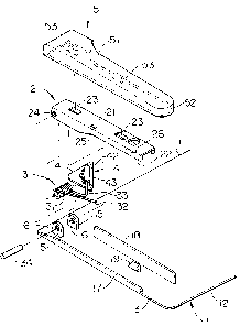
First, a first embodiment shown in Fig. 1 to Fig. 7 is
explained. The paper binder comprises a rectangular mount 1 which
is made from synthetic resin and on the top of which paper to be
bound is mounted, a lever member 2 which is made from a metal plate
and one end of which is rotatably supported by the mount 1, a metal
spring member 3 which is designed to elastically urge upward the
free end of the lever member 2, a pressing means 4 of metal which
is attached to one end of the metal spring member 3 and which grips
the corner of the paper between the same pressing means 4 and the
mount 1 when the free end of the lever member 2 is pressed
downward, and a cover member 5 of synthetic resin which is fitted
so as to cover the lever member 2.
As seen in Figs. 1 and 2, the mount 1 forms a rectangle
consisting of four sides of an upper end 11, a lower end 12, a left
end 13, and a right end (not illustrated). A support of the lever
member 2 is provided at the left end 13 side. and its right side
constitutes a flat portion for the placement of paper such as
9
215993
slips, memos ore the like. At the corner formed by the upper end
11 and the left end 13 of the mount 1, a pair of bearing
projections 15 are provided integrally with the mount 1 at an
interval in the left-to-right direction. Shaft holes 16 are
pierced in these bearing projections 15 respectively. A pair of
guide projections 17 and 18 are provided on the mount 1 integrally
therewith so as to extend in the direction from the upper end 11
toward the lower end 12. The distance between these guide
projections 17 and 18 must be at least longer than the maximum
width of the cover member 5, and it is preferable that the height
of guide projection 18 be set so as to be higher than the maximum
thickness of the paper to be bound. On the other hand, the height
of guide projection 17 is lower than guide projection 18, but it
may also be equal to that of the guide portion 18. An engagement
portion 19 of a below-mentioned lock means is provided integrally
with the mount 1 between the guide projections 17 and 18. A
portion of the mount 1 on the right side of the guide projection 18
constitutes a placement site for paper.
The lever member 2 includes a rectangular top portion 21 and
side portions 22 which are respectively bent downward from the two
lengthwise ends of the top portion 21. The length of the top
portion 21 is shorter than the length between the upper end 11 and
the lower end 12 of the mount 1. A pair of nib receivers 23 are
formed at an interval in the lengthwise direction on the top
215993
portion 21. At one end of the two sides portions 22, shaft holes
24 which align with the shaft holes 16 are respectively provided.
Between the pair of nib receivers 23 on the top portion 21, an
engagement projection 25 is provided so as to project downward and
is designed to fix one end of the metal spring member 3 to the
lever member 2. At the end opposite to the shaft holes 24 side of
the top portion 21, that is, at the free end side, an engagement
projection 26 is formed which serves as an engagement means for
engaging with the engagement portion 19 of the mount 1, and which
is removed from the engagement portion 19 by a slight sideways
shifting of the free end of the lever member 2.
The metal spring member 3 includes a central coil portion 31,
an engagement end 32 of linear shape which is one end portion of
the coil portion 31 and which engages with the engagement
projection 25 of the lever member 2, and a retention end portion 33
which is the other end of the coil portion 31 and which rotatably
retains the pressing means 4. The engagement end portion 32 and
the retention end portion are elastically urged by the coil portion
31 in the directions opposite to each other. The axial length of
the coil portion 31 is slightly shorter than the width or distance
between the two side portions 22 of the lever member '2. The
retention end portion 33 is bent outward from its middle at an
angle of approximate 45° . With regard to the metal spring member
3, after the coil portion 31 is positioned between the bearing
11
2155993
projections 15 so that its openings align with the shaft holes 16
of the bearing projections 15, it is secured to the mount 1 by
passing a shaft 34 which has an axial length approximately equal to
the distance between the bearing projections 15 through the
openings of the coil portion 31 from one of the shaft holes 16.
As shown in detail in the drawings from Fig. 3 to Fig. 7, the
pressing means 4 made from metal plate includes a pressing plate
member 41 which has the shape of an approximate right triangle, and
a fixed plate member 42 which is fixed to the top of the pressing
plate member 41 and which rotatably supports the retention end
portion 33 of the metal spring member 3 together with the pressing
plate member 41. The pressing plate member 41 and the fixed plate
member 42 are both made from metallic plate material. With regard
to the pressing plate member 41, an insertion groove 43 is formed
in the surface of the pressing plate member 41 by bending back a
portion of the side which faces opposite to its right angled
summit, and a pair of claws 44 are formed by cut-out on the right
angled summit side which lies opposite to the insertion groove 43.
Between the pair of claws 44, a positioning protrusion 45 which
projects upward is formed by embossing or the like. On the fixed
plate member 42, there are formed a flat first skirt portion 46
which inserts into the insertion groove 43, a second skirt portion
47 which is also flat and which is attached to the surface of the
pressing plate member 41 by the claws 44, and an insertion portion
12
21 X5993
48 of approximately semi-cylindrical shape which is positioned
between these first and second skirt portions 46 and 47, and which
is designed to allow passage of the retention end portion 33 of the
metal spring member 3. The height of the insertion portion 48 is
set to be higher than the diameter of the retention end portion 33
of the metal spring member 3, and a constricted portion 49 which
falls downward is formed at the center of its axial length. With
regard to the constricted portion 49, as shown in Fig. 3, if the
fixed plate member 42 is fixed to the pressing plate member 41 in
the state in which a step portion 34a formed in the retention end
portion 33 of the metal spring member 3 is positioned at the
constricted portion 49, the retention end portion 33 can be
rotatably retained without any dislodgement of the retention end
portion 33 from the insertion portion 48. A positioning hole 50 is
pierced in the second skirt portion 47 into which the positioning
protrusion 45 is inserted f.or purposes of determining the position
of the fixed plate member 42.
The cover member 5 is made of synthetic resin, and is provided
with an upper plate 51 and a circumferential face 52 which is
formed integrally with the upper plate 51 so as to extend downward
from the periphery of the upper plate 51 so that the cover member 5
covers the lever member 2 and the bearing projections 15 from
above. On the underside of the upper plate 51, nibs 53 are
provided so as to project downward to be inserted into the nib
13
CA 02155993 2001-04-03
receivers 23 for purposes of fixing the cover member 5 to the lever
member 2.
Next, the assembly of the paper binder will be explained.
First, the pressing means 4 is secured to the retention end portion
33 of the metal spring member 3. This is done by raising in
advance the pair of claws 44 provided on the pressing plate member
41 of the pressing means 4 as shown in Figs. 3 and 7, and, first,
inserting the first skirt portion 46 of the fixed plate member 42
into the insertion groove 43 of the pressing plate member 41.
Next, the retention end portion 33 of the metal spring member 3 is
passed through the insertion portion 48 of the fixed plate member
42, the positioning protrusion 45 is inserted into the positioning
hole 50 in the state where ,the step portion 34a is positioned in
the constricted portion 49, and the position of the fixed plate
member 42 relative to the pressing plate member 41 is fixed, after
which the pair of claws 44 are bent back and the second skirt
portion 47 side of the fixed plate member 42 is fixed in place.
After the pressing means 4 has been secured in the metal spring
member 3 in this way, the coil portion 31 of the metal spring
member 3 and the end of the lever member 2 at the shaft hole 24
side are positioned between the bearing projections 15, and after
the openings of the coil portion 31 and the shaft holes 16 of the
bearing projections 15 are positioned in alignment, the shaft 34 is
made to pass through from one of the shaft holes 16 of the bearing
14
215993
projections 15. By this means, the lever member 2 and the metal
spring member 3 are secured to the mount 1. Next, the engagement
end 32 of the metal spring member 3 is engaged in the engagement
projection 25 of the lever member 2. Finally, the cover member 5
is fit on so that it covers the lever member 2 and the bearing
projections 15 from above. By this means, the nibs 53 of the cover
member 5 are inserted into the nib receivers 23 of the lever member
2, and the two are firmly fixed together. In this way, assembly
can be effected by a simple process.
In the case where paper 6 such as slips are bound in this
paper binder (see Fig. 2), the free end of the lever member 2 is
shifted slightly to the side while pushing it, so that the
engagement projection 26 is removed from the engagement portion 19
of the mount 1. By this means, the free end side of the lever
member 2 is raised by the metal spring member 3, and the pressing
means 4 also separates from the mount 1. Here, the left end of the
paper 6 is matched to the guide projection 18, and is positioned so
that the pressing plate member 41 presses down on the corner of the
paper 6 when the pressing means 4 is lowered. The free end of the
2p lever member 2 is then lowered, the engagement projection 26 of the
lever member 2 engages with the engagement portion 19 of the mount
1, and the free end of the lever member 2 is secured in the lowered
state. As a result, since the pressing means 4 is elastically
pressed down on the mount 1, the corner of the paper 6 is firmly
2I5~993
gripped between the pressing means 4 and mount 1. Since it is the
normally blank corner portion of the paper 6 which is pressed, the
pressing means 4 does not cover any of the contents recorded on the
paper 6. Since the pressing plate member 41 of the pressing means
4 contacts the narrow portion at the corner of the paper 6, even if
the paper 6 is bent back from this portion, the bounce of the paper
6 generated by this bending is weak, and even if a large number of
pages of the paper 6 are opened by bending them from their corner,
the overall bounce does not become large. Consequently, even if a
large number of pages of the paper 6 are gripped and leafed
through, the paper can be securely gripped without any dislodgement
from between the pressing plate member 41 and the mount 1.
Next, a second embodiment shown in the drawings from Fig. 8 to
Fig. 11 will be explained. In this second embodiment, the pressing
means 4 is made from synthetic resin, and the pair of guide
projections 17 and 18 are made to serve also as the bearing
projections which were separately provided in the first embodiment.
That is, the pressing means 4 is composed from a pressing plate
member 61 shaped like an approximate right triangle. As shown in
detail in Fig. 10, a groove projection 62 having a groove in which
the retention end portion 33 of the metal spring member 3 can be
rotatably press fitted, and a stopper projection 63 for regulating
the movement of the end of the retention end portion 33 are formed
on the top of the pressing plate member 61. A stopper 64 is formed
16
215993
at the tip of the retention end portion 33. The stopper 64 is a
flat piece with a width that is longer than the groove width of the
groove projection 62. By means of the stopper 64, the retention
end portion 33 is prevented from falling out of the groove
projection 62 in the direction which lies opposite to the stopper
projection 63. With regard to the stopper 64, as shown in Fig. 11,
when the free end of the lever member 2 is raised and the pressing
plate member 61 is freed, the stopper 64 contacts an inclined faces
65 and 66 of the pressing plate member 61, and prevents any
inclination beyond what is required. By this means, as shown in
Fig. 9, even if the free end of the lever member 2 is raised, the
side positioned at the upper end side of the pressing plate member
61 is lowered, and there is no impediment to the insertion of the
paper from the direction of the lower end 12 of the mount 1.
Furthermore, in this second embodiment, there is only the
lever member 2 without the cover member 5. The lever member 2
includes a top portion 67, and a side face portion 68 which is bent
downward from one side of the top portion 67 and which faces
opposite the guide projection 17. The engagement portion 19 is
provided on the inner face of the guide projection 17, and as a
result of the engagement of the engagement portion 19 in an
engagement hole 69 which is pierced in the side face portion 68 of
the lever member 2, the free end of the lever member 2 is secured
in the lowered state. When releasing the engagement, as shown in
17
~1~599~
Fig. 8 and Fig. 9, the engagement portion 19 is disengaged from the
engagement hole 69 by slightly shifting the free end of the lever
member 2 toward the right. A convex portion 70 designed to allow
passage of the retention end portion 33 of the metal spring member
3 is formed in the guide projection 18, and the shaft 35 is
supported at the tips of the guide projections 17 and 18. The
portion of the mount 1 positioned on the right side of the guide
projection 18 is shorter than in the first embodiment, and a guide
projection 71 is formed integrally therewith at the upper end of
the mount 1 so as to project upward and guide the top side of the
paper. The reference numeral number 72 in the mount 1 designates
screw holes.
As shown in Fig. 12, the paper binder of this second
embodiment is attached to a file holder 76 consisting~of a front
cover 73, a rear cover 74, and a back cover 75. That is, the paper
binder is fixed by screws (not illustrated) to the back cover 75
from the screw holes 72 of the mount 1 so that the guide projection
17 of the mount 1 is positioned at the left shoulder of the rear
cover 74 along the borderline with the back cover 75, or it is
fixed by the adhesion of the rear face of the mount 1 to the back
cover 75. By this means, as mentioned above, since one can grip
the blank corner portion, not of comparatively small paper such as
slips, but of paper 80 such as documents, literature, or the like,
of B5 and A4 size and above, it is possible to offer a binder where
18
~1~5993
leafing is made easy and where the leafed pages do not fall back
when one releases one's hand from them.
In the aforementioned first and second embodiments, the mount
1 is made from synthetic resin, but in a third embodiment shown in
Fig. 13, the mount 1 is made from metal plate material, the lever
member 2 is made longer, and the lever member 2 can be lowered by a
light force. That is, in Fig. 13, the guide projection 17 is
formed by bending back the left side edge of the mount 1, and a
guide projection 71 is formed by bending back the top side edge of
the mount 1. As members corresponding to the guide projection 18
which grips the lever member 2 of the mount 1 and which is
positioned on the opposite side, three guide projections 81 are cut
out from the mount 1 at predetermined intervals, and take shape by
being raised up. With regard to the shaft 35 which supports the
lever member 2 and the metal spring member 3, one end is supported
by the guide projection 17, and the other end is supported by a
bearing projection 82 which is cut out of the mount 1 and raised up
in the same manner as the guide projections 81. What enables the
lever member 2 to be lowered by a light force is that the metal
spring member 3 of strong elasticity can be used, which imparts a
correspondingly strong pressing force to the pressing means 4.
Consequently, a binder can be offered which is able to bind a
larger number of pages than in the case of either the first or
second embodiment, and one can also bind large paper of B4 or A3
19
CA 02155993 2001-04-03
size by attaching the paper binder to a file holder.
In the case where the paper binder is attached to a file
holder made from flexible material, it is necessary to make the
length of the lever member 2 shorter than the length of the mount 1
which is positioned underneath it. This is because, if the lever
member 2 is longer than the mount 1, when force is imparted to the
free end of the lever member 2 and it is lowered, the shaft 34 side
is raised, and it is possible that the binder might break from the
lower end portion 12 of the mount 1.
In each of the aforementioned embodiments, a lever member 2 is
provided at the left end of the mount 1, and the pressing means 4
is positioned at the right side of the lever member 2, but in the
case of righthand binding of the paper, the lever member 2 may be
provided at the right end of the mount l, the pressing means 4
being positioned at, the left side of the lever member 2.
In the foregoing, the present invention has been explained
with reference to preferable embodiments, and these descriptions
have been made in order to facilitate understanding, but the
present invention is capable of many variations or modifications so
long as no departure is made from the scope of the accompanying
claims.